Page 2118 of 2893
����
�µ
�µ �µ
�µ
Special Tools Required
YES
NO YES
NO
22-170Exterior Lights
HID Lamp System Troubleshooting
A
B
A transient high tension (25,000")
���
�(�#�'�����!���������
�����
�����������������)����
�µ
�µ �µ
�µ
Special Tools Required
YES
NO YES
NO
22-170Exterior Lights
HID Lamp System Troubleshooting
A
B
A transient high tension (25,000 V) occurs at the
bulb sockets or the high intensity discharge (HID)
lamps when the combination light switch is turned
ON, it may cause serious electrical shock or
electrocution if you do not observe the cautions.
Never turn on the combination light switch before fitting the HID bulbs to their bulb sockets
and completing the reassembly of the headlight
assembly.
Do not service the headlights assembly in wet conditions, such as rain or snow, near a sprinkler
system, or when your hands are wet to prevent
electrocution.
Do not touch the surface of the HID bulbs with your bare hands and do not stain it with any oils
and fats.
Do not disassemble the inverter unit and the igniter unit.
Do not turn on the HID bulb by using a power source other than the battery mounted on your
vehicle.
HID bulb test light 07AAJ-S3MA100
NOTE: Before troubleshooting the HID Lamp System,
do the multiplex integrated control system
troubleshooting using B-CAN System Diagnosis Test
Mode A (see page 22-93). 1. Check the No. 16 (15 A), No. 17 (15 A), and No. 21 (30 A) fuses in the under-dash fuse/relay box.
Go to step 2.
Replace the fuse(s), and recheck.
2. Turn the combination light switch OFF.
3. Do the battery terminal disconnection procedure (see page 22-68). 4. Remove the socket from the HID bulb (see page
22-168).
5. Check for corrosion (A) and traces of electrical arcing (B) at the socket mating part.
Go to step 7.
Replace the socket, and recheck.
Ar e f uses OK ? I s t he sock et cor r od ed or bur nt ?
08/08/21 14:27:00 61SNR030_220_0172
ProCarManuals.com
DYNOMITE -2009-
Page 2120 of 2893

HID UNIT 2P CONNECTOR
LEFT HEADLIGHT (PUR)
RIGHT HEADLIGHT (")
��������
����
�µ
�µ
�µ
�µ
YES
NO
LEFT HEADLIGHT
RIGHT HEADLIGHT
YES
NO
22-172Exterior Lights
HID Lamp System Troubleshooting (cont’d)
HID UNIT 2P CONNECTOR
LEFT HEADLIGHT (PUR)
RIGHT HEADLIGHT (GRN)
HID UNIT 2P CONNECTOR (LEFT HEADLIGHT)PUR
UNDER-DASH FUSE/RELAY BOX CONNECTOR G (21P)
UNDER-DASH FUSE/RELAY BOX CONNECTOR F (34P) HID UNIT 2P CONNECTOR (RIGHT HEADLIGHT) GRN
16. Measure the voltage between the HID unit 2P
connector terminal No. 2 and body ground.
Substitute a known-good HID unit, and
recheck. If the symptom/indication goes away,
replace the original HID unit.
Go to step 17.
17. Disconnect under-dash fuse/relay box connector G (21P) and/or F (34P) .1: Left headlight
2: Right headlight 18. Check for continuity between under-dash fuse/relay
box G (21P) terminal No. 17 or F (34P) terminal
No. 4 and HID unit 2P connector terminal No. 2.
Replace the under-dash fuse/relay box.
Repair an open in the wire between the
under-hood fuse/relay box and the HID unit.
12
Wire side of female terminals
Wire side of female terminalsWire side of female terminals
Wire side of female terminals Wire side of female terminals
Is there battery voltage?
Is there continuity?
08/08/21 14:27:00 61SNR030_220_0174
ProCarManuals.com
DYNOMITE -2009-
Page 2121 of 2893
���
����
����
�(�#�'���������������
�����
���
�
���
�"�����)����
22-173
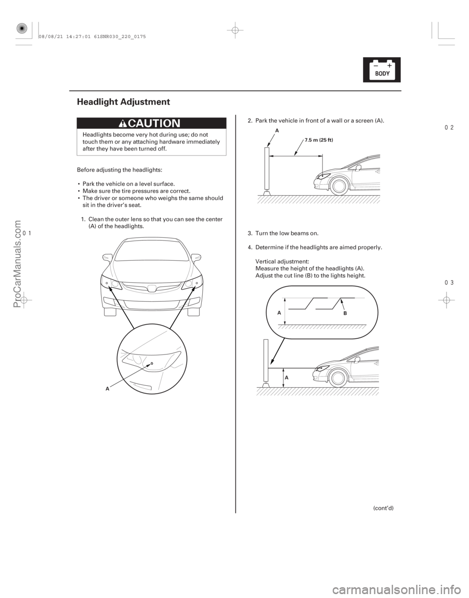
Headlight Adjustment
A A
7.5 m (25 ft)
A A B
Headlights become very hot during use; do not
touch them or any attaching hardware immediately
after they have been turned off.
Before adjusting the headlights: Park the vehicle on a level surface.
Make sure the tire pressures are correct.
The driver or someone who weighs the same should sit in the driver’s seat.
1. Clean the outer lens so that you can see the center (A) of the headlights. 2. Park the vehicle in front of a wall or a screen (A).
3. Turn the low beams on.
4. Determine if the headlights are aimed properly.
Vertical adjustment:
Measure the height of the headlights (A).
Adjust the cut line (B) to the lights height.
(cont’d)
08/08/21 14:27:01 61SNR030_220_0175
ProCarManuals.com
DYNOMITE -2009-
Page 2122 of 2893
����
22-17422-174 Exterior Lights
Headlight Adjustment (cont’d) Headlight Replacement
U: UP
D: DOWN
A A
D B
C
A
5. If necessary, open")
����
����
���
�(�#�'���������������
�����
���
�
���
� �����)����
22-17422-174 Exterior Lights
Headlight Adjustment (cont’d) Headlight Replacement
U: UP
D: DOWN
A A
D B
C
A
5. If necessary, open the hood and adjust the
headlights to local requirements by turning the
adjusters (A). A transient high tension (25,000 V) occurs at the bulb sockets or the high intensity discharge (HID)
lamps when the combination light switch is turned
ON, it may cause serious electrical shock or
electrocution if you do not observe the cautions.
Do not service the headlights assembly in wet
conditions, such as rain or snow, near a sprinkler
system, or when your hands are wet to prevent
electrocution.
1. Remove the front bumper (see page 20-146).
2. Remove the connectors (A) from the headlight assembly (B).
3. Remove the five bolts, then remove the headlight.
4. Remove the bolt (C) and the corner upper beam (D) from the headlight.
5. Install the headlight in the reverse order of removal.
6. After replacement, adjust the headlight to local requirements.
The illustration is shown from
back side of left headlight.
08/08/21 14:27:01 61SNR030_220_0176
ProCarManuals.com
DYNOMITE -2009-
Page 2123 of 2893
����
22-17422-174 Exterior Lights
Headlight Adjustment (cont’d) Headlight Replacement
U: UP
D: DOWN
A A
D B
C
A
5. If necessary, open")
����
����
���
�(�#�'���������������
�����
���
�
���
� �����)����
22-17422-174 Exterior Lights
Headlight Adjustment (cont’d) Headlight Replacement
U: UP
D: DOWN
A A
D B
C
A
5. If necessary, open the hood and adjust the
headlights to local requirements by turning the
adjusters (A). A transient high tension (25,000 V) occurs at the bulb sockets or the high intensity discharge (HID)
lamps when the combination light switch is turned
ON, it may cause serious electrical shock or
electrocution if you do not observe the cautions.
Do not service the headlights assembly in wet
conditions, such as rain or snow, near a sprinkler
system, or when your hands are wet to prevent
electrocution.
1. Remove the front bumper (see page 20-146).
2. Remove the connectors (A) from the headlight assembly (B).
3. Remove the five bolts, then remove the headlight.
4. Remove the bolt (C) and the corner upper beam (D) from the headlight.
5. Install the headlight in the reverse order of removal.
6. After replacement, adjust the headlight to local requirements.
The illustration is shown from
back side of left headlight.
08/08/21 14:27:01 61SNR030_220_0176
ProCarManuals.com
DYNOMITE -2009-
Page 2124 of 2893
���� ����
�����
�(�#����������������
�����
�����
���
� �����)����
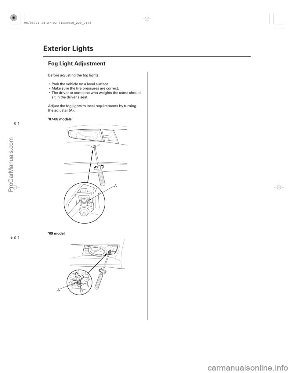
’07-08 models ’09 model
FOG LIGHT: 55 W FOG LIGHT: 55 W
22-17522-175")
���
�����(�#�'�������%�������
�����
�����
���
� �����)���� ����
�����
�(�#�'���������������
�����
�����
���
� �����)����
’07-08 models ’09 model
FOG LIGHT: 55 W FOG LIGHT: 55 W
22-17522-175
Fog Light Replacement
AB
A A
B
A
1. Remove the fog light cover.
2. Remove the mounting screw from the fog light.
3. Remove the fog light (A) from the front bumper.
4. Disconnect the 2P connector (B) from the fog light.
5. Turn the bulb socket (A) 60 ° counterclockwise to remove it from the housing.
6. Install the fog light in the reverse order of removal.
7. After replacement, adjust the fog lights to local requirements (see page 22-176). 1. Remove the mounting screw from the fog light.
2. Remove the fog light (A) from the front bumper.
3. Disconnect the 2P connector (B) from the fog light.
4. Turn the bulb socket (A) 60 ° counterclockwise to
remove it from the housing.
5. Install the fog light in the reverse order of removal.
6. After replacement, adjust the fog lights to local requirements (see page 22-176).
08/08/21 14:27:02 61SNR030_220_0177
ProCarManuals.com
DYNOMITE -2009-
Page 2125 of 2893
���
����
�(�#�'���������������
�����
�����
���
�"�����)���� ’07-08 models
’09 model
22-176Exterior Lights
Fog Light Adjustment
A
A
Before adjusting the fog lights: Park the vehicle on a level surface.
Make sure the tire pressures are correct.
The driver or someone who weights the same should sit in the driver’s seat.
Adjust the fog lights to local requirements by turning
the adjuster (A).
08/08/21 14:27:02 61SNR030_220_0178
ProCarManuals.com
DYNOMITE -2009-
Page 2127 of 2893
��������
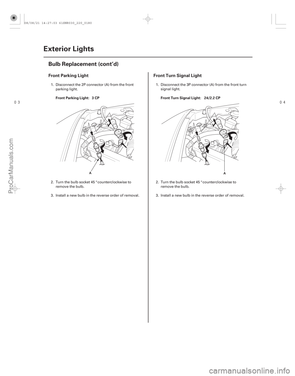
Front Parking LightFront Turn Signal Light
Front Parking Light: 3 CP Front Turn Signal Light: 24/2.2 CP
22-178Exterior Lights
Bulb Replacement (cont’d)
A
A
1. Disconnect the 2P connector (A) from the front
parking light.
2. Turn the bulb socket 45 ° counterclockwise to remove the bulb.
3. Install a new bulb in the reverse order of removal. 1. Disconnect the 3P connector (A) from the front turn
signal light.
2. Turn the bulb socket 45 ° counterclockwise to remove the bulb.
3. Install a new bulb in the reverse order of removal.
08/08/21 14:27:03 61SNR030_220_0180
ProCarManuals.com
DYNOMITE -2009-