Page 790 of 2893
�
��
��������
����
13-19
A
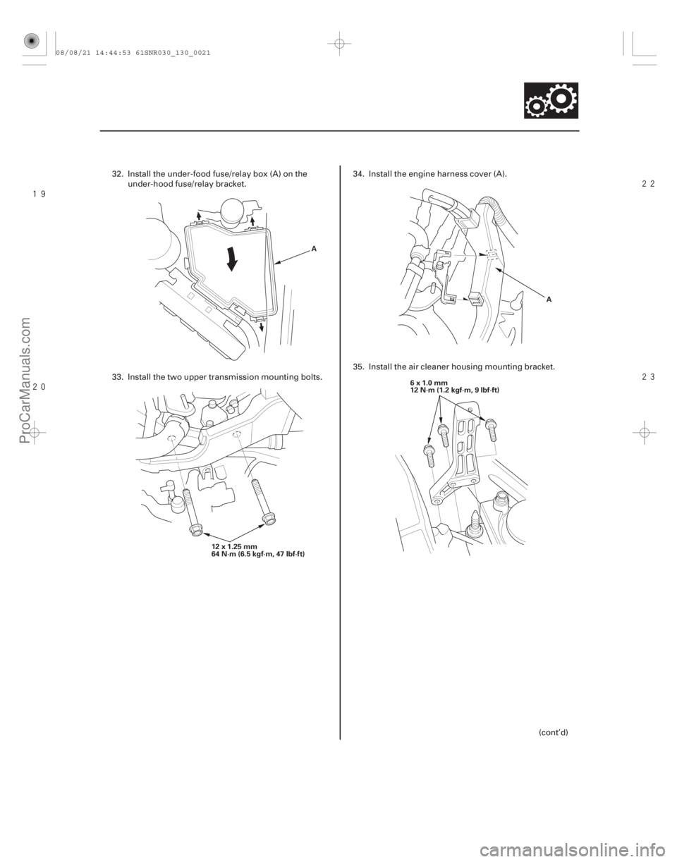
12 x 1.25 mm
64N·m(6.5kgf·m,47lbf·ft) A
6x1.0mm
12 N·m (1.2 kgf·m, 9 lbf·ft)
32. Install the under-food fuse/relay box (A) on the under-hood fuse/relay bracket.
33. Install the two upper transmission mounting bolts. 34. Install the engine harness cover (A).
35. Install the air cleaner housing mounting bracket.
(cont’d)
08/08/21 14:44:53 61SNR030_130_0021
ProCarManuals.com
DYNOMITE -2009-
Page 792 of 2893

6x1.0mm
9.8 N·m
(1.0 kgf·m,
7.2 lbf·ft)
(P/N 08798-9002) C
D B
C A
6x1.0mm
9.8 N·m
(1.0 kgf·m, 7.2 lbf·ft)
6x1.0mm
9.8 N·")
����
��������
13-21
A
B C
B
A 8x1.25mm
22 N·m (2.2 kgf·m, 16 lbf·ft)
6x1.0mm
9.8 N·m
(1.0 kgf·m,
7.2 lbf·ft)
(P/N 08798-9002) C
D B
C A
6x1.0mm
9.8 N·m
(1.0 kgf·m, 7.2 lbf·ft)
6x1.0mm
9.8 N·m
(1.0 kgf·m, 7.2 lbf·ft)
6x1.0mm
9.8 N·m
(1.0 kgf·m, 7.2 lbf·ft)
39. Connect the back-up light switch connector (A) and the output shaft (countershaft) speed sensor
connector (B). Install the harness clips (C).
40. Apply super high temp urea grease (P/N 08798-9002) to the end of the slave cylinder
pushrod. Install the slave cylinder (A), then install
the clutch line bracket (B). Be careful not to bend
the clutch line. 41. Install the battery base (A) with the coolant
reservoir (B).
42. Install the harness clips (C) and the intake air duct (D).
43. Install the air cleaner assembly (see page 11-345).
44. Do the battery installation procedure (see page 22-69).
45. Install the under-cowl panel and the cowl cover (see page 20-163).
46. Check the shift lever and the clutch operation.
47. Check the wheel alignment (see page 18-5).
48. Test-drive the vehicle.
08/08/21 14:44:55 61SNR030_130_0023
ProCarManuals.com
DYNOMITE -2009-
Page 846 of 2893
���
����
�(�#����������������
���
�
���������
�\"�����)����
13-7713-77
Reverse Lockout Solenoid Test Reverse Lockout Solenoid Disassembly/Reassemb")
���
�(�#�'���������������
���
�
���������
�������)���
����
�(�#�'���������������
���
�
���������
�"�����)����
13-7713-77
Reverse Lockout Solenoid Test Reverse Lockout Solenoid Disassembly/Reassembly
REVERSE LOCKOUT SOLENOID
2P CONNECTOR
A
1. Remove the reverse lockout solenoid (see page13-77).
2. Connect battery positive terminal to the r everse
lockout solenoid 2P connector No. 2 terminal, and
connect the battery negative terminal to the No. 1
terminal.
3. Make sure the reverse lockout solenoid works. If the reverse lockout solenoid does not work, replace
it. 1. Do the battery removal procedure (see page 22-69).
2. Remove the air cleaner assembly (see page 11-345).
3. Remove the battery base (see step 4 on page 13-84).
4. Disconnect the output shaft (countershaft) speed
sensor connector, the back-up light switch
connector, and the r everse lockout solenoid
connector (see step 6 on page 13-84).
5. Carefully remove the shift cables and the cable bracket together to avoid bending the cables (see
step 7 on page 13-85).
6. Remove the reverse lockout solenoid (A).
(cont’d)
Terminal side of male terminals
08/08/21 14:46:40 61SNR030_130_0079
ProCarManuals.com
DYNOMITE -2009-
Page 847 of 2893

C
B
A
6x1.0mm
12 N·m
(1.2 kgf·m,
8.7 lbf·ft)
A
7. Remove the roller (A), the select lock return sp")
���������
13-78Reverse Lockout System
Reverse Lockout Solenoid Disassembly/Reassembly (cont’d)
C
B
A
6x1.0mm
12 N·m
(1.2 kgf·m,
8.7 lbf·ft)
A
7. Remove the roller (A), the select lock return spring
(C), and select lock cam B.
8. Install the components of the r everse lockout
solenoid in the reverse order of removal.
9. Clean any dirt and oil from the mating surface of the reverse lockout solenoid and the change lever
assembly.
10. Apply liquid gasket, P/N 08718-0001 evenly to the change lever assembly mating surface of the
reverse lockout solenoid. Install the com ponent
within 5 minutes of applying the liquid gasket.
NOTE: If you apply liquid gasket P/N 08718-0012, the component must be installed within 4 minutes.
If too much time has passed after applying the liquid gasket, remove the old liquid gasket and
residue, then reapply new liquid gasket. 11. Install the reverse lockout solenoid (A).
12. Install the cable bracket and the shift cables (see
step 37 on page 13-97).
13. Connect the r everse lockout solenoid connector,
the back-up light switch connector, and the output
shaft (countershaft) speed sensor connector (see
step 39 on page 13-97).
14. Install the battery base (see step 41 on page 13-98).
15. Install the air cleaner assembly (see page 11-345).
16. Do the battery installation procedure (see page 22-69).
08/08/21 14:46:40 61SNR030_130_0080
ProCarManuals.com
DYNOMITE -2009-
Page 853 of 2893
����
Special Tools Required
13-84
Manual Transmission
Transmission Removal
A
B C
D
A A
B
D
C
A
B
Engine hanger adapter VSB02C0000")
�Ì
�Ï
���
����
����
�(�#�'���������������
�����
����������� �����)����
Special Tools Required
13-84
Manual Transmission
Transmission Removal
A
B C
D
A A
B
D
C
A
B
Engine hanger adapter VSB02C000015
2006 Civic engine hanger VSB02C000025
Engine support hanger, A and Reds AAR-T 1256
Front subframe adapter VSB02C000016
These special tools are available through the Acura
Canada Technical Tools Department; FAX
866-398-8665/e-mail: ch_technicaltools ch.honda.com
NOTE: Use fender covers to avoid damaging painted
surfaces.
1. Do the battery removal procedure (see page 22-69).
2. Remove the cowl cover and the under-cowl panel (see page 20-163).
3. Remove the air cleaner assembly (see page 11-345).
4. Remove the harness clips (A) and the intake air duct (B), then remove the battery base (C) with the
coolant reservoir (D). 5. Remove the clutch line bracket (A), then carefully
move the slave cylinder (B) out of the way to avoid
bending the clutch line.
NOTE: Do not press the clutch pedal after the slave
cylinder has been moved.
6. Disconnect the back-up light switch connector (A), the output shaft (countershaft) speed sensor
connector (B), the r everse lockout solenoid
connector (C), and the harness clips (D).
08/08/21 14:47:19 61SNR030_130_0086
ProCarManuals.com
DYNOMITE -2009-
Page 854 of 2893
���
��������
����
’06 model
’07-09 models
13-85
A
D
C
D
A
D
B C
D A
B
C A
A
7. Remove the cotter pins (A) or the lock pins (B), and the shift cable bracket (C), then disconnect the shift
cables (D) from the top of the change lever
assembly. Carefully remove both cables and the
bracket together to avoid bending the cables. 8. Remove the harness clips (A) from the clutch cable
bracket (B) and the harness bracket (C).
9. Remove the air cleaner housing bracket (A).
(cont’d)
08/08/21 14:47:20 61SNR030_130_0087
ProCarManuals.com
DYNOMITE -2009-
Page 865 of 2893
���
��������
����
13-96Manual Transmission
Transmission Installation (cont’d)
12x1.25mm
64 N·m (6.5 kgf·m, 47 lbf·ft)
A6x1.0mm
12 N·m
(1.2 kgf·m, 9 lbf·ft)
6x1.0mm
12 N·m
(1.2 kgf·m,
9lbf·ft)
A B
C A
33. Install the two upper transmission mounting bolts.
34. Install the engine harness cover (A). 35. Install the air cleaner housing mounting bracket.
36. Install the harness clips (A) on the shift cable
bracket (B) and the harness bracket (C).
08/08/21 14:47:29 61SNR030_130_0098
ProCarManuals.com
DYNOMITE -2009-
Page 867 of 2893

6x1.0mm
9.8 N·m
(1.0 kgf·m,
7.2 lbf·ft)
8x1.25mm
22 N·m (2.2 kgf·m, 16 lbf·ft)
(P/N 08798-9002) B
A
6x1.0mm
9.8 N·m
(1.0")
����
����
13-98Manual Transmission
Transmission Installation (cont’d)
6x1.0mm
9.8 N·m
(1.0 kgf·m,
7.2 lbf·ft)
8x1.25mm
22 N·m (2.2 kgf·m, 16 lbf·ft)
(P/N 08798-9002) B
A
6x1.0mm
9.8 N·m
(1.0 kgf·m, 7.2 lbf·ft) 6x1.0mm
9.8 N·m (1.0 kgf·m, 7.2 lbf·ft)
6x1.0mm
9.8 N·m (1.0 kgf·m, 7.2 lbf·ft) B
A
C
C
D
40. Apply super high temp urea grease (P/N 08798-
9002) to the end of the slave cylinder pushrod.
Install the slave cylinder (A), then install the clutch
line bracket (B). Be careful not to bend the clutch
line.
41. Install the battery base (A) with the coolant reservoir (B). 42. Install the harness clips (C) and the intake air duct
(D).
43. Install the air cleaner assembly (see page 11-345).
44. Do the battery installation procedure (see page 22-69).
45. Install the under-cowl panel and the cowl cover (see page 20-163).
46. Check the shift lever and the clutch operation.
47. Check the wheel alignment (see page 18-5).
48. Test-drive the vehicle.
08/08/21 14:47:31 61SNR030_130_0100
ProCarManuals.com
DYNOMITE -2009-