Page 1128 of 2893

B
C
12. Connect the A/T oil pressure gauge to the 1st clutch pressure inspe")
�´�µ�µ
�µ
����
����
Pressure Fluid Pressure
Standard Service Limit
14-212Automatic Transmission
Pressure Test (cont’d)
B
C
12. Connect the A/T oil pressure gauge to the 1st clutch pressure inspection port (B).
13. Remove the intake air duct (see page 11-348) and the air cleaner assembly (see page 11-345).
14. Remove the harness cover from its bracket, and connect the A/T oil pressure gauge to the 2nd
clutch pressure inspection port (C). Then
temporarily install the air cleaner assembly and the
intake air duct. 15. Start the engine, and shift to S.
16. Shift to 1st gear by pressing the paddle shifter
(downshift switch) if needed, and measure the 1st
clutch pressure at the 1st clutch pressure
inspection port (B) while holding the engine speed
at 2,000 rpm.
17. Upshift to 2nd gear by pressing the paddle shifter (upshift switch), and measure the 2nd clutch
pressure at the 2nd clutch pressure inspection port
(C) while holding the engine speed at 2,000 rpm.
1st clutch
(B)
2nd clutch
(C) 890 970 kPa
(9.1 9.9 kgf/cm ,
130 140 psi)
840 kPa
(8.6 kgf/cm ,
120 psi)
18. Turn the engine off, remove the air cleaner assembly (see page 11-345) and the intake air duct
(see page 11-348), then disconnect the A/T oil
pressure gauge from the 1st and 2nd clutch
pressure inspection ports.
19. Install the sealing bolts to the 1st and 2nd clutch pressure inspection ports with new sealing
washers, and tighten the bolts to 18 N·m (1.8 kgf·m,
13 lbf·ft). Do not reuse the old sealing washers.
20. Install the air cleaner assembly (see page 11-345) and the intake air duct (see page 11-348).
22
08/08/21 14:46:43 61SNR030_140_0214
ProCarManuals.com
DYNOMITE -2009-
Page 1129 of 2893
 and the 5th
clutch pressure i")
�´
�µ �µ
�µ
���
����
Pressure Fluid Pressure
Standard
Service Limit
14-213
D
E
F
21. Connect the A/T oil pressure gauge to the 3rdclutch pressure inspection port (D) and the 5th
clutch pressure inspection port (E).
22. Connect the A/T oil pressure gauge to the 4th clutch pressure inspection port (F). 23. Start the engine, and shift to S.
24. Upshift to 3rd gear by pressing the paddle shifter
(upshift switch), and measure the 3rd clutch
pressure at the 3rd clutch pressure inspection port
(D) while holding the engine speed at 2,000 rpm.
25. Upshift to 4th gear, and measure the 4th clutch pressure at the 4th clutch pressure inspection port
(F) while holding the engine speed at 2,000 rpm.
26. Upshift to 5th gear, and measure the 5th clutch pressure at the 5th clutch pressure inspection port
(E) while holding the engine speed at 2,000 rpm.
890 970 kPa
(9.1 9.9 kgf/cm ,
130 140 psi) 840 kPa
(8.6 kgf/cm ,
120 psi)
(cont’d)
3rdclutch(D)
4thclutch(F)
5thclutch(E)22
08/08/21 14:46:43 61SNR030_140_0215
ProCarManuals.com
DYNOMITE -2009-
Page 1130 of 2893

27. Bring the engine back to an idle, then apply the
brake pedal")
�µ�µ
�µ
Pressure Fluid Pressure
Standard Service Limit Problem Probable causes
14-214Automatic Transmission
Pressure Test (cont’d)
27. Bring the engine back to an idle, then apply the
brake pedal to stop the wheels from rotating.
28. Shift to R, then release the brake pedal. Measure the 4th clutch pressure at the 4th clutch pressure
inspection port (F) while holding the engine speed
at 2,000 rpm.
4th clutch
(F) in R 890 970 kPa
(9.1 9.9 kgf/cm ,
130 140 psi) 840 kPa
(8.6 kgf/cm ,
120 psi)
29. Turn the engine off, then disconnect the A/T oil pressure gauge from the 3rd, 4th, and 5th clutch
pressure inspection ports.
30. Install the sealing bolts in the 3rd, 4th, and 5th clutch pressure inspection ports with new sealing
washers, and tighten the bolts to 18 N·m (1.8 kgf·m,
13 lbf·ft). Do not reuse the old sealing washers. 31. If the pressures are out of the service limit, the
problems and probable causes are listed in the
table.
No or low line
pressure
Torque converter
ATF pump
Regulator valve
Torque converter
check valve
Clogged ATF strainer
No or low 1st clutch
pressure 1st clutch
O-rings
No or low 2nd clutch
pressure 2nd clutch
O-rings
No or low 3rd clutch
pressure 3rd clutch
O-rings
No or low 4th clutch
pressure 4th clutch
O-rings
No or low 5th clutch
pressure 5th clutch
O-rings
No or low 4th clutch
pressure in R Servo valve
4th clutch
O-rings
32. Install the splash shield.
33. Check the ATF level (see page 14-231).
22
08/08/21 14:46:43 61SNR030_140_0216
ProCarManuals.com
DYNOMITE -2009-
Page 1147 of 2893
����
14-231
ATF Level Check
A
A
B
ATF
NOTE: Keep all foreign particles out of the transmission. 1. Park the vehicle on the level ground")
�µ
���
���
����
�(�#�'�������
���
�����������
�������
�"�����)����
14-231
ATF Level Check
A
A
B
ATF
NOTE: Keep all foreign particles out of the transmission. 1. Park the vehicle on the level ground.
2. Warm up the engine to normal operating temperature (the radiator fan comes on), and turn
the engine off. Do not allow the engine to warm up
more than two cycles of the cooling fan.
NOTE: Check the ATF level within 60 90 seconds
after turning the engine off. Higher ATF level may
be indicated if the radiator fan comes on twice or
more.
3. Remove the ATF dipstick (yellow loop) (A), and wipe it with a clean cloth.
4. Insert the dipstick into the transmission.
5. Remove the dipstick and check the ATF level. It should be between the upper mark (A) and the
lower mark (B). 6. If the ATF level is below the lower mark, check for
fluid leaks at the transmission, the hoses, and the
line joints. If a problem is found, fix it before f illing
the transmission with ATF.
NOTE: If the vehicle is driven when the ATF level is
below the lower mark, one or more of these
symptoms may occur: The transmission damage.
The vehicle may not move in any gear.
The vehicle may accelerates poorly, and flares when starting off in D, S, and R.
Vibration when the engine is idling.
7. If the ATF level is above the upper mark, drain the
ATF to proper level (see step 3 on page 14-232).
NOTE: If the vehicle is driven when the ATF level is
above the upper mark, the vehicle may creep
forward while in N, or have problems shifting.
8. If necessary, fill the transmission with ATF through the dipstick hole to bring the fluid level to midway
between the upper mark and the lower mark of the
dipstick. Do not fill the fluid above the upper mark.
Always use genuine Acura ATF-Z1 automatic
transmission fluid (ATF). Using a non-Acura ATF
can affect shift quality.
9. Insert the dipstick back into the transmission with the letters ‘‘ATF’’ pointing toward the front of the
vehicle.
08/08/21 14:46:52 61SNR030_140_0233
ProCarManuals.com
DYNOMITE -2009-
Page 1148 of 2893
����
Automatic Transmission Fluid Capacity:
2.9 L (3.1 US qt) at change
6.5 L (6.9 US qt) at overhaul
14-232 Automatic Transmission
ATF R")
����
���� ����
�(�#�'�������
���
�����������
�������
� �����)����
Automatic Transmission Fluid Capacity:
2.9 L (3.1 US qt) at change
6.5 L (6.9 US qt) at overhaul
14-232 Automatic Transmission
ATF Replacement
A
18 x 1.5 mm
49 N·m
(5.0 kgf·m,
36 lbf·ft)
B
ATF
A
NOTE: Keep all foreign particles out of the transmission. 1. Park the vehicle on the level ground.
2. Warm up the engine to normal operating temperature (the radiator fan comes on), and turn
the engine off.
3. Remove the drain plug (A), and drain the automatic transmission fluid (ATF).
4. Reinstall the drain plug with a new sealing washer (B).
5. Refill the transmission with ATF into the dipstick hole to bring the fluid level between the upper
mark and the lower mark of the dipstick. Always
use Acura ATF-Z1 automatic transmission fluid
(ATF). Using a non-Acura ATF can affect shift
quality.
6. Check that the ATF level is between the upper mark
and the lower mark of the dipstick.
7. Insert the dipstick back into the transmission with the letters ‘‘ATF’’ pointing toward the front of the
vehicle. 8. If the maintenance minder required to replace the
ATF, reset the maintenance minder (see page 3-4),
and this procedure is complete. If the maintenance
minder did not require you to replace the ATF, go
to step 9.
9. Connect the HDS to the DLC (A) located under the driver’s side of the dashboard.
10. Turn the ignition switch to ON (II). Make sure the HDS communicates with the PCM. If it does not, go
to the DLC circuit troubleshooting (see page
11-204).
11. Select BODY ELECTRICAL with the HDS.
12. Select ADJUSTMENT in the GAUGES MENU with the HDS.
13. Select RESET in the MAINTENANCE MINDER MENU with the HDS.
14. Select RESETTING THE ATF with the HDS.
NOTE: If you changed the engine oil at the same
time with the ATF, select RESETTING THE ENGINE
OIL LIFE AND ATF with the HDS instead.
Replace.
08/08/21 14:46:53 61SNR030_140_0234
ProCarManuals.com
DYNOMITE -2009-
Page 1149 of 2893
����
Special Tools Required
14-233
Transmission Removal
A
18x1.5mm
49 N·m
(5.0 kgf·m, 36 lbf·ft)
B
A
B
Engine hanger plate 07AAK-")
�Ì�Ï �Î���
���
�(�#�'�������
���
�����
��������������� �����)����
Special Tools Required
14-233
Transmission Removal
A
18x1.5mm
49 N·m
(5.0 kgf·m, 36 lbf·ft)
B
A
B
Engine hanger plate 07AAK-SNAA120
Engine support hanger, A and Reds AAR-T
1256
2006 Civic engine hanger VSB02C000025
Front subframe adapter VSB02C000016 Available through Acura Canada Technical Tools
Department; Fax 866-398-8665/
e-mail: ch_technicaltools ch.honda.com
NOTE: Use fender covers to avoid damaging painted surfaces.
Special tool engine support hanger must be used with the side engine mount installed.
1. Remove the cowl cover (see page 20-163) and the under-cowl panel.
2. Remove the front grille cover (see page 20-163).
3. Do the battery removal procedure (see page 22-69).
4. Remove the intake air duct (see page 11-348) and the air cleaner assembly (see page 11-345).
5. Remove the battery tray, the battery base, and the resonator.
6. Raise the vehicle on a lift, and make sure it is securely supported and remove the front wheels.
7. Remove the splash shield. 8. Remove the drain plug (A), and drain the automatic
transmission fluid (ATF).
9. Reinstall the drain plug with a new sealing washer (B).
10. Secure the hood in the vertical position.
11. Remove the harness cover (A) from its bracket (B).
(cont’d)
Replace.
08/08/21 14:46:53 61SNR030_140_0235
ProCarManuals.com
DYNOMITE -2009-
Page 1151 of 2893
����
��������
�
��
14-235
A
B
AB
A
B A
B C
07AAK-SNAA120
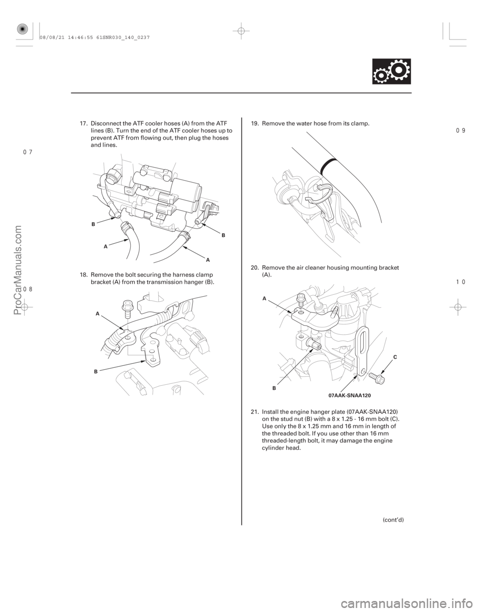
17. Disconnect the ATF cooler hoses (A) from the ATF lines (B). Turn the end of the ATF cooler hoses up to
prevent ATF from flowing out, then plug the hoses
and lines.
18. Remove the bolt securing the harness clamp bracket (A) from the transmission hanger (B). 19. Remove the water hose from its clamp.
20. Remove the air cleaner housing mounting bracket
(A).
21. Install the engine hanger plate (07AAK-SNAA120) onthestudnut(B)witha8x1.25-16mmbolt(C).
Useonlythe8x1.25mmand16mminlengthof
the threaded bolt. If you use other than 16 mm
threaded-length bolt, it may damage the engine
cylinder head.
(cont’d)
08/08/21 14:46:55 61SNR030_140_0237
ProCarManuals.com
DYNOMITE -2009-
Page 1152 of 2893
�
�
�
��
�
��
14-236Automatic Transmission
Transmission Removal (cont’d)
07AAK-SNAA120
VSB02C000025
AB
C
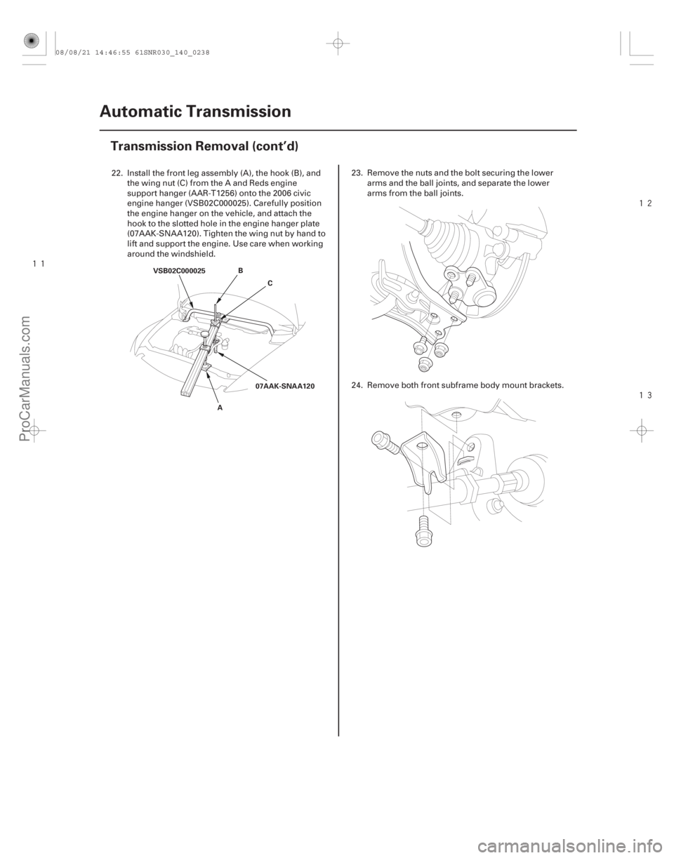
22. Install the front leg assembly (A), the hook (B), andthe wing nut (C) from the A and Reds engine
support hanger (AAR-T 1256) onto the 2006 civic
engine hanger (VSB02C000025). Carefully position
the engine hanger on the vehicle, and attach the
hook to the slotted hole in the engine hanger plate
(07AAK-SNAA120). Tighten the wing nut by hand to
lift and support the engine. Use care when working
around the windshield. 23. Remove the nuts and the bolt securing the lower
arms and the ball joints, and separate the lower
arms from the ball joints.
24. Remove both front subframe body mount brackets.
08/08/21 14:46:55 61SNR030_140_0238
ProCarManuals.com
DYNOMITE -2009-