Page 1302 of 2893
����
����� �
�
�
��
16-9
A
B
C
B
K20Z2 engine model: 22 x 1.5 mm 07XAC-001010A
K20Z3 engine model: 24 x 1.5 mm 07XAC-001020A AC A
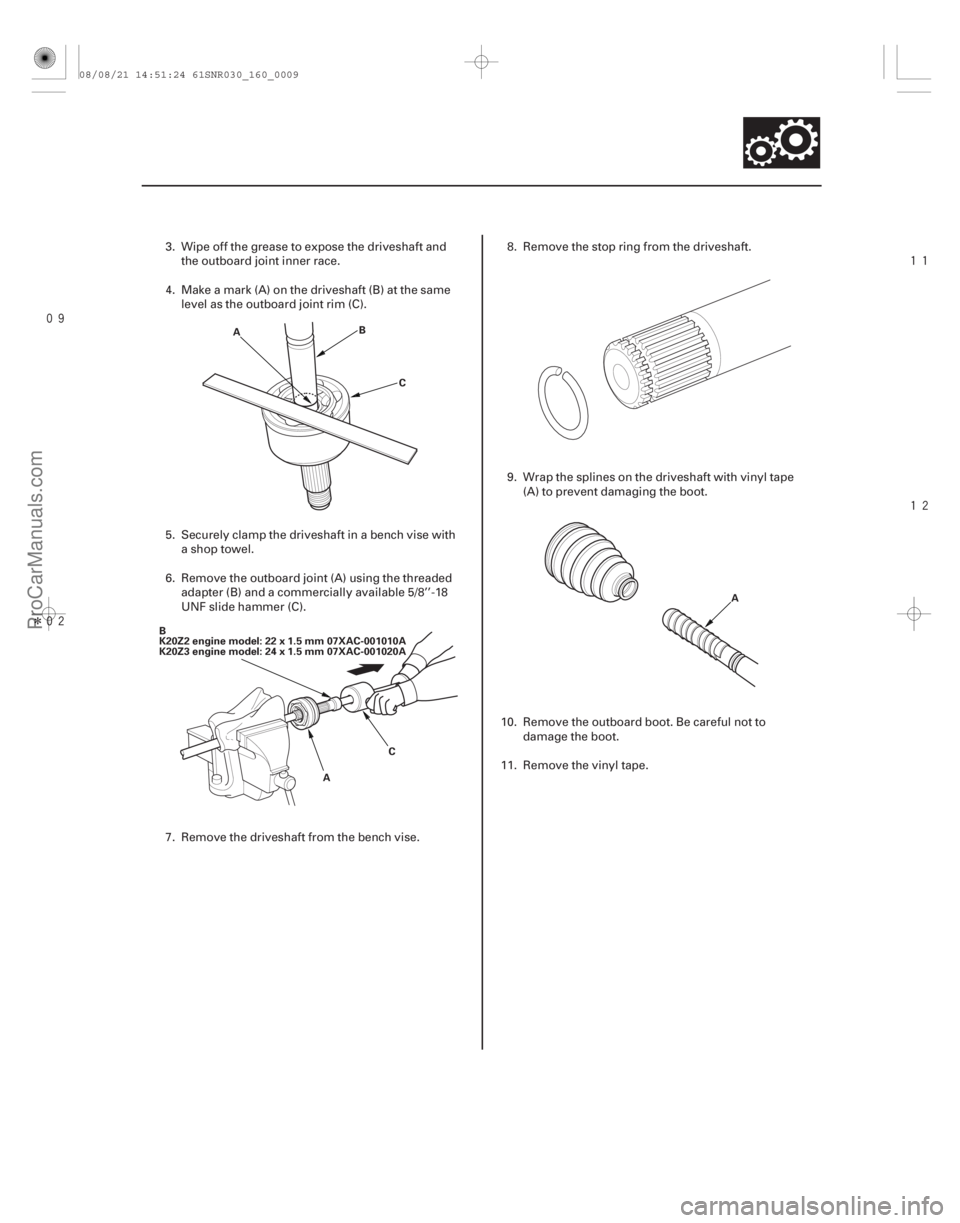
3. Wipe off the grease to expose the driveshaft and
the outboard joint inner race.
4. Make a mark (A) on the driveshaft (B) at the same level as the outboard joint rim (C).
5. Securely clamp the driveshaft in a bench vise with a shop towel.
6. Remove the outboard joint (A) using the threaded adapter (B) and a commercially available 5/8’’-18
UNF slide hammer (C).
7. Remove the driveshaft from the bench vise. 8. Remove the stop ring from the driveshaft.
9. Wrap the splines on the driveshaft with vinyl tape
(A) to prevent damaging the boot.
10. Remove the outboard boot. Be careful not to damage the boot.
11. Remove the vinyl tape.
08/08/21 14:51:24 61SNR030_160_0009
ProCarManuals.com
DYNOMITE -2009-
Page 1303 of 2893
�µ�µ
�µ �µ
����
�����
�����
�����
�(�#�'�����������
��������������������� �����)����
K20Z2 engine model (left driveshaft only)
K20Z3 engine model
K20Z2 engine model
K20Z3 engine model
Model Left/Right Driveshaft Specified Length (A)
16-10Driveline/Axle
Dynamic Damper Replacement
A
A A
A
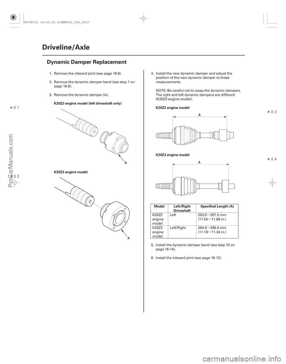
1. Remove the inboard joint (see page 16-6).
2. Remove the dynamic damper band (see step 1 on page 16-6).
3. Remove the dynamic damper (A). 4. Install the new dynamic damper and adjust the
position of the new dynamic damper to these
measurements.
NOTE: Be careful not to swap the dynamic dampers.
The right and left dynamic dampers are different
(K20Z3 engine model).
K20Z2
engine
model Left 293.0 297.0 mm
(11.54 11.69 in.)
K20Z3
engine
model Left/Right 284.0 288.0 mm
(11.18 11.34 in.)
5. Install the dynamic damper band (see step 10 on page 16-14).
6. Install the inboard joint (see page 16-12).
08/08/21 14:51:25 61SNR030_160_0010
ProCarManuals.com
DYNOMITE -2009-
Page 1304 of 2893
����
�(�#�'�����������
���������������������!�����)����
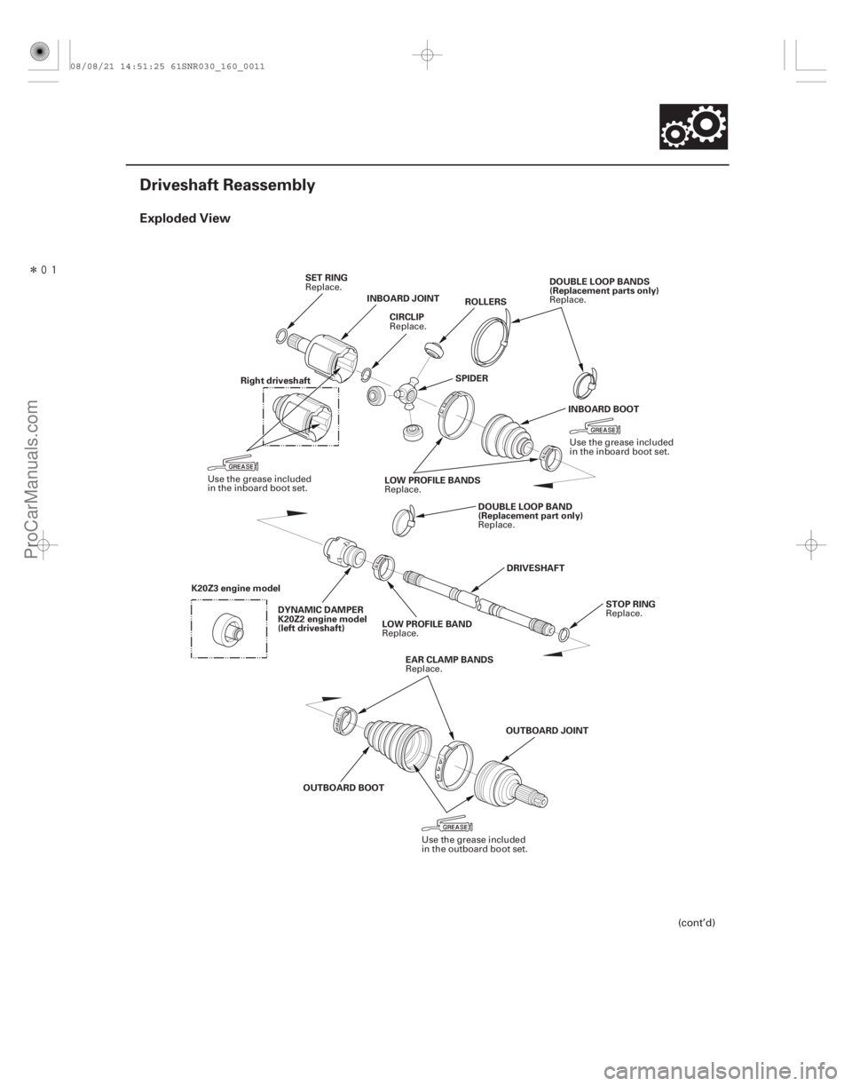
Exploded View
16-11
Driveshaft Reassembly
SET RINGINBOARD JOINT ROLLERS
SPIDER DOUBLE LOOP BANDS
(Replacement parts only)
INBOARD BOOT
LOW PROFILE BANDS DOUBLE LOOP BAND
(Replacement part only)
DRIVESHAFT STOP RING
LOW PROFILE BAND
DYNAMIC DAMPER
K20Z2 engine model
(left driveshaft)
OUTBOARD BOOT OUTBOARD JOINT
EAR CLAMP BANDS
CIRCLIP
Right driveshaft
K20Z3 engine model
(cont’d)
Replace. Replace.
Use the grease included
in the inboard boot set.
Replace.
Use the grease included
in the inboard boot set.
Replace.
Replace.
Replace.
Replace.
Use the grease included
in the outboard boot set.
Replace.
08/08/21 14:51:25 61SNR030_160_0011
ProCarManuals.com
DYNOMITE -2009-
Page 1306 of 2893
����
��������
�µ �µ
�µ �µ
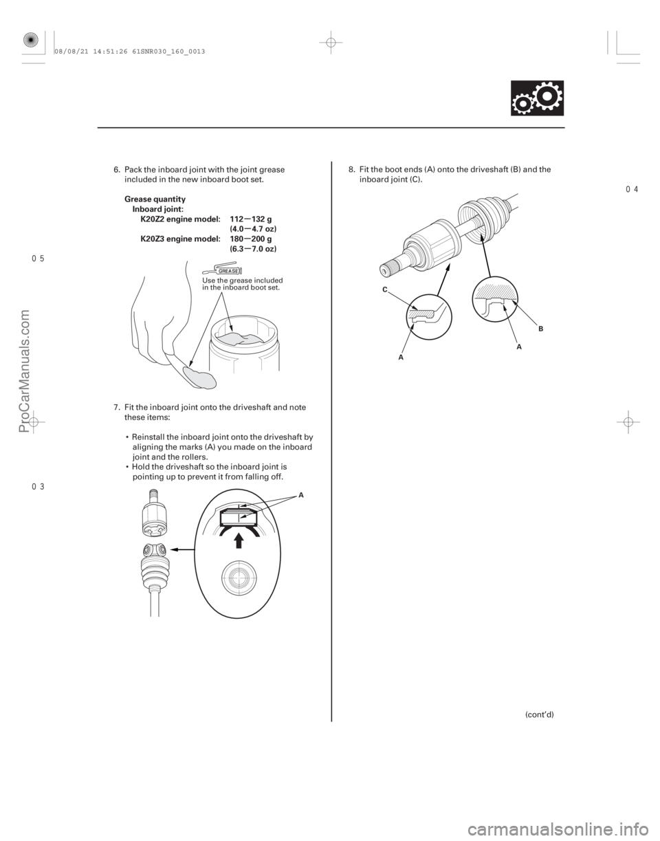
Grease quantity
Inboard joint:K20Z2 engine model: 112 132 g (4.0 4.7 oz)
K20Z3 engine model: 180 200 g (6.3 7.0 oz)
16-13
A A
B
C
A
6. Pack the inboard joint with the joint greaseincluded in the new inboard boot set.
7. Fit the inboard joint onto the driveshaft and note these items:
Reinstall the inboard joint onto the driveshaft by aligning the marks (A) you made on the inboard
joint and the rollers.
Hold the driveshaft so the inboard joint is pointing up to prevent it from falling off. 8. Fit the boot ends (A) onto the driveshaft (B) and the
inboard joint (C).
(cont’d)
Use the grease included
in the inboard boot set.
08/08/21 14:51:26 61SNR030_160_0013
ProCarManuals.com
DYNOMITE -2009-
Page 1307 of 2893

16-14Driveline/Axle
Driveshaft Reassembly (cont’d)")
�µ�µ
�µ �µ
�µ �µ
�µ �µ �µ
�µ
�����
�����
����
����
Left driveshaft
Right driveshaft
Model Left/Right Driveshaft Specified Length (A)
16-14Driveline/Axle
Driveshaft Reassembly (cont’d)
A
A A
B C
A B
9. Adjust the length (A) of the driveshaft to the figure
as shown, then adjust the boots to halfway
between full compression and full extension. Bleed
excess air from the boots by inserting a flat-tipped
screwdriver between the boot and the joint.
K20Z2
engine
model Left 505.5 510.0 mm
(19.88 20.08 in.)
Right 493.0 498.0 mm (19.41 19.61 in.)
K20Z3
engine
model Left 511.0 516.0 mm
(20.12 20.31 in.)
Right 486.8 491.8 mm (19.17 19.36 in.)
10. Install new boot bands.
For the double loop type, go to step 11.
For the low profile type, go to step 20. 11. Fit the boot ends onto the driveshaft and the
inboard joint, then install a new double loop band
(A) onto the boot (B).
NOTE: Pass the end of the new double loop band
through the clip (C) twice in the direction of the
forward rotation of the driveshaft.
12. Pull up the slack in the band by hand.
13. Mark a position (A) on the band 10 14 mm (0.4 0.6 in.) from the clip (B).
Replace.
08/08/21 14:51:27 61SNR030_160_0014
ProCarManuals.com
DYNOMITE -2009-
Page 1311 of 2893

K20Z3 engine model: 110 130 g (3.8 4.5 oz)
16-18Driveline/Axle
Driveshaft Reassem")
�
��
����� ���
�
��
�µ
�µ
�µ �µ
Total grease quantity
Outboard joint:K20Z2 engine model: 120 140 g (4.2 4.9 oz)
K20Z3 engine model: 110 130 g (3.8 4.5 oz)
16-18Driveline/Axle
Driveshaft Reassembly (cont’d)
10 cm
(4 in.)
A
B A A
B
C A
A
7. To completely seat the outboard joint, pick up the driveshaft and joint, and tap or hit the assembly
onto a hard surface from a height of about 10 cm
(4 in.).
NOTE: Do not use a hammer as excessive force
may damage the driveshaft. Be careful not to
damage the threaded section (A) of the outboard
joint.
8. Check the alignment of the paint mark (A) you made with the outboard joint end (B).
To avoid driveshaft and vehicle damage, the
shaft must be all the way into the outboard
joint to ensure the stop ring is properly
seated. 9. Pack the outboard joint (A) with the remaining
grease included in the new outboard boot set.
10. Fit the boot ends (A) onto the driveshaft (B) and outboard joint (C). Bleed any excess air from the
boot by inserting a flat-tipped screwdriver between
the boot and the joint.
Use the grease included
in the outboard boot set.
08/08/21 14:51:29 61SNR030_160_0018
ProCarManuals.com
DYNOMITE -2009-
Page 1312 of 2893
�µ�µ
�µ �µ
�µ �µ
�µ �µ
�����
��
��
����
�
��
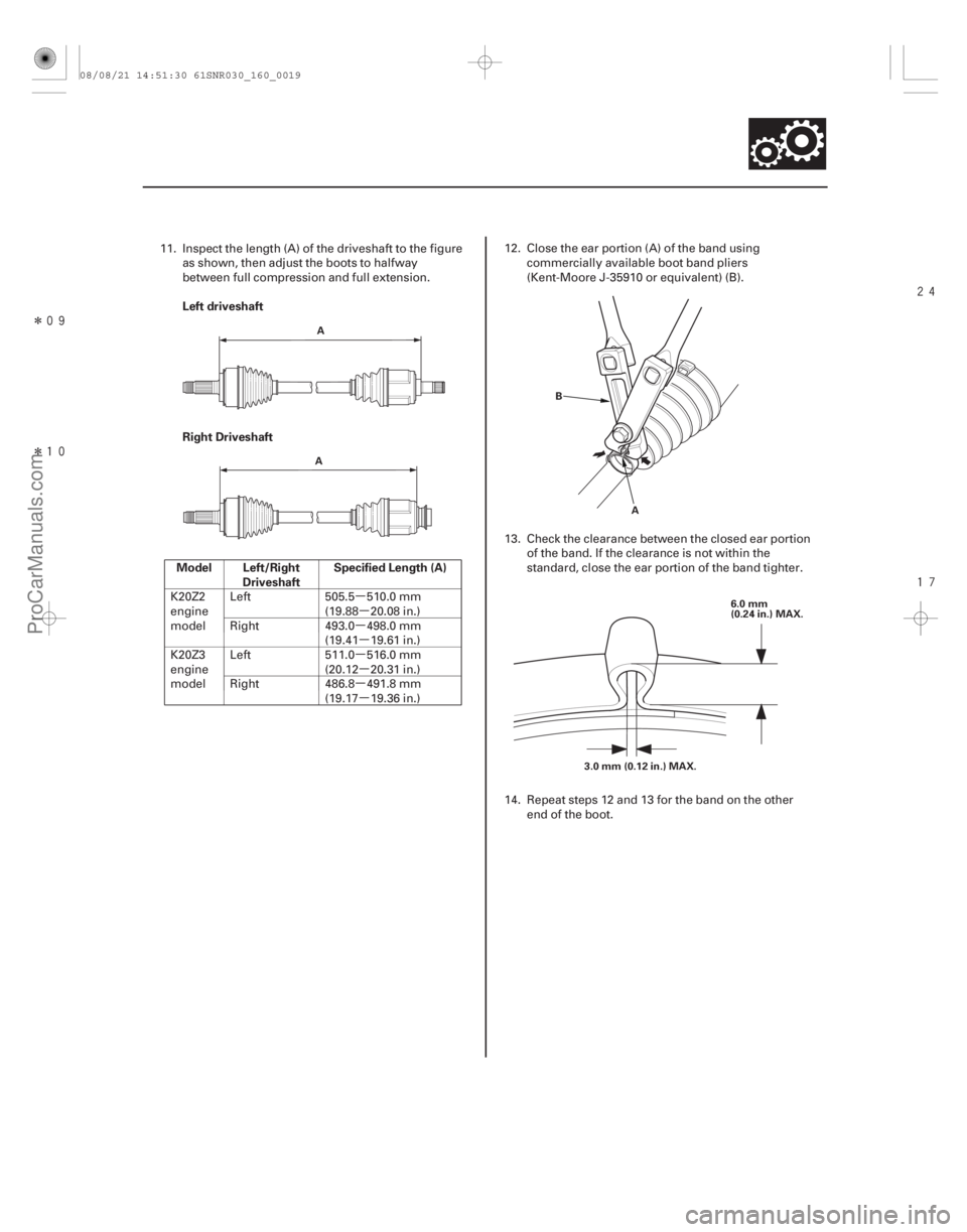
Left driveshaft
Right Driveshaft
Model Left/Right Driveshaft Specified Length (A)
16-19
A
A B
A 6.0 mm
(0.24 in.) MAX.
3.0 mm (0.12 in.) MAX.
11. Inspect the length (A) of the driveshaft to the figure as shown, then adjust the boots to halfway
between full compression and full extension.
K20Z2
engine
model Left 505.5 510.0 mm
(19.88 20.08 in.)
Right 493.0 498.0 mm (19.41 19.61 in.)
K20Z3
engine
model Left 511.0 516.0 mm
(20.12 20.31 in.)
Right 486.8 491.8 mm (19.17 19.36 in.) 12. Close the ear portion (A) of the band using
commercially available boot band pliers
(Kent-Moore J-35910 or equivalent) (B).
13. Check the clearance between the closed ear portion of the band. If the clearance is not within the
standard, close the ear portion of the band tighter.
14. Repeat steps 12 and 13 for the band on the other end of the boot.
08/08/21 14:51:30 61SNR030_160_0019
ProCarManuals.com
DYNOMITE -2009-
Page 1313 of 2893
���� �µ�µ
�µ�µ
Grease quantity
K20Z2 engine model: 0.5 1.0 g (0.02 0.04 oz)
K20Z3 engine model: 2.0 3.0 g (0.08 0.12 oz)")
�µ
���
���� ����
�����
�(�#�'�����������
��������������������� �����)���� �µ�µ
�µ�µ
Grease quantity
K20Z2 engine model: 0.5 1.0 g (0.02 0.04 oz)
K20Z3 engine model: 2.0 3.0 g (0.08 0.12 oz)
16-20Driveline/Axle
Driveshaft Installation
(P/N 08734-0001) A
A B A
B
A
(P/N 08798-9002)
NOTE: Before starting installation, make sure the
mating surfaces of the joint and the splined section are
clean.
1. Apply about 5 g (0.18 oz) moly 60 paste (P/N 08734-0001) to the contact area (A) of the
outboard joint and the front wheel bearing.
NOTE: The paste helps to prevent noise and
vibration.
2. Install a new set ring (A) onto the set ring groove (B) of the driveshaft (left driveshaft). 3. Install a new set ring (A) onto the set ring groove
(B) of the intermediate shaft.
4. Apply super high temp urea grease (P/N 08798-9002) to the whole splined surface (A) of
the right driveshaft. After applying grease, remove
the grease from the splined grooves at intervals of
2 3 splines and from the set ring groove (B) so
that air can bleed from the intermediate shaft.
Replace.
08/08/21 14:51:31 61SNR030_160_0020
ProCarManuals.com
DYNOMITE -2009-