Page 1373 of 2893
���
�µ
�µ
�µ
�µ �µ
�µ
�µ
�µ
DTC 51-02:
DTC 51-03:
DTC 51-06:
DTC 51-07:
YES
NO
YES
NO YES
NO
YES
NO
17-50EPS Components
DTC Tro")
�µ
�µ
���
����
�(�#�'��������� �������������'���
�����������)���
�µ
�µ
�µ
�µ �µ
�µ
�µ
�µ
DTC 51-02:
DTC 51-03:
DTC 51-06:
DTC 51-07:
YES
NO
YES
NO YES
NO
YES
NO
17-50EPS Components
DTC Troubleshooting (cont’d)
EPS CONTROL UNIT CONNECTOR D (28P)
PVF (BRN) VS1 (GRN)
EPS CONTROL UNIT CONNECTOR D (28P)
PVF (BRN)
VS2 (LT GRN)
Torque Sensor (VT3 Differential-
amplification Function) (Regular Diagnosis)
Torque Sensor (VT1, VT2 Rapid
Change) (Regular Diagnosis)
Torque Sensor (VT1, VT2
Average) (Regular Diagnosis)
Torque Sensor (VT1, VT2 Initial
Check) (Initial Diagnosis)
1. Turn the ignition switch to ON (II).
2. Clear the DTC with the HDS.
3. Turn the ignition switch to LOCK (0).
4. Start the engine.
Go to step 5.
Check for loose terminals or poor connections.
If the connections are good, the system is OK at
this time.
5. Check for DTCs with the HDS.
Go to step 6.
Troubleshoot the indicated DTC. If there are
no DTCs, the system is OK at this time.
6. Turn the ignition switch to LOCK (0). 7. Disconnect EPS control unit connector D (28P).
8. Measure the resistance between EPS control unit
connector D (28P) terminals No. 9 and No. 10.
Go to step 9.
Go to step 13.
9. Measure the resistance between EPS control unit connector D (28P) terminals No. 8 and No. 9.
Go to step 10.
Go to step 15.
Wire side of female terminals
Wire side of female terminals
Does t he E PS i nd i cat or come on?
I s DT C 5 1-02, 5 1-03, 5 1-06, or 5 1-07 i nd i cat ed ? Is t he r esi st ance bet w een 12 15 ?
Is t he r esi st ance bet w een 12 15 ?
08/08/21 14:54:35 61SNR030_170_0051
ProCarManuals.com
DYNOMITE -2009-
Page 1376 of 2893
����
�µ
�µ
�µ
�µ �µ
�µ
DTC 61-04:
YES
NO
YES
NO YES
NO
17-53
EPS CONTROL UNIT
CONNECTOR B
EPS CONTROL UNIT
CONNECTOR C
No. 1
No. 2
No. 1
No.")
����
�(�#�'��������� �������������'���
�����������)����
�µ
�µ
�µ
�µ �µ
�µ
DTC 61-04:
YES
NO
YES
NO YES
NO
17-53
EPS CONTROL UNIT
CONNECTOR B
EPS CONTROL UNIT
CONNECTOR C
No. 1
No. 2
No. 1
No. 2
No. 1
No. 1
EPS CONTROL UNIT CONNECTOR B (2P)
H-V (BLU)
H-U (RED) H-W (GRN)
EPS CONTROL UNIT CONNECTOR C (2P)
Open/Short in EPS Motor Harness
(Steering Diagnosis)
1. Turn the ignition switch to ON (II).
2. Clear the DTC with the HDS.
3. Turn the ignition switch to LOCK (0).
4. Start the engine.
5. Turn the steering wheel to the right or left, and wait
10 seconds or more.
Go to step 6.
Check for loose terminals or poor connections.
If the connections are good, the system is OK at
this time.
6. Check for DTCs with the HDS.
Go to step 7.
Troubleshoot the indicated DTC. If there are
no DTCs, the system is OK at this time.
7. Turn the ignition switch to LOCK (0).
8. Disconnect the EPS control unit connector B (2P) and connector C (2P). 9. Check for continuity between the following
terminals of the EPS control unit connector B (2P)
and connector C (2P).
Go to step 10.
Go to step 13.
(cont’d)
Wire side of female terminals
Wire side of female terminals
Does t he E PS i nd i cat or come on? Is DT C 61-04 indicated? Is there continuity?
08/08/21 14:54:36 61SNR030_170_0054
ProCarManuals.com
DYNOMITE -2009-
Page 1378 of 2893
����
�µ
�µ �µ
�µ
�µ
�µ
YES
NO
YES
NO
YES
NO
DTC 71-01:
DTC 71-02:
DTC 71-03:
DTC 71-05:
DTC 71-06:
17-5517-55
No. 1
No. 2
No. 1
No. 2
H-W (R")
�����
�(�#�'��������� �������������'���
���
�������)����
�µ
�µ �µ
�µ
�µ
�µ
YES
NO
YES
NO
YES
NO
DTC 71-01:
DTC 71-02:
DTC 71-03:
DTC 71-05:
DTC 71-06:
17-5517-55
No. 1
No. 2
No. 1
No. 2
H-W (RED)
H-U (BLK)
H-V (WHT)
EPS MOTOR
1P CONNECTOR
EPS MOTOR
2P CONNECTOR
No. 1
No. 1
EPS MOTOR 2P CONNECTOR
EPS MOTOR 1P CONNECTOR
13. Disconnect the EPS motor 1P connector and the
EPS motor 2P connector.
14. On the EPS motor side, check for continuity between the following terminals of the EPS motor
1P and the EPS motor 2P connector.
Repair open in the wire between the EPS
control unit and the EPS motor.
Open in the EPS motor wire, or EPS motor
internal circuit, replace the EPS motor (see page
17-63). 1. Turn the ignition switch to ON (II).
2. Clear the DTC with the HDS.
3. Turn the ignition switch to LOCK (0).
4. Start the engine.
5. Turn the steering wheel to the right or left, and wait
10 seconds or more.
Go to step 6.
Check for loose terminals or poor connections.
If the connections are good, the system is OK at
this time.
6. Check for DTCs with the HDS.
Go to step 7.
Troubleshoot the indicated DTC. If there are
no DTCs, the system is OK at this time.
7. Turn the ignition switch to LOCK (0).
8. Disconnect EPS control unit connector D (28P).
(cont’d)EPS Motor Angle Sensor (SIN/
COS Signals) (Steering Diagnosis)
EPS Motor Angle Sensor (Neutral
Position Learning of SIN/COS) (Initial
Diagnosis)
EPS Motor Angle Sensor (SIN/
COS Signals) (Steering Diagnosis)
EPS Motor Angle Sensor (SIN/
COS Signals Charging Amount) (Steering
Diagnosis)
EPS Motor Angle Sensor (Neutral
Position of SIN/COS) (Initial Diagnosis)
Terminal side of male terminal
Terminal side of male terminals
Is there continuity? Does t he E PS i nd i cat or come on?
Is DT C 7 1-01, 7 1-02, 7 1-03, 7 1-05 or 7 1-06indicated?
08/08/21 14:54:37 61SNR030_170_0056
ProCarManuals.com
DYNOMITE -2009-
Page 1381 of 2893
����
�µ
�µ
�µ
�µ �µ
�µ
�µ
�µ
DTC 71-04:
YES
NO
YES
NO YES
NO
YES
NO
17-58EPS Components
DTC Troubleshooting (cont’d)
EPS CONTROL U")
�µ
���
����
�(�#�'��������� �������������'���
�����������)����
�µ
�µ
�µ
�µ �µ
�µ
�µ
�µ
DTC 71-04:
YES
NO
YES
NO YES
NO
YES
NO
17-58EPS Components
DTC Troubleshooting (cont’d)
EPS CONTROL UNIT CONNECTOR D (28P)
R1 (BLU)
R2 (PNK)
EPS CONTROL UNIT CONNECTOR D (28P) R1 (BLU)
R2 (PNK)
EPS Motor Angle Sensor (Check
Signals) (Regular Diagnosis)
1. Turn the ignition switch to ON (II).
2. Clear the DTC with the HDS.
3. Turn the ignition switch to LOCK (0).
4. Start the engine.
5. Turn the steering wheel to the right or left, and wait
10 seconds or more.
Go to step 6.
Check for loose terminals or poor connections.
If the connections are good, the system is OK at
this time.
6. Check for DTCs with the HDS.
Go to step 7.
Troubleshoot the indicated DTC. If there are
no DTCs, the system is OK at this time.
7. Turn the ignition switch to LOCK (0).
8. Disconnect the EPS control unit connector D (28P). 9. Measure the resistance between the EPS control
unit connector D (28P) terminal No. 13 and No. 27.
Go to step 10.
Go to step 13.
10. Check for continuity between body ground and the EPS control unit connector D (28P) terminal No. 13
and the terminal No. 27 individually.
Go to step 11.
Check for loose terminals in the EPS control
unit connectors, and repair if necessary. If no poor
connections are found, replace the EPS control unit
(see page 17-84).
Wire side of female terminals
Wire side of female terminalsDoes t he E PS i nd i cat or come on?
Is DTC 71-04 indicated? Is t he r esi st ance bet w een 13 25 ?
Is there continuity?
08/08/21 14:54:38 61SNR030_170_0059
ProCarManuals.com
DYNOMITE -2009-
Page 1388 of 2893
����
Special Tools Required
Removal
17-65
Steering Gearbox Removal and Installation
A
Ball joint remover, 28 mm 07MAC-SL0A202
Engine hang")
�Ì
�Ï ���
�(�#�'�����������
���
�����������
�
�
� �����)����
Special Tools Required
Removal
17-65
Steering Gearbox Removal and Installation
A
Ball joint remover, 28 mm 07MAC-SL0A202
Engine hanger adapter
VSB02C000015
Front subframe adaptor VSB02C000016
2006 Civic engine hanger VSB02C000025
Engine support hunger, A and Reds AAR-T1256 : These special tools are available through Honda
Canada Inc. Technical Tools Department; FAX 866-
398-8665/e-mail: ch_technicaltools ch. honda. com
Note these items during removal: Use solvent and a brush, wash any oil and dirt off the end of the steering gearbox. Avoid any electrical
parts. Blow dry with compressed air.
Be sure to remove the steering wheel before disconnecting the steering joint, or damage to the
cable reel may occur.
1. Do the battery terminal disconnection procedure (see page 22-68).
2. Raise the front of the vehicle, and support it with safety stands in the proper locations (see page
1-11).
3. Remove the front wheels.
4. Remove the driver’s airbag (see page 24-188), and the steering wheel (see page 17-6).
5. Remove the driver’s dashboard undercover (see page 20-103). 6. Remove the steering joint cover (A).
(cont’d)
08/08/21 14:55:09 61SNR030_170_0066
ProCarManuals.com
DYNOMITE -2009-
Page 1390 of 2893
to the th")
����
��������
�����
17-67
VSB02C000015
VSB02C000025 B
C
A D
VSB02C000015
AAR-T1256 07MAC-SL0A202
A
B
12 x 1.25 mm 07AAF-SDAA100
D C
AB
15. Attach the engine hanger adapter (VSB02C000015)to the threaded hole in the cylinder head.
16. Install the front leg assembly (A), hook (B), and wing nut (C) from an A and Reds engine support
hanger (AAR-T1256) onto the 2006 Civic engine
hanger (VSB02C000025). Carefully position the
engine hanger on the vehicle, and attach the hook
to the forward hole in the engine hanger adapter
(D). Tighten the wing nut by hand to lift and support
the engine/transmission assembly.
NOTE: Use care when working around the
windshield. 17. Remove the cotter pin (A) from the 12 mm nut (B),
and loosen the nut.
18. Separate the tie-rod ball joint and the knuckle using the ball joint remover (see page 18-12).
19. Remove the front splash shield (see page 20-172).
20. Disconnect the EPS motor connector A (2P), the EPS motor connector B (1P), torque sensor 4P
connector (C), the EPS motor angle sensor 6P
connector (D), from passenger’s side of the
steering gearbox. Wrap the connectors with vinyl
tape to avoid contamination from grease or water.
(cont’d)
Replace.
08/08/21 14:55:10 61SNR030_170_0068
ProCarManuals.com
DYNOMITE -2009-
Page 1393 of 2893
�
��
�
���
�
�
��
17-70EPS Components
Steering Gearbox Removal and Installation (cont’d)
A
B
A
12x1.25mm A
14x1.5mm
A
14x1.5mm
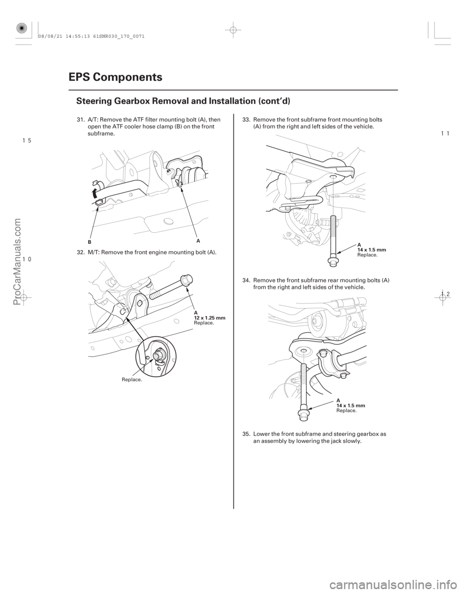
31. A/T: Remove the ATF filter mounting bolt (A), then open the ATF cooler hose clamp (B) on the front
subframe.
32. M/T: Remove the front engine mounting bolt (A). 33. Remove the front subframe front mounting bolts
(A) from the right and left sides of the vehicle.
34. Remove the front subframe rear mounting bolts (A) from the right and left sides of the vehicle.
35. Lower the front subframe and steering gearbox as an assembly by lowering the jack slowly.
Replace. Replace. Replace.
Replace.
08/08/21 14:55:13 61SNR030_170_0071
ProCarManuals.com
DYNOMITE -2009-
Page 1397 of 2893
����
�����
��
����
17-74EPS Components
Steering Gearbox Removal and Installation (cont’d)
A
14x1.5mm
103 N·m
(10.5 kgf·m,
75.9 lbf·ft)
A
14x1.5mm
103 N·m
(10.5 kgf·m,
75.9 lbf·ft) B
12x1.25mm
64 N·m
(6.5 kgf·m, 47 lbf·ft)
A
B A
6x1.0mm
12 N·m
(1.2 kgf·m,
8.7 lbf·ft)
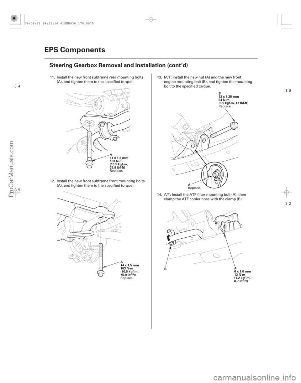
11. Install the new front subframe rear mounting bolts
(A), and tighten them to the specified torque.
12. Install the new front subframe front mounting bolts (A), and tighten them to the specified torque. 13. M/T: Install the new nut (A) and the new front
engine mounting bolt (B), and tighten the mounting
bolt to the specified torque.
14. A/T: Install the ATF filter mounting bolt (A), then clamp the ATF cooler hose with the clamp (B).
Replace.
Replace. Replace.
Replace.
08/08/21 14:55:16 61SNR030_170_0075
ProCarManuals.com
DYNOMITE -2009-