Page 1949 of 2893
���� ���
�(�#������������
�������������������
� �����)����
21-6921-69
Sunlight Sensor Test Sunlight Sensor Replacement
REDPUR
A
A
B")
�´
�µ
�µ
�µ
���
�(�#�'�����������
�������������������
�������)���� ���
�(�#�'�����������
�������������������
� �����)����
21-6921-69
Sunlight Sensor Test Sunlight Sensor Replacement
REDPUR
A
A
B
1. Remove the sunlight sensor (A) from thedashboard (see page 21-69).
2. Turn the ignition switch to ON (II). Measure the voltage between the terminals with the ( ) probe
on terminal No. 2 and the ( ) probe on terminal
No. 1 with the connector connected.
NOTE: The voltage readings will not change under
the light of a flashlight or a fluorescent lamp.
Voltage should be: 3.6 3.7 V or more with the sensor out of direct sunlight.
3.3 3.5 V or less with the sensor in direct sunlight.
3. If the voltage is not as specified, replace the sunlight sensor (see page 21-69). 1. Remove the gauge control module (SPEEDO)
(see page 22-277).
2. Remove the sunlight sensor (A) from the dashboard with a flat-tip screwdriver, then
disconnect the connector (B). Be careful not to
damage the sensor and the dashboard.
3. Install the sensor in the reverse order of removal.
08/08/21 14:43:35 61SNR030_210_0070
ProCarManuals.com
DYNOMITE -2009-
Page 1950 of 2893
���
���
�(�#�'�����������
���
���������������
�������)����
21-70 Climate Control
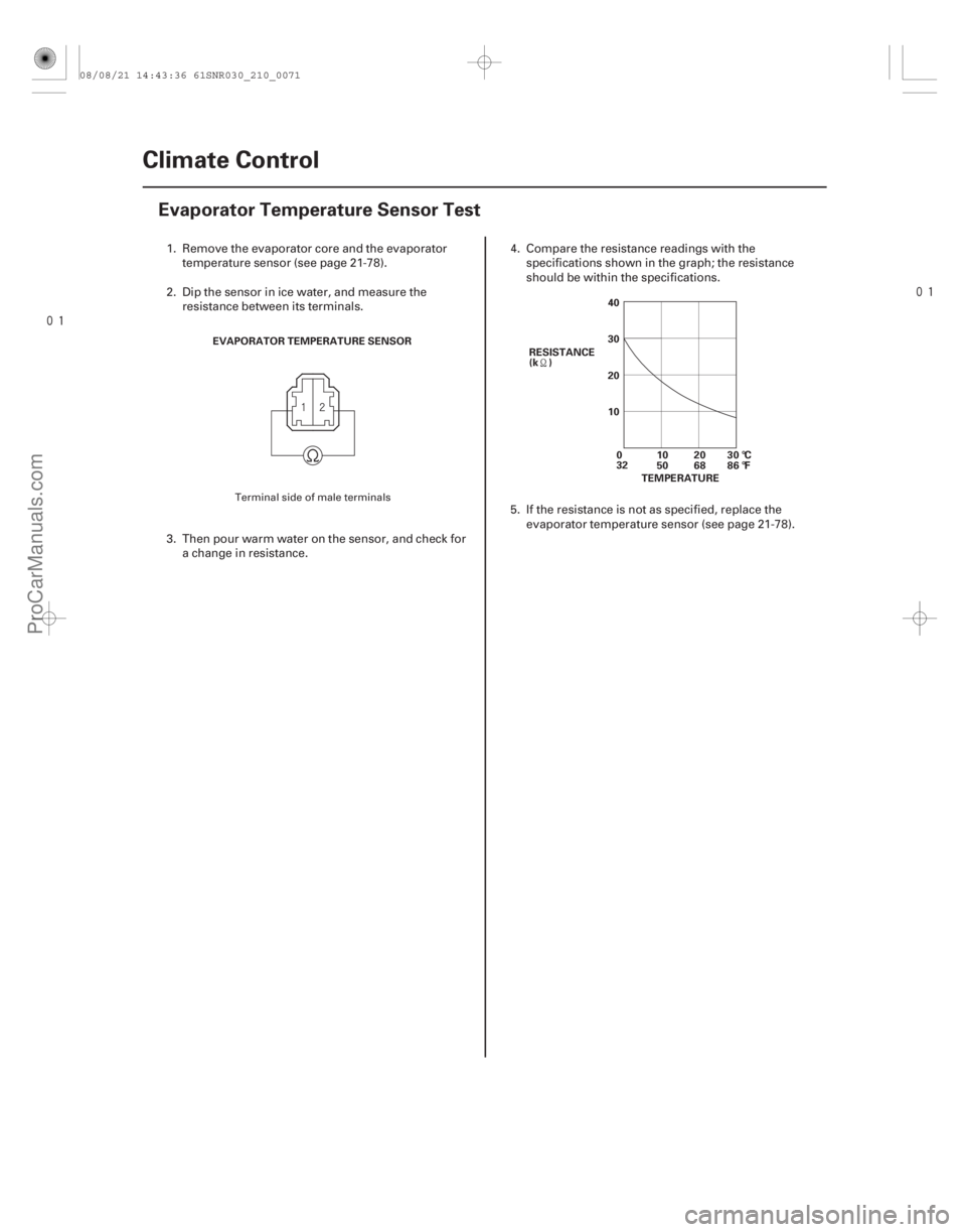
Evaporator Temperature Sensor Test
EVAPORATOR TEMPERATURE SENSOR
40
30
20
10
RESISTANCE
(k )
10
5020
6830 °C
86 °F
TEMPERATURE
0
32
1. Remove the evaporator core and the evaporator
temperature sensor (see page 21-78).
2. Dip the sensor in ice water, and measure the resistance between its terminals.
3. Then pour warm water on the sensor, and check for a change in resistance. 4. Compare the resistance readings with the
specifications shown in the graph; the resistance
should be within the specifications.
5. If the resistance is not as specified, replace the evaporator temperature sensor (see page 21-78).
Terminal side of male terminals
08/08/21 14:43:36 61SNR030_210_0071
ProCarManuals.com
DYNOMITE -2009-
Page 1959 of 2893
���
��������
����
�(�#�'�����������
���
�������������
�
� �����)����
21-78 Climate Control
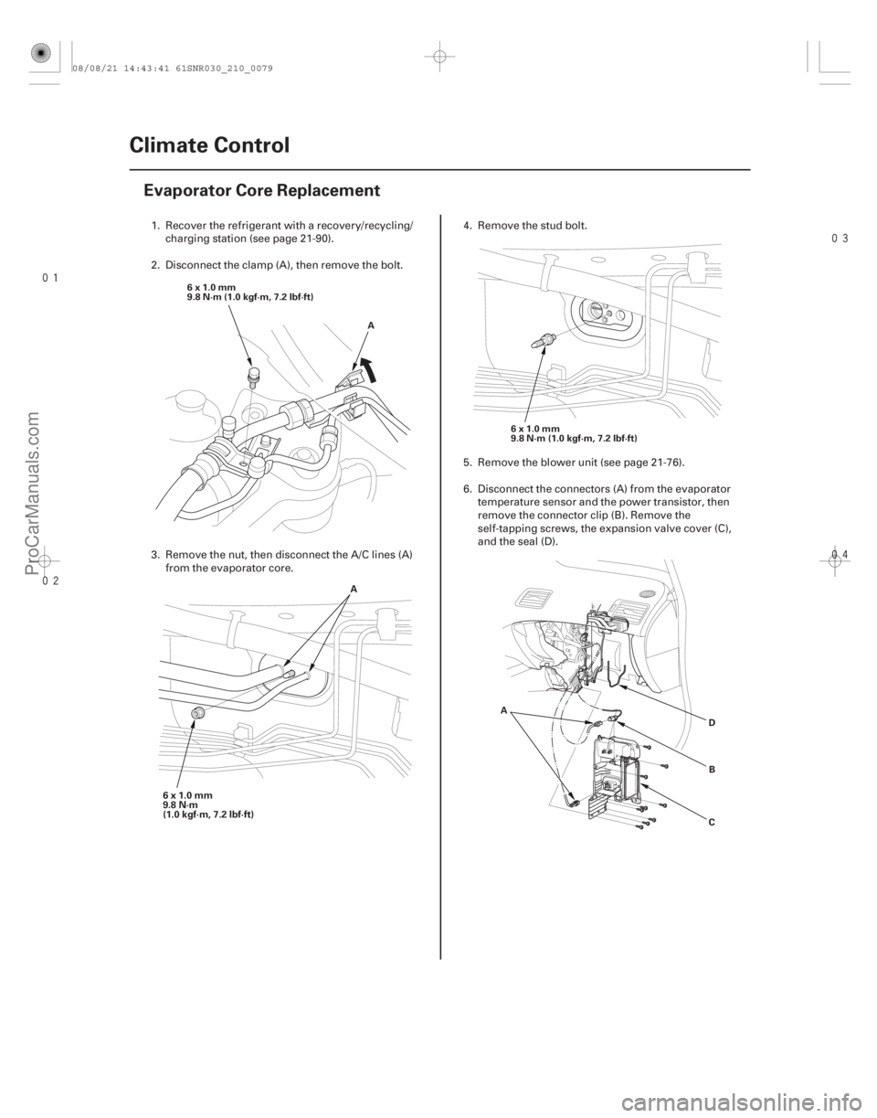
Evaporator Core Replacement
A
6x1.0mm
9.8 N·m (1.0 kgf·m, 7.2 lbf·ft)
6x1.0mm
9.8 N·m (1.0 kgf·m, 7.2 lbf·ft)
A B
C
D
6x1.0mm
9.8 N·m
(1.0 kgf·m, 7.2 lbf·ft) A
1. Recover the refrigerant with a recovery/recycling/
charging station (see page 21-90).
2. Disconnect the clamp (A), then remove the bolt.
3. Remove the nut, then disconnect the A/C lines (A) from the evaporator core. 4. Remove the stud bolt.
5. Remove the blower unit (see page 21-76).
6. Disconnect the connectors (A) from the evaporator
temperature sensor and the power transistor, then
remove the connector clip (B). Remove the
self-tapping screws, the expansion valve cover (C),
and the seal (D).
08/08/21 14:43:41 61SNR030_210_0079
ProCarManuals.com
DYNOMITE -2009-
Page 1960 of 2893
 229.5 mm
(9.04 in.)
A
B
7. Carefully pull out the evaporator core (A) withoutbending the lines, then remove the plate (B).
8. Remove the clips (A) and the evaporato")
����
����
21-79
BA
94 mm
(3.70 in.) 229.5 mm
(9.04 in.)
A
B
7. Carefully pull out the evaporator core (A) withoutbending the lines, then remove the plate (B).
8. Remove the clips (A) and the evaporator temperature sensor (B). 9. Install the core in the reverse order of removal, and
note these items:
If you’re installing a new evaporator core, add refrigerant oil (SP-10) (see page 21-7).
Replace the O-rings with new ones at each fitting, and apply a thin coat of refrigerant oil before
installing them. Be sure to use the correct O-rings
for HFC-134a (R-134a) to avoid leakage.
Immediately after using the oil, reinstall the cap on the container, and seal it to avoid moisture
absorption.
Do not spill the refrigerant oil on the vehicle; it may damage the paint; if the refrigerant oil
contacts the paint, wash it off immediately.
Make sure that there is no air leakage.
Charge the system (see page 21-92).
08/08/21 14:43:42 61SNR030_210_0080
ProCarManuals.com
DYNOMITE -2009-
Page 1963 of 2893
����
��������
����
21-82Climate Control
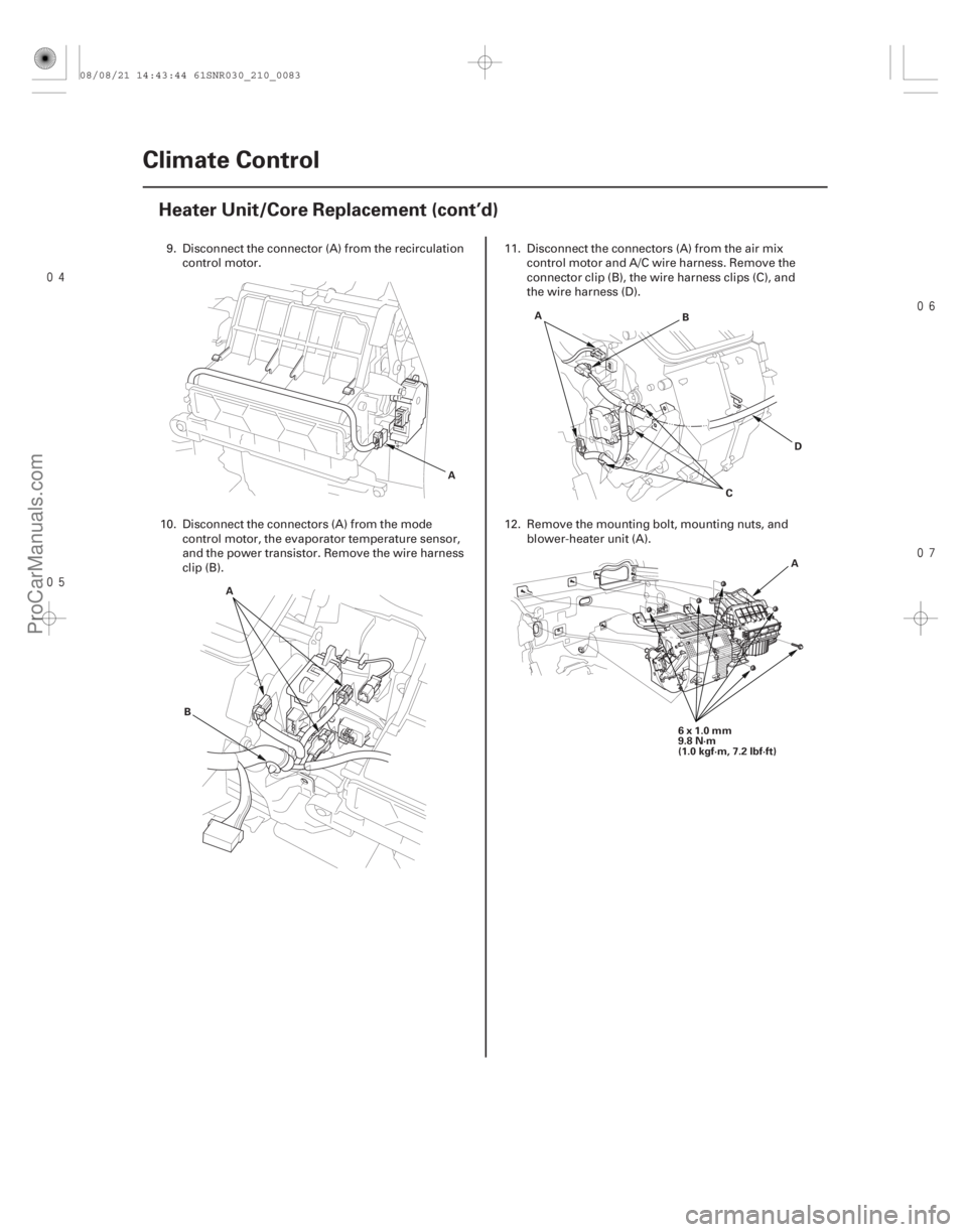
Heater Unit/Core Replacement (cont’d)
A
A
B B
C D
A
6x1.0mm
9.8 N·m
(1.0 kgf·m, 7.2 lbf·ft)A
9. Disconnect the connector (A) from the recirculation
control motor.
10. Disconnect the connectors (A) from the mode control motor, the evaporator temperature sensor,
and the power transistor. Remove the wire harness
clip (B). 11. Disconnect the connectors (A) from the air mix
control motor and A/C wire harness. Remove the
connector clip (B), the wire harness clips (C), and
the wire harness (D).
12. Remove the mounting bolt, mounting nuts, and blower-heater unit (A).
08/08/21 14:43:44 61SNR030_210_0083
ProCarManuals.com
DYNOMITE -2009-
Page 1970 of 2893
���
��������
����
�(�#�'�����������
���
�
��������������� �����)����
21-88 Climate Control
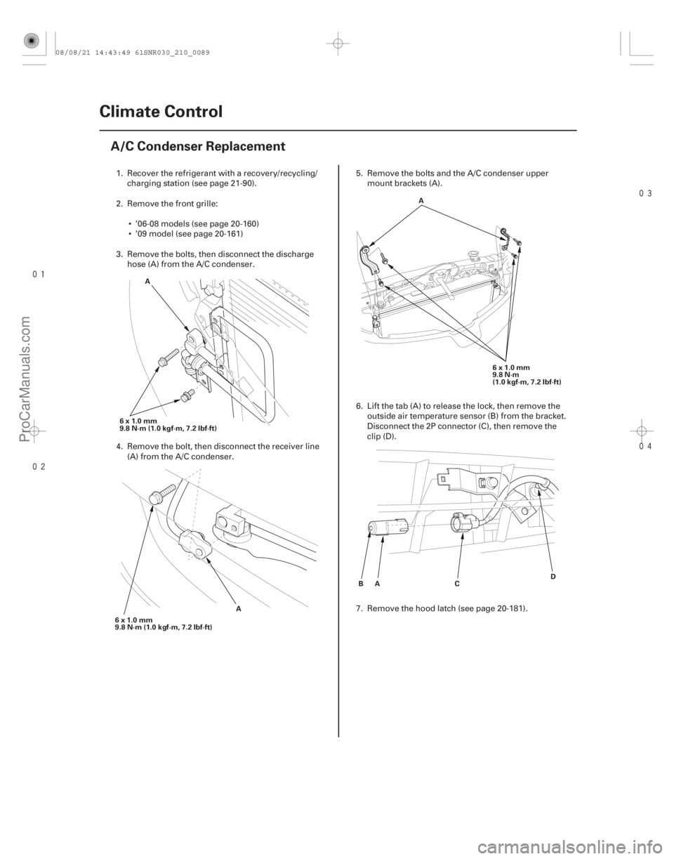
A/C Condenser Replacement
6x1.0mm
9.8 N·m (1.0 kgf·m, 7.2 lbf·ft)
A
6x1.0mm
9.8 N·m (1.0 kgf·m, 7.2 lbf·ft) A 6x1.0mm
9.8 N·m
(1.0 kgf·m, 7.2 lbf·ft)
A
A
B CD
1. Recover the refrigerant with a recovery/recycling/
charging station (see page 21-90).
2. Remove the front grille: ’06-08 models (see page 20-160)
’09 model (see page 20-161)
3. Remove the bolts, then disconnect the discharge hose (A) from the A/C condenser.
4. Remove the bolt, then disconnect the receiver line (A) from the A/C condenser. 5. Remove the bolts and the A/C condenser upper
mount brackets (A).
6. Lift the tab (A) to release the lock, then remove the outside air temperature sensor (B) from the bracket.
Disconnect the 2P connector (C), then remove the
clip (D).
7. Remove the hood latch (see page 20-181).
08/08/21 14:43:49 61SNR030_210_0089
ProCarManuals.com
DYNOMITE -2009-
Page 1976 of 2893
����
Special Tools Required
Leak Detector Usage Tips (Refer to the
Operator’s Manual for complete operating
instructions)
21-93
Refrigerant Leak Check
")
�(�#�'�����������
���
���������������
�"�����)����
Special Tools Required
Leak Detector Usage Tips (Refer to the
Operator’s Manual for complete operating
instructions)
21-93
Refrigerant Leak Check
Leak detector YGK-H-10PM
Leak detector HLD-100
Leak detector TIFZX-1, or commercially available
OPTIMAX Jr. A/C Leak Detection Kit (TRP124893)
These tools are available through the Honda Tool and
Equipment Program; call
888-424-6857
Air conditioning refrigerant or lubricant vapor can irritate your eyes, nose, or throat.
Be careful when connecting service equipment.
Do not breathe refrigerant or vapor.
NOTE: If accidental system discharge occurs, ventilate the work area before resuming service.
Additional health and safety information may be obtained from the refrigerant and lubricant
manufacturers.
Check the system for leaks using an R-134a refrigerant leak detector with an accuracy of 14 g
(0.5 oz) per year or better. Position the vehicle in a wind-free work area. This will
aid in detecting small leaks.
When using the leak detector for the first time, allow it to warm up for 2 minutes with the probe in a clean
atmosphere. This lets the temperature sensor in the
detector stabilize.
The calibration check should be done in the ‘‘Search 2’’ mode. Once that is done, the other check
modes do not need calibrating.
When leak checking through the HVAC module drain hose, avoid drawing water into the probe. Water can
damage the internal pump and sensor.
Avoid creasing the flexible probe extension. Creases can restrict air flow and give false readings.
Because the detector recalibrates itself for ambient gases, it may be necessary to move the detector
away from the leak to clear the sensor. Once the
sensor has cleared, recheck the suspected leak.
When removing the clear probe tip, be careful not to lose the flow ball.
R-134a is heavier than air; always check below and to the sides of all potential leak sources.
Halogen leak detectors are sensitive to chemicals: windshield washing solutions, solvents/cleaners, and
some vehicle adhesives. Keep these chemicals out of
the area when doing leak detection.
(cont’d)
08/08/21 14:44:53 61SNR030_210_0094
ProCarManuals.com
DYNOMITE -2009-
Page 1988 of 2893

Test results Related symptoms Probable causeRemedy
21-105
The suction pressure
is high, the discharge
pressure is low, and
there are particle
contaminants in the
refrigerant lines
The expansion valve
and/or the compressor
discharge hose are
contaminated with metal
flakes or desiccant
particles. The A/C compressor
is malfunctioning.
Replace the A/C compressor (see page
21-83). If the system is contaminated
with desiccant, replace the receiver/
dryer (see page 21-89).
The suction pressure
is high, the discharge
pressure is low, and
the pressures quickly
change when the A/C
disengages The discharge and
suction pressures
equalize soon after the
A/C compressor stops.
The A/C compressor
seal is faulty.
Replace the A/C compressor (see page
21-83).
Suction and
discharge pressures
are both low and
none of the
refrigerant lines are
cold There is no frost on the
expansion valve, and the
low-pressure liquid line is
not cold.
The A/C system has a
leak (very low
refrigerant charge).
Do the refrigerant leak check
(see page 21-93), repair any leaks, and
recharge the A/C system (see page
21-92).
Suction and
discharge pressures
are both low, and the
expansion valve or
the suction line is
abnormally cold The temperature
around the expansion
valve is too low
compared to the
temperature around
the receiver/dryer.
The low pressure
(suction) hose/line is
cooler than the
evaporator.The discharge hose/
line is clogged or
kinked, which is
restricting refrigerant
flow.
The suction hose/line
is clogged or kinked,
which is restricting
refrigerant flow.
Repair or replace the faulty A/C line
(see page 21-8).
Initially, the suction
and discharge
pressure are normal,
but both become
abnormally low
during operation During extended
operation, the air flow
from the vents decreases.
The evaporator is
freezing up.
Run the fan with A/C compressor off to
warm the evaporator, then test the
evaporator temperature sensor
(see page 21-70). If necessary, replace
the evaporator temperature sensor.
Suction and
discharge pressures
are both low and
there are abnormal
temperature changes
at the expansion
valve During extended
operation, warm air
comes out of the vents,
the suction pressure
decreases, and heavy
frost occurs on the low
pressure liquid line.
The low pressure liquid
line is cold at the
expansion valve, but
warm after the valve.
There is frost on the
expansion valve.The expansion valve
is stuck closed.
Replace the expansion valve
(see page 21-80), and the receiver/
dryer (see page 21-89).
Check the old expansion valve for
contamination. If contaminants are
found, replace the component that
caused the contamination.
(cont’d)
08/08/21 14:44:57 61SNR030_210_0106
ProCarManuals.com
DYNOMITE -2009-