Page 1395 of 2893

10x1.25mm
A
B
A
B
10x1.25mm
10x1.25mm
10x1.25mm
54 N·m
(5.5 kgf·m,
40 lbf·ft) 10x1.25mm
54 N")
�
��
�
������
����
Installation
17-72EPS Components
Steering Gearbox Removal and Installation (cont’d)
10x1.25mm
A
B
A
B
10x1.25mm
10x1.25mm
10x1.25mm
54 N·m
(5.5 kgf·m,
40 lbf·ft) 10x1.25mm
54 N·m
(5.5 kgf·m,
40 lbf·ft)
10x1.25mm
59 N·m
(6.0 kgf·m, 43 lbf·ft)
A
A
10x1.25mm
38 N·m
(3.9 kgf·m,
28 lbf·ft)FRONT
A BC
39. Remove the two 10 mm bolts from the right side of
the steering gearbox, then remove the gearbox
mounting bracket (A) and the mounting cushion (B).
40. Remove the four 10 mm flange bolts from the left side of the steering gearbox, then remove the
stiffener plates (A).
41. Remove the steering gearbox (B) from the front subframe. 1. Place the steering gearbox in position on the front
subframe.
2. Loosely install the stiffener plates (A) and the gearbox mounting bolts on the left side of the
steering gearbox.
3. Position the cutout (A) on the mounting cushion (B) as shown, and install it on the right side of the
steering gearbox securely.
4. Install the gearbox mounting bracket (C) over the mounting cushion, and loosely install the two
10 mm bolts.
5. Tighten the 10 mm bolts on both sides of the steering gearbox to the specified torque alternately
in two or more steps.
08/08/21 14:55:14 61SNR030_170_0073
ProCarManuals.com
DYNOMITE -2009-
Page 1396 of 2893

A BB
A
6. Install the pinion shaft grommet (A). Align the slotin the pinion shaft grommet with the lug portion (")
����
����� ����
����
17-73
A
B
D
C
B
A B
A
6x1.0mm
9.8 N·m
(1.0 kgf·m,
7.2 lbf·ft)
A BB
A
6. Install the pinion shaft grommet (A). Align the slotin the pinion shaft grommet with the lug portion (B)
on the torque sensor. The grommet must not have
a gap at the mating surface of the grommet and the
torque sensor.
7. Install the EPS motor connector A (2P), the EPS motor connector B (1P), torque sensor 4P connector
(C), the EPS motor angle sensor 6P connector (D)
on the right side of the gearbox mounting bracket. 8. Install the harness clips (A) to the harness clamp
bracket (B), then install the harness clamp bracket
to the front subframe.
9. Carefully raise the front subframe with the front subframe adaptor and the transmission jack or the
powertrain lift until the front subframe is in position,
then loosely install the new front subframe
mounting bolts.
NOTE: Be sure that the pinion shaft grommet is in
place securely. Check whether the pinion shaft
grommet is not turning up. Incorrect installation
can cause leakage of water, mud, and noise.
10. Align the front subframe reference marks (A) to the body (B), as noted during removal.
(cont’d)
08/08/21 14:55:15 61SNR030_170_0074
ProCarManuals.com
DYNOMITE -2009-
Page 1397 of 2893
����
�����
��
����
17-74EPS Components
Steering Gearbox Removal and Installation (cont’d)
A
14x1.5mm
103 N·m
(10.5 kgf·m,
75.9 lbf·ft)
A
14x1.5mm
103 N·m
(10.5 kgf·m,
75.9 lbf·ft) B
12x1.25mm
64 N·m
(6.5 kgf·m, 47 lbf·ft)
A
B A
6x1.0mm
12 N·m
(1.2 kgf·m,
8.7 lbf·ft)
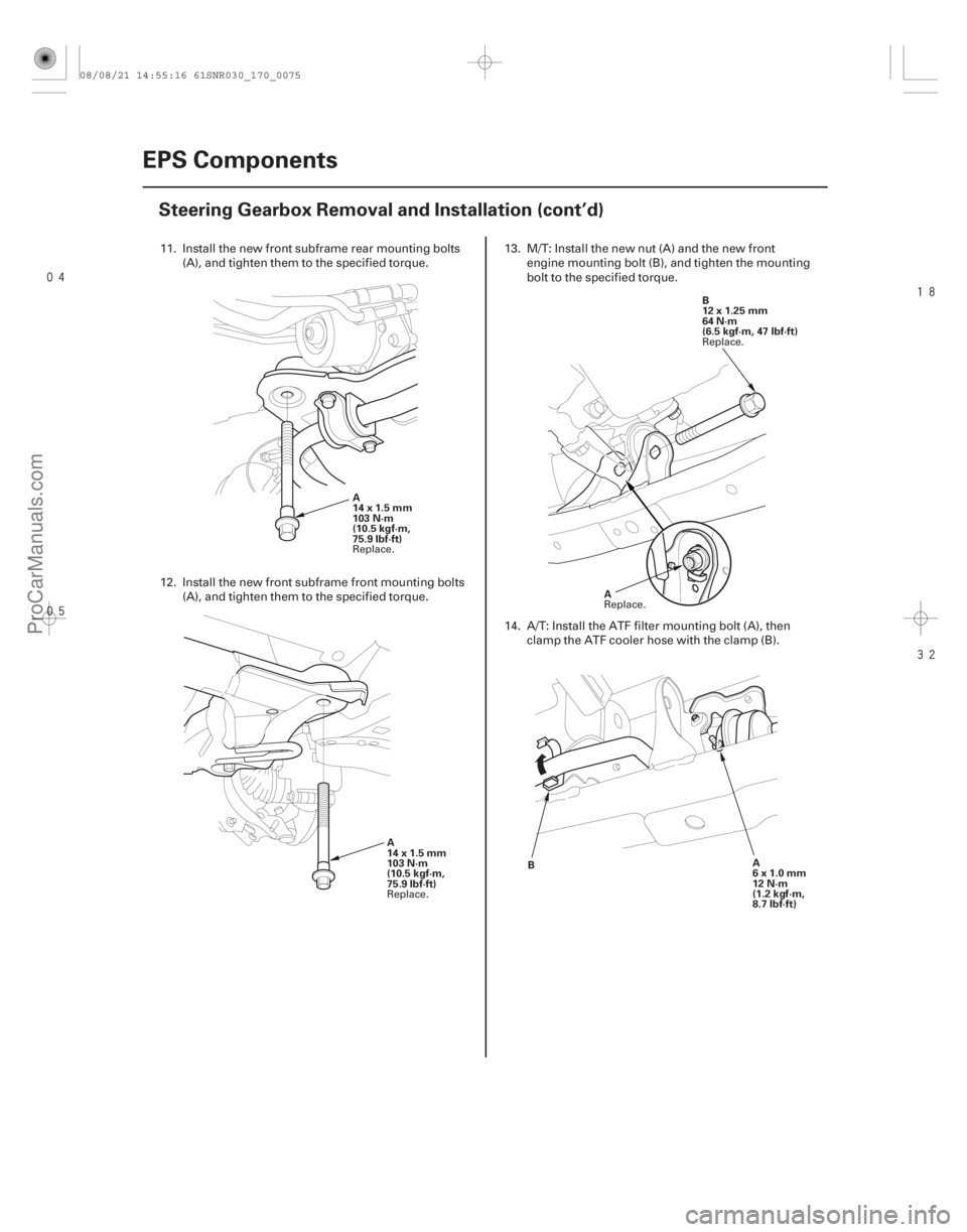
11. Install the new front subframe rear mounting bolts
(A), and tighten them to the specified torque.
12. Install the new front subframe front mounting bolts (A), and tighten them to the specified torque. 13. M/T: Install the new nut (A) and the new front
engine mounting bolt (B), and tighten the mounting
bolt to the specified torque.
14. A/T: Install the ATF filter mounting bolt (A), then clamp the ATF cooler hose with the clamp (B).
Replace.
Replace. Replace.
Replace.
08/08/21 14:55:16 61SNR030_170_0075
ProCarManuals.com
DYNOMITE -2009-
Page 1399 of 2893

A
B
C
12x1.25mm
59 N·m
(6.0 kgf·m, 43 lbf·ft)
D
12x1.25mm
59 N·m
(6.0 kgf·m, 43 lbf·ft) B
A
E
12x1.")
����
���������
����
17-76EPS Components
Steering Gearbox Removal and Installation (cont’d)
A
B
C
12x1.25mm
59 N·m
(6.0 kgf·m, 43 lbf·ft)
D
12x1.25mm
59 N·m
(6.0 kgf·m, 43 lbf·ft) B
A
E
12x1.25mm
59 N·m
(6.0 kgf·m,
43 lbf·ft) D
C
AB
B
12x1.25mm
54 N·m
(5.5 kgf·m,
40 lbf·ft)
A D
E
C
20. Install the exhaust hanger (A) to the three way
catalytic converter (TWC) (B).
21. Connect the lower arm (A) to the lower ball joint (B).
22. Install a new flange bolt and the new self-locking nuts. After lightly tightening all three fasteners,
tighten them to the specified torque in the
following order; the self-locking nut on the front (C),
the self-locking nut on the rear (D), then the flange
bolt (E). 23. Remove the vinyl tape, then connect the EPS motor
connector A (2P), the EPS motor connector B (1P),
torque sensor 4P connector (C), the EPS motor
angle sensor 6P connector (D) to the steering
gearbox. Make sure to push these connectors until
you hear a click so that the connectors are secured.
24. Install the front splash shield (see page 20-172).
25. Wipe off any grease contamination from the ball joint tapered section and the threads. Reconnect
the tie-rod ends (A) to the steering knuckles. Install
the 12 mm nut (B) and tighten it.
26. Install the new cotter pin (C), and bend it as shown (D) or (E).
27. Install the front wheel, then set the wheels in the straight ahead position.
NOTE: Before installing the wheel, clean the mating
surfaces between the brake disc and inside of the
wheel.
Replace.
Replace.
Replace. Replace.
08/08/21 14:55:18 61SNR030_170_0077
ProCarManuals.com
DYNOMITE -2009-
Page 1401 of 2893

34. Install the steering wheel (see page 17-8).
35. With the tires raised off the ground (vehicle on a
li")
SymptomProbable cause
17-78EPS Components
Steering Gearbox Removal and Installation (cont’d)
34. Install the steering wheel (see page 17-8).
35. With the tires raised off the ground (vehicle on a
lift), check for the following symptoms by turning
the steering wheel fully to the right and left several
times.
Rubbing sound
coming from the
lower steering
column area. Steering column joint
is contacting the cover.
Grating sound from
the lower steering
column area, or a
rough feeling during
steering. Poor engagement of
the pinion shaft
serrations.
Noise from around
the steering wheel
during steering. Poor engagement of
the SRS cable reel with
the steering wheel, or a
damaged cable reel.
36. Install the air cleaner housing (see page 11- 345).
37. Install the under cowl panel and cowl cover (see page 20-163). 38. Do the battery terminal reconnection procedure
(see page 22-68), and do these tasks:
Turn the ignition switch to ON (II) and check that the SRS indicator comes on for about 6 seconds
and then goes off.
Make sure the horn and turn signal switches work properly.
Make sure the steering wheel switches work properly.
39. After installation, do the following checks: Check the steering wheel spoke angle. If steeringspoke angles to the right and left are not equal
(steering wheel and rack are not centered),
correct the engagement of the joint/pinion shaft
splines.
Set the steering column to the center tilt position, and to the center telescopic position, then check
the wheel alignment and adjust (see page 18-5).
Make sure the steering wheel spokes are centered.
Start the engine, and let it idle. Turn the steering wheel from lock-to-lock several times. Check that
the EPS indicator does not come on.
Do the memorizing for the torque sensor neutral position (see page 17-22).
08/08/21 14:55:18 61SNR030_170_0079
ProCarManuals.com
DYNOMITE -2009-
Page 1402 of 2893
����
�(�#�'�����������
���
�����������
����� �����)����
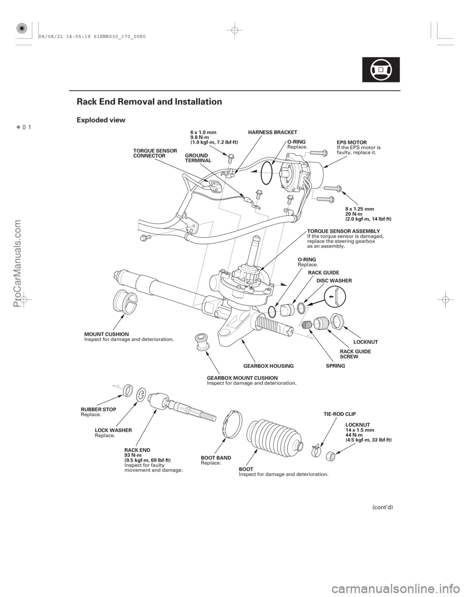
Exploded view
17-79
Rack End Removal and Installation
O-RING
TORQUE SENSOR
CONNECTOR
8x1.25mm
20 N·m
(2.0 kgf·m, 14 lbf·ft)
EPS MOTOR
6x1.0mm
9.8 N·m
(1.0 kgf·m, 7.2 lbf·ft)
LOCKNUT
RACK GUIDE
DISC WASHER
O-RING
SPRING
GEARBOX MOUNT CUSHION GEARBOX HOUSING
MOUNT CUSHION
TIE-ROD CLIPLOCKNUT
14 x 1.5 mm
44 N·m
(4.5 kgf·m, 33 lbf·ft)
BOOT
BOOT BAND
RACK END
93 N·m
(9.5 kgf·m, 69 lbf·ft)
LOCK WASHER
RUBBER STOP GROUND
TERMINAL
TORQUE SENSOR ASSEMBLY
RACK GUIDE
SCREW
HARNESS BRACKET
(cont’d)
Replace.
If the EPS motor is
faulty, replace it.
Replace.
Inspect for damage and deterioration.
Inspect for damage and deterioration.
Inspect for damage and deterioration.
Replace.
Inspect for faulty
movement and damage.
Replace.
Replace. If the torque sensor is damaged,
replace the steering gearbox
as an assembly.
08/08/21 14:55:19 61SNR030_170_0080
ProCarManuals.com
DYNOMITE -2009-
Page 1403 of 2893
��������
����
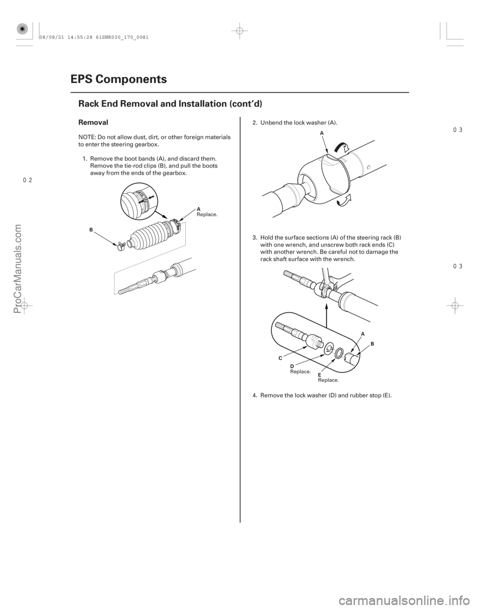
Removal
17-80EPS Components
Rack End Removal and Installation (cont’d)
B
A A
E
D A
B
C
NOTE: Do not allow dust, dirt, or other foreign materials
to enter the steering gearbox. 1. Remove the boot bands (A), and discard them. Remove the tie-rod clips (B), and pull the boots
away from the ends of the gearbox. 2. Unbend the lock washer (A).
3. Hold the surface sections (A) of the steering rack (B)
with one wrench, and unscrew both rack ends (C)
with another wrench. Be careful not to damage the
rack shaft surface with the wrench.
4. Remove the lock washer (D) and rubber stop (E).
Replace.
Replace.
Replace.
08/08/21 14:55:28 61SNR030_170_0081
ProCarManuals.com
DYNOMITE -2009-
Page 1405 of 2893
��������
����
17-82EPS Components
Rack End Removal and Installation (cont’d)
A
B
C
D A
B
BA4mm
(0.16 in.)
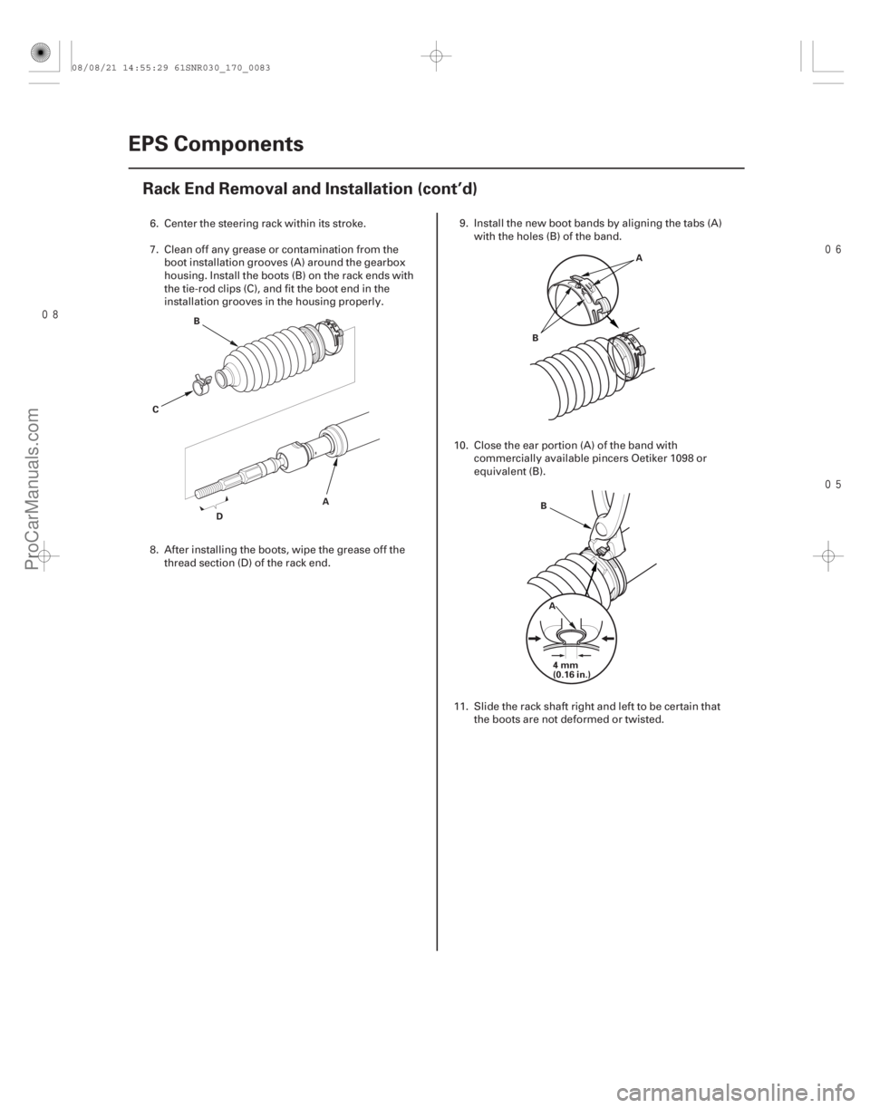
6. Center the steering rack within its stroke.
7. Clean off any grease or contamination from the boot installation grooves (A) around the gearbox
housing. Install the boots (B) on the rack ends with
the tie-rod clips (C), and fit the boot end in the
installation grooves in the housing properly.
8. After installing the boots, wipe the grease off the
thread section (D) of the rack end. 9. Install the new boot bands by aligning the tabs (A)
with the holes (B) of the band.
10. Close the ear portion (A) of the band with commercially available pincers Oetiker 1098 or
equivalent (B).
11. Slide the rack shaft right and left to be certain that the boots are not deformed or twisted.
08/08/21 14:55:29 61SNR030_170_0083
ProCarManuals.com
DYNOMITE -2009-