Page 1486 of 2893
�����(�#����������������
�����
�����������������)����
�µ
�µ �µ
�µ
�µ
�µ
�µ
�µ
TPMS indicator does not come on, and no
DTCs are stored TPMS indica")
�(�#�'���������������
�����
�����������������)�����(�#�'���������������
�����
�����������������)����
�µ
�µ �µ
�µ
�µ
�µ
�µ
�µ
TPMS indicator does not come on, and no
DTCs are stored TPMS indicator does not go off, and no DTCs
are stored
YES
NO YES
NO
YES
NO
YES
NO
18-7318-73
1. Turn the ignition switch to LOCK (0).
2. Disconnect the TPMS control unit 20P connector.
3. Turn the ignition switch to ON (II).
4. Check the TPMS indicator for several sec
onds
when the ignition switch is turned ON (II).
Check for loose terminals and poor
connections at the TPMS control unit. If necessary,
substitute a known-good TPMS control unit
(see page 18-75), and recheck.
Do the troubleshooting for the gauge control
module (see page 22- 241). If necessary, substitute a
known-good gauge control module (tach) (see page
22-277), and recheck. NOTE: Check for gauge DTCs with the HDS (see page
22-6). If gauge DTCs are stored, troubleshoot those
DTCs first.
1. Turn the ignition switch to ON (II).
2. Check the TPMS indicator for several sec onds
when the ignition switch is turned ON (II).
The system is OK at this time.
Go to step 3.
3. Turn the ignition switch to LOCK (0).
4. Check the No. 7 (7.5 A) fuse in the under-dash fuse/ relay box.
Replace the No. 7 (7.5 A) fuse, and recheck. If
the fuse blows again, check for a short to body
ground in the wire between the TPMS control unit
and the No. 7 (7.5 A) fuse in the under-dash fuse/
relay box.
Reinstall the checked fuse, then go to step 5.
5. Check the No. 10 (7.5 A) fuse in the under-dash fuse/relay box.
Replace the No. 10 (7.5 A) fuse, and recheck.
If the fuse blows again, check for a short to body
ground in the wire between the TPMS control unit
and the No. 10 (7.5 A) fuse in the under-dash fuse/
relay box.
Reinstall the checked fuse, then go to step 6.
6. Disconnect the TPMS control unit 20P connector.
(cont’d)
Di d t he i nd i cat or come on? Di d t he i nd i cat or come on, and t hen go of f ?
Isthefuseblown?
Isthefuseblown?
08/08/21 14:59:00 61SNR030_180_0073
ProCarManuals.com
DYNOMITE -2009-
Page 1487 of 2893

TPMS CONTROL UNIT 20P CONNECTOR
B(BLU)
TPMS CONTROL UNIT 20P CONNECTOR IG1 (BRN) TPMS CONTRO")
����
��������
�´
�µ
�µ
�µ
�µ �µ
�µ
YES
NO
YES
NO YES
NO
18-74TPMS
Symptom Troubleshooting (cont’d)
TPMS CONTROL UNIT 20P CONNECTOR
B(BLU)
TPMS CONTROL UNIT 20P CONNECTOR IG1 (BRN) TPMS CONTROL UNIT 20P CONNECTOR
GND (BLK)
7. Measure the voltage between body ground and TPMS control unit 20P connector terminal No. 10.
Go to step 8.
Repair open in the wire between the TPMS
control unit and the No. 7 (7.5 A) fuse in the under-
dash fuse/relay box.
8. Turn the ignition switch to ON (II).
9. Measure the voltage between body ground and TPMS control unit 20P connector terminal No. 8.
Go to step 10.
Repair open in the wire between the TPMS
control unit and the No. 10 (7.5 A) fuse in the under-
dash fuse/relay box. 10. Turn the ignition switch to LOCK (0).
11. Reconnect the TPMS control unit 20P connector.
12. Turn the ignition switch to ON (II).
13. Measure the voltage between body ground and
TPMS control unit 20P connector terminal No. 3.
Repair open or high resistance in the wire
between the TPMS control unit and body ground
(G504).
Do the troubleshooting for the gauge control
module (see page 22-241). If the gauge control
module (tach) is OK, check for loose terminals and
poor connections at the TPMS control unit. If
necessary, substitute a known-good TPMS control
unit (see page 18-75), and recheck.
Wire side of female terminals
Wire side of female terminals Wire side of female terminals
Is there battery voltage?
Is there battery voltage? Is t her e 0.1 V or mor e?
08/08/21 14:59:01 61SNR030_180_0074
ProCarManuals.com
DYNOMITE -2009-
Page 1488 of 2893
����
18-75
TPMS Control Unit Replacement
A
B
C
D
C B
6x1.0mm
9.8 N·m (1.0 kgf·m, 7.2 lbf·ft)
NOTE: Make sure the TPMS control unit mounting
brac")
����
�(�#�'���������������
�����
���������
� �����)����
18-75
TPMS Control Unit Replacement
A
B
C
D
C B
6x1.0mm
9.8 N·m (1.0 kgf·m, 7.2 lbf·ft)
NOTE: Make sure the TPMS control unit mounting
bracket is not bent or twisted as this may affect its
communication with the tire pressure sensors.
1. Turn the ignition switch to LOCK (0).
2. Remove the driver’s dashboard undercover (see page 20-103).
3. Disconnect the TPMS control unit connector (A).
4. Remove the TPMS control unit (B) from the bracket (C).
NOTE: To disconnect the TPMS control unit from its
bracket, insert a small flat-tipped screwdriver
between the TPMS control unit and the bracket
shown in (D) to release the hook, then slide out the
TPMS unit.
5. Replace the bracket if necessary. 6. Install the new TPMS control unit in the reverse
order of removal.
NOTE: Make sure the TPMS control unit is properly
installed. You will hear a click when the TPMS
control unit is securely mounted on the bracket.
7. Connect the HDS, and memorize the tire pressure sensor IDs using the TPMS sensor initializer tool
(see page 18-52).
08/08/21 14:59:01 61SNR030_180_0075
ProCarManuals.com
DYNOMITE -2009-
Page 1489 of 2893
����
Removal
18-76 TPMS
Tire Pressure Sensor Replacement
A
C
B 90 °
OUTSIDE A
B
C
AB
C
1. Raise the vehicle, and support it with safety sta")
���
����
����
�(�#�'���������������
�����
����������� �����)����
Removal
18-76 TPMS
Tire Pressure Sensor Replacement
A
C
B 90 °
OUTSIDE A
B
C
AB
C
1. Raise the vehicle, and support it with safety stands in the proper locations (see page 1-11).
2. Remove the wheel with the faulty sensor.
3. Remove the tire valve stem cap and the valve stem core, to deflate the tire.
4. Remove any balance weights, and then break the bead loose from the wheel with a commercially
available tire changer (A).
Note these items to avoid damaging the tire
pressure sensor: Do the outside of the wheel first.
Position the wheel as shown so the valve stem (B) is 90 degrees from the bead
breaker (C) as shown.
Do not position the bead breaker of the tire changer too close to the rim. 5. Position the wheel so the tire machine (A) and tire
iron (B) are next to the valve stem (C), and will
move away from it when the machine starts. Then
remove the tire from the wheel.
6. Remove the valve stem nut (A) and the washer (B), then remove the tire pressure sensor with the valve
stem (C) from the wheel.
NOTE: Check the nut and the washer, If they have
deterioration or damage, replace then with new
ones during reassembly.
08/08/21 14:59:02 61SNR030_180_0076
ProCarManuals.com
DYNOMITE -2009-
Page 1490 of 2893
��������
Installation
18-77
B
A A
A A
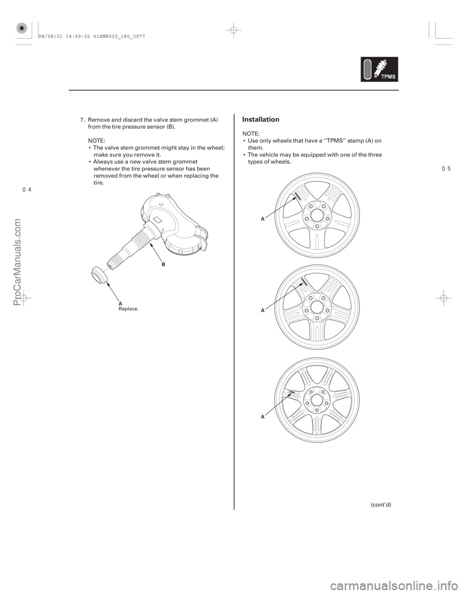
7. Remove and discard the valve stem grommet (A) from the tire pressure sensor (B).
NOTE: The valve stem grommet might stay in the wheel; make sure you remove it.
Always use a new valve stem grommet whenever the tire pressure sensor has been
removed from the wheel or when replacing the
tire. NOTE:
Use only wheels that have a ‘‘TPMS’’ stamp (A) on them.
The vehicle may be equipped with one of the three types of wheels.
(cont’d)
Replace.
08/08/21 14:59:02 61SNR030_180_0077
ProCarManuals.com
DYNOMITE -2009-
Page 1491 of 2893

A
BC
D
4N·m
(0.4 kgf·m, 3 lbf·ft)
F
E
OUT SIDE
WHEEL CENTER F
E EA
B
C
1. Before installing the tire pressure sensor, clean the
mating")
��������
18-78TPMS
Tire Pressure Sensor Replacement (cont’d)
A
BC
D
4N·m
(0.4 kgf·m, 3 lbf·ft)
F
E
OUT SIDE
WHEEL CENTER F
E EA
B
C
1. Before installing the tire pressure sensor, clean the
mating surfaces on the sensor and the wheel.
2. Install the tire pressure sensor (A) and the washer (B) to the wheel (C), and tighten the valve stem nut
(D) finger tight. Make sure the pressure sensor is
restingonthewheel.
NOTE: Install the tire pressure sensor so that
sensor housing surface (E) should not exceed
protrusion (F) of wheel to prevent the sensor
housing from being caught on the bead of the tire
when assembling the tire.
3. Tighten the valve stem nut to the specified torque while holding the tire pressure sensor.
NOTE: Do not use air or electric impact tools to tighten a valve stem nut.
Do not twist the tire pressure sensor to adjust its position with the wheel, as this will damage or
deform the valve stem grommet. 4. Lube the tire bead sparingly with a paste-type tire
mounting lubricant, and position the wheel so the
tire machine (A) and tire iron (B) are next to the
valve stem (C) and will move away from it when
the machine starts. Then install the tire onto the
wheel.
5. With a dry air source, inflate the tire to 300 kPa (3.1 kgf/cm , 44 psi) to seat the tire bead to the rim,
then adjust the tire pressure (see page 18-5), then
install the valve stem cap.
NOTE: Make sure the tire bead is seated on both
sides of the rim uniformly.
6. Check and adjust the wheel balance, then install the wheels on the vehicle.
7. Remove the jack stands, and lower the vehicle. Torque the wheel nuts to specification.
8. Connect the HDS, and memorize the tire pressure sensor IDs using the TPMS sensor initializer tool
(see page 18-52).
2
08/08/21 14:59:02 61SNR030_180_0078
ProCarManuals.com
DYNOMITE -2009-
Page 1999 of 2893
�����
22-9
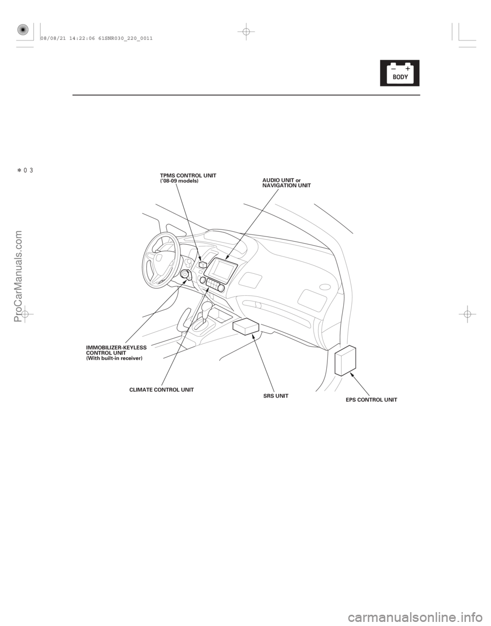
SRS UNIT
CLIMATE CONTROL UNIT
IMMOBILIZER-KEYLESS
CONTROL UNIT
(With built-in receiver)
EPS CONTROL UNIT
AUDIO UNIT or
NAVIGATION UNIT
TPMS CONTROL UNIT
(’08-09 models)
08/08/21 14:22:06 61SNR030_220_0011
ProCarManuals.com
DYNOMITE -2009-
Page 2008 of 2893
 or Circuit(s) Protected
22-62Power Distribution
Fuse to Components Index (cont’d)
1 7.5 A Power")
�•�•�•
�•�•�•�´
�´
�•�•�•
Under-dash Fuse/Relay Box
Fuse
Number Amps
Component(s) or Circuit(s) Protected
22-62Power Distribution
Fuse to Components Index (cont’d)
1 7.5 A Power mirror switch light
2 15 A ECM/PCM, Fuel pump (via PGM-FI main relay 2), Immobilizer-keyless control unit
3 10 A Alternator, CMP sensor A, ECM/PCM (via brake pedal position switch), ELD, EVAP canister purge valve, MAF
sensor/IAT sensor, Reverse lockout solenoid , Secondary HO2S (sensor 2)
4 7.5 A ABS modulator-control unit , EPS control unit, VSA modulator-control unit , Yaw rate-lateral acceleration sensor
5 15 A Seat heaters (via seat heater relays)
6 20 A Fog light relay, Fog lights (via fog light relay)
7 Not used
8 Not used
9 7.5 A ODS unit, Passenger’s airbag cutoff indicator, SRS unit
10 7.5 A Back-up light (M/T), Gauge control module (speedo), Gauge control module (tach), MICU, Shift lock solenoid (A/T), TPMS control unit
11 10 A SRS unit
12 10 A Right headlight (high beam)
13 10 A Left headlight (high beam)
14 7.5 A Audio unit light , Climate control unit light, Dash lights brightness controller and odometer select/reset switch light, Driver’s footwell light , Driver’s seat heater switch light, Glove box light, Hazard warning switch light,
Moonroof switch light, Navigation unit , Park pin switch light (A/T), Passenger’s airbag cutoff indicator light,
Passenger’s footwell light , Passenger’s seat heater switch light, Steering wheel switches light (via cable reel),
VSA OFF switch light
15 7.5 A Parking lights, Taillights, License plate lights, Side marker lights
16 10 A Right headlight (low beam) 15 A Right HID unit
17 10 A Left headlight (low beam) 15 A Left HID unit
18 20 A MICU ( B H/L HI)
19 15 A MICU ( B SMALL LT)
20 Not used
1: ’06-07 Touring and Premium models
2: ’07 TYPE S and ’08-09 models
3: ’08-09 models
4: TYPE S model
5: With HID
6: Without HID
7: TYPE S and ’08 Premium and ’09 models
8: Without navigation system
9: With navigation system
4
1 2
2
7
3
8 49
4
6
5
6
5
08/08/21 14:24:03 61SNR030_220_0064
ProCarManuals.com
DYNOMITE -2009-