Page 1470 of 2893
�•�•�•
�´
���
�(�#�'���������������
�����
�����������������)����
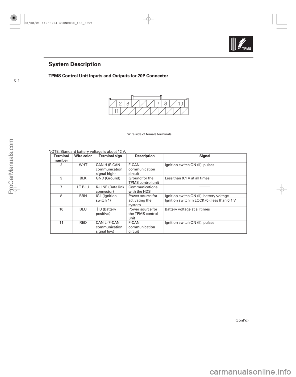
TPMS Control Unit Inputs and Outputs for 20P Connector
Terminalnumber Wire color Terminal sign Description Signal
18-57
System Description
NOTE: Standard battery voltage is about 12 V.
2 WHT CAN H (F-CAN communication
signal high)F-CAN
communication
circuit Ignition switch ON (II): pulses
3 BLK GND (Ground) Ground for the TPMS control unitLess than 0.1 V at all times
7 LT BLU K-LINE (Data link connector)Communications
with the HDS
8 BRN IG1 (Ignition switch 1)Power source for
activating the
system Ignition switch ON (II): battery voltage
Ignition switch in LOCK (0): less than 0.1 V
10 BLU B (Battery positive)Power source for
the TPMS control
unit Battery voltage at all times
11 RED CAN L (F-CAN communication
signal low)F-CAN
communication
circuit Ignition switch ON (II): pulses
(cont’d)
Wire side of female terminals
08/08/21 14:58:24 61SNR030_180_0057
ProCarManuals.com
DYNOMITE -2009-
Page 1471 of 2893

Vehicle
Indicators (LED)
Gauge Control Module (Tach)
Communication
via F-CAN
Control Unit
(with radio
frequency")
����
System Structure
Control unit
Indicators
18-58TPMS
System Description (cont’d)
Vehicle
Indicators (LED)
Gauge Control Module (Tach)
Communication
via F-CAN
Control Unit
(with radio
frequency antenna)
Tire Pressure Sensor
(sensor-transmitter
with acceleration sensor) Wheel
(TPMS type)
Tire Pressure Sensor
(sensor-transmitter
with acceleration sensor)
Tire Pressure Sensor
(sensor-transmitter
with acceleration sensor)
Tire Pressure Sensor
(sensor-transmitter
with acceleration sensor)
Wheel
(TPMS type)
Wheel
(TPMS type) Wheel
(TPMS type)
Once the vehicle speed exceeds 45 km/h (28 mph), the TPMS control unit monitors all four tire pressure sensors and
the system function. If it detects low pressure in a tire, it alerts the driver by turning on the low tire pressure indicator.
If it detects a problem in the system, it turns on the TPMS indicator.
Mounted inside of the dash, the TPMS control unit receives wireless pressure sensor ID signals
every time the vehicle
speeds exceeds 45 km/h (28 mph). It also receives wireless signals from the transmitters for tire pressure and the
sensor condition, and it continuously monitors and controls the system. The TPMS control unit cannot directly
determine the position (location) of a tire pressure sensor(s) on the vehicle since it is a wireless system. TPMS sensor
locations will change during scheduled vehicle maintenance (tire rotation).
NOTE: To determine the actual location of each TPMS wheel sensor on the vehicle, do the tire pressure sensor
location procedure (see page 18-53). Once the tire pressure sensor locations are identified, write the sensor ID on the
side wall of the tire with a tire crayon to eliminate confusion.
Two indicators are in the gauge control module (tach): The low tire pressure indicator comes on when any tire
pressure is low, and the TPMS indicator that comes on only if there’s a problem with the system.
The low tire pressure indicator alerts the driver that a tire(s) pressure is low, but does not specify the tire(s) location.
08/08/21 14:58:24 61SNR030_180_0058
ProCarManuals.com
DYNOMITE -2009-
Page 1472 of 2893

����Tire pressure sensor
Wheels
18-59
A
B
C
B
C
A B
C A
Each sensor is an integrated unit made up of the tire valve stem, a tire pressure sensor, and a transmitter. The unit is
attached to the inside of the wheel, around the valve stem. The sensor transmits the internal tire information to the
control unit once every 60 seconds when the vehicle speed exceeds 45 km/h (28 mph). When the TPMS control unit
receives a tire pressure signal that is less than 175 kPa (1.8 kgf/cm , 25 psi) with 16 inch wheels, or 183 kPa (1.9 kgf/cm ,
27 psi) with 17 inch wheels, the TPMS control unit then turns on the low tire pressure indicator. When that tire’s
pressure is increased to more than 200 kPa (2.0 kgf/cm , 29 psi) with 16 inch wheels, or 210 kPa (2.1 kgf/cm , 30 psi)
with 17 inch wheels, and the vehicle is driven above 45 km/h (28 mph) the transmitter sends the tire pressure signal to
the control unit, and then the control unit turns the indicator off.
NOTE: Do not mix the TPMS tire pressure sensors or wheels with other TPMS types. Be sure to use the correct type
sensors and wheels for this system.
Sensor are active:
When the wheel rotates over 45 km/h (28 mph), the sensor detects the momentum, switches the sensor to the normal function mode.
The LF (low frequency) signal of the TPMS tool makes the sensor active even t hough the vehicle is stopped. The tire
pressure sensor goes into sleep mode when the acceleration sensor detects the wheel is stationary for 5 minutes or
more continuously.
The TPMS will not work unless TPMS type wheels are installed on the vehicle. There are three different types of
wheels used. The original equipment wheels have a ‘‘TPMS’’ mark (A) on them and are counterweighted (B) the
opposite of the tire pressure sensor (C), and counterbalance the weight of the sensor.
(cont’d)
22
2 2
08/08/21 14:58:25 61SNR030_180_0059
ProCarManuals.com
DYNOMITE -2009-
Page 1473 of 2893

Control Unit
(With Radio Frequecy Antenna)
Tire Pressure Sensor
(Sensor-transmitter with acceleration sensor)
When the vehicle is tr")
����
System Communication
18-60TPMS
System Description (cont’d)
Control Unit
(With Radio Frequecy Antenna)
Tire Pressure Sensor
(Sensor-transmitter with acceleration sensor)
When the vehicle is traveling more than 45 km/h (28 mph), an RF (radio frequency) band wave signal is transmitted
from each tire pressure sensor to the control unit.
When the wheels rotate, and the tire pressure sensors momentum is detected, switching them from sleep mode to normal function (awake) mode. After the vehicle is stationary for 5 minutes, the sensors switch from normal
function mode back to sleep mode to extend their battery life.
Each tire pressure sensor has its own ID to prevent jamming by similar systems on other vehicles. After memorizing all the sensor IDs, the control unit recognizes only those specific signals.
An ID cannot be memorized automatically. The control unit knows which ID belongs to each tire pressure sensor. This recurring ID confirmation prevents any confusion in the system as a result of normal tire rotation.
NOTE: Be careful not to bend the brackets on the TPMS control unit: Misalignment of the control unit could interfere
with sending and receiving signals.
08/08/21 14:58:25 61SNR030_180_0060
ProCarManuals.com
DYNOMITE -2009-
Page 1474 of 2893
���
�(�#�'���������������
�����
�����������������)����
�´
18-61
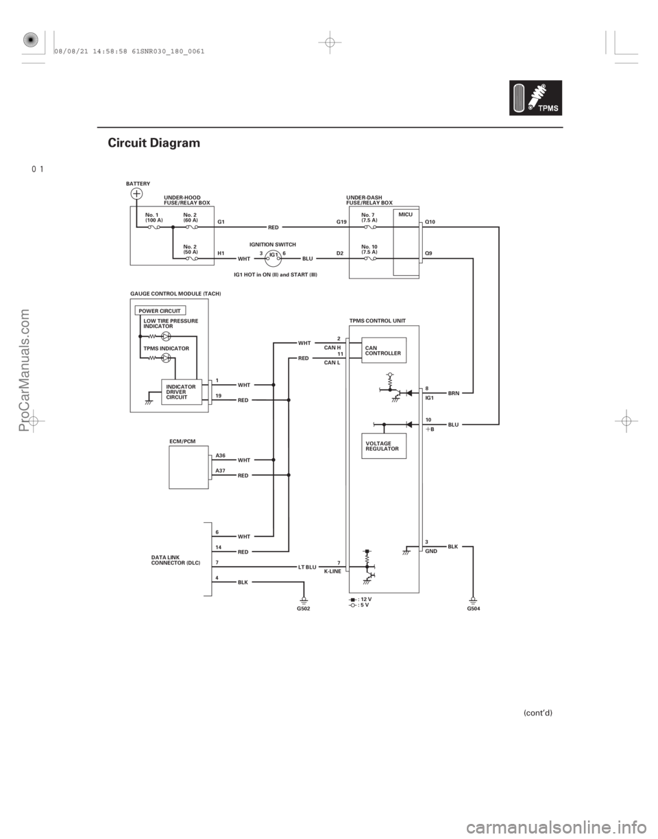
Circuit Diagram
BATTERYUNDER-HOOD
FUSE/RELAY BOX
G1
H1WHT 36
IGNITION SWITCH
No. 10
(7.5 A)
No. 2
(60 A)
No. 2
(50 A)
No. 1
(100 A)
No. 7
(7.5 A)
UNDER-DASH
FUSE/RELAY BOX
G19
D2
TPMS INDICATOR ECM/PCM WHT
RED
WHT
RED
BLK TPMS CONTROL UNIT
CAN
CONTROLLER
RED WHT RED WHT
VOLTAGE
REGULATOR8
10 IG1
B BRN
3
GND BLK
G502 G504 K-LINE
:12V
:5V
CAN H
CAN L
IG1
POWER CIRCUIT
INDICATOR
DRIVER
CIRCUIT IG1 HOT in ON (II) and START (III)
DATA LINK
CONNECTOR (DLC) LT BLUBLU
RED
BLU
2
11
LOW TIRE PRESSURE
INDICATOR
GAUGE CONTROL MODULE (TACH)
1
A36
A37 19
6
14 7
4 7Q10
Q9
MICU
(cont’d)
08/08/21 14:58:58 61SNR030_180_0061
ProCarManuals.com
DYNOMITE -2009-
Page 1475 of 2893
����
18-62TPMS
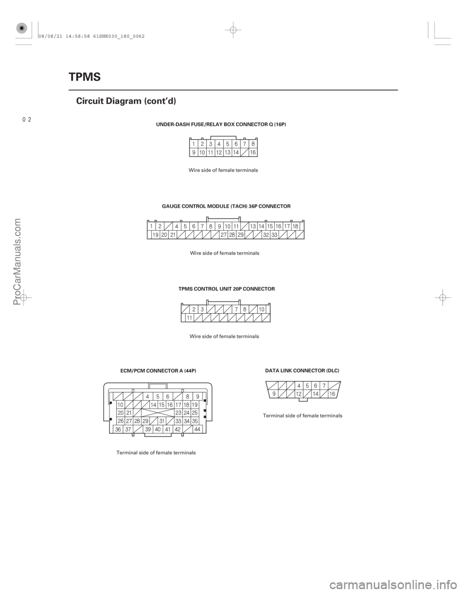
Circuit Diagram (cont’d)
DATA LINK CONNECTOR (DLC)
TPMS CONTROL UNIT 20P CONNECTOR
UNDER-DASH FUSE/RELAY BOX CONNECTOR Q (16P)
ECM/PCM CONNECTOR A (44P) GAUGE CONTROL MODULE (TACH) 36P CONNECTOR
Wire side of female terminals
Terminal side of female terminals Wire side of female terminals
Wire side of female terminals
Terminal side of female terminals
08/08/21 14:58:58 61SNR030_180_0062
ProCarManuals.com
DYNOMITE -2009-
Page 1476 of 2893
����
�µ
�µ�µ �µ
�µ
�µ
DTC 11, 13, 15, 17:
YES
NO DTC Tire Pressure Sensor Number
YES
NO
YES
NO
18-63
DTC Troubleshooting
Tire Low Air Pressure
NOTE:")
�(�#�'��������� ���������������
�
�
���������)����
�µ
�µ�µ �µ
�µ
�µ
DTC 11, 13, 15, 17:
YES
NO DTC Tire Pressure Sensor Number
YES
NO
YES
NO
18-63
DTC Troubleshooting
Tire Low Air Pressure
NOTE: If low tire pressure is detected, the control unit
sets one or more of these DTCs, and turns on the low
tire pressure indicator. If the low tire pressure indicator
comes on because of a low tire pressure, and the client
corrects it before bringing the vehicle in, the DTCs will
be stored, but the indicator turns off. 1. Turn the ignition switch to LOCK (0).
2. Make sure the tires are inflated to the specified tire pressure listed on the doorjamb sticker.
3. Test-drive the vehicle at 45 km/h (28 mph) or more for at least 1 minute.
The system is OK at this time. Check for and
repair the cause of air loss.
Go to step 4.
4. Check for DTCs with the HDS. 5. Note the tire pressure sensor(s) number by the
indicated DTC.
11 No. 1
13 No. 2
15 No. 3
17 No. 4
6. Do the tire pressure sensor location procedure to determine the affected tire location and relate it to
the tire pressure sensor number (see page 18-53).
7. Check the TIRE 1, TIRE 2, TIRE 3, or TIRE 4 AIR PRESSURE in the TPMS DATA LIST with the HDS,
and compare it with the actual measured tire
pressure.
Go to step 8.
Replace the appropriate tire pressure sensor
(see page 18-76).
8. Clear the DTC with the HDS.
9. Test-drive the vehicle at 45 km/h (28 mph) or more for at least 1 minute.
10. Check for DTCs with the HDS.
Replace the TPMS control unit (see page
18-75).
If any other DTCs are indicated, troubleshoot
the appropriate DTC. If no DTCs are indicated, the
system is OK at this time.
Does the low tire pressure indicator go of f ? Is the indicated tire pressure on the HDS within40 k Pa ( 0.4 k gf / cm , 6 psi ) of t he act ual t i r epr essur e?
I s DT C 11, 13, 15 , or 17 i nd i cat ed ?
2
08/08/21 14:58:58 61SNR030_180_0063
ProCarManuals.com
DYNOMITE -2009-
Page 1477 of 2893
����
�µ
�µ �µ
�µ
�µ
�µ
DTC 21, 22, 23, 24:
YES
NO
DTC Tire Pressure Sensor Number YES
NO
YES
NO
18-64TPMS
DTC Troubleshooting (cont’d)
Tire Pressu")
�(�#�'��������� ���������������
���
���������)����
�µ
�µ �µ
�µ
�µ
�µ
DTC 21, 22, 23, 24:
YES
NO
DTC Tire Pressure Sensor Number YES
NO
YES
NO
18-64TPMS
DTC Troubleshooting (cont’d)
Tire Pressure Sensor
Abnormally High Temperature
1. Turn the ignition switch to LOCK (0).
2. Make sure the tires have cooled down.
NOTE: An abnormal rise in the internal temperature
of the tires can be caused by Excessive braking
Failure to release the parking brake (rear tires only)
Leaving the vehicle r unning while parked (front
tires only)
Improper assembly of a wheel and tire
3. Test-drive the vehicle at 45 km/h (28 mph) or more for at least 1 minute.
The system is OK at this time. Clear the DTC
with the HDS.
Go to step 4.
4. Check for DTCs with the HDS.
5. Note the tire pressure sensor(s) number by the indicated DTC.
21 No. 1
22 No. 2
23 No. 3
24 No. 4 6. Do the tire pressure sensor location procedure to
determine the affected tire location and relate it to
the tire pressure sensor number (see page 18-53).
7. Check the TIRE 1, TIRE 2, TIRE 3, or TIRE 4 AIR TEMPERATURE in the TPMS DATA LIST with the
HDS.
Replace the appropriate tire pressure sensor
(see page 18-76).
Go to step 8.
8. Clear the DTC with the HDS.
9. Test-drive the vehicle at 45 km/h (28 mph) or more for at least 1 minute.
10. Check for DTCs with the HDS.
Check for loose terminals and poor
connections at the TPMS control unit. If necessary,
substitute a known-good TPMS control unit
(see page 18-75), and recheck.
If any other DTCs are indicated, troubleshoot
the appropriate DTC. If no DTC are indicated, the
system is OK at this time.
Does t he T PM S i nd i cat or go of f ? I s 80 ° C ( 17 6 ° F ) or mor e i nd i cat ed ?
Is DT C 21, 22, 23, or 24 indicated?
08/08/21 14:58:59 61SNR030_180_0064
ProCarManuals.com
DYNOMITE -2009-