Page 946 of 2893

����
�(�#�'�������
���
���������������������������)���
Clutches and Gears
14-30Automatic Transmission
System Description (cont’d)
REVERSE
IDLER GEAR
5TH CLUTCH
3RD
CLUTCH MAINSHAFT
5TH GEAR
COUNTERSHAFT
REVERSE GEAR
REVERSE SELECTOR
HUB
REVERSE
SELECTORCOUNTERSHAFT
4TH GEAR COUNTERSHAFT
2ND GEAR
2ND CLUTCH
SECONDARY SHAFT
1ST GEAR
SECONDARY SHAFT
IDLER GEAR
FINAL DRIVEN GEARTORQUE CONVERTER
FINAL
DRIVE GEAR
1ST
CLUTCH
PARK GEAR
SECONDARY
SHAFT
2ND GEAR
DIFFERENTIAL ASSEMBLY RING GEAR
MAINSHAFT
REVERSE GEAR
IDLER SHAFT
IDLER GEAR SECONDARY SHAFT
3RD GEARCOUNTERSHAFT 3RD GEAR
COUNTERSHAFT
1ST GEAR
MAINSHAFT
IDLER GEAR
MAINSHAFT
4TH GEAR
4TH CLUTCH
COUNTERSHAFT
5TH GEAR
The five-speed automatic transmission uses hydraulically-actuated clutches to engage or disengage the transmission
gears. When hydraulic pressure is introduced into the clutch drum, the clutch piston moves. This presses the friction
discs and the steel plates together, locking them so they do not slip. Power is then transmitted through the engaged
clutch pack to its hub-mounted gear. Likewise, when the hydraulic pressure is bled from the clutch pack, the piston
releases the friction discs and the steel plates, and they are free to slide past each other. This allows the gear to spin
independently on its shaft, transmitting no power.
08/08/21 14:38:17 61SNR030_140_0032
ProCarManuals.com
DYNOMITE -2009-
Page 1155 of 2893
����
��������
����
14-239
VSB02C000016
A
B
C
ABC
D
E
F
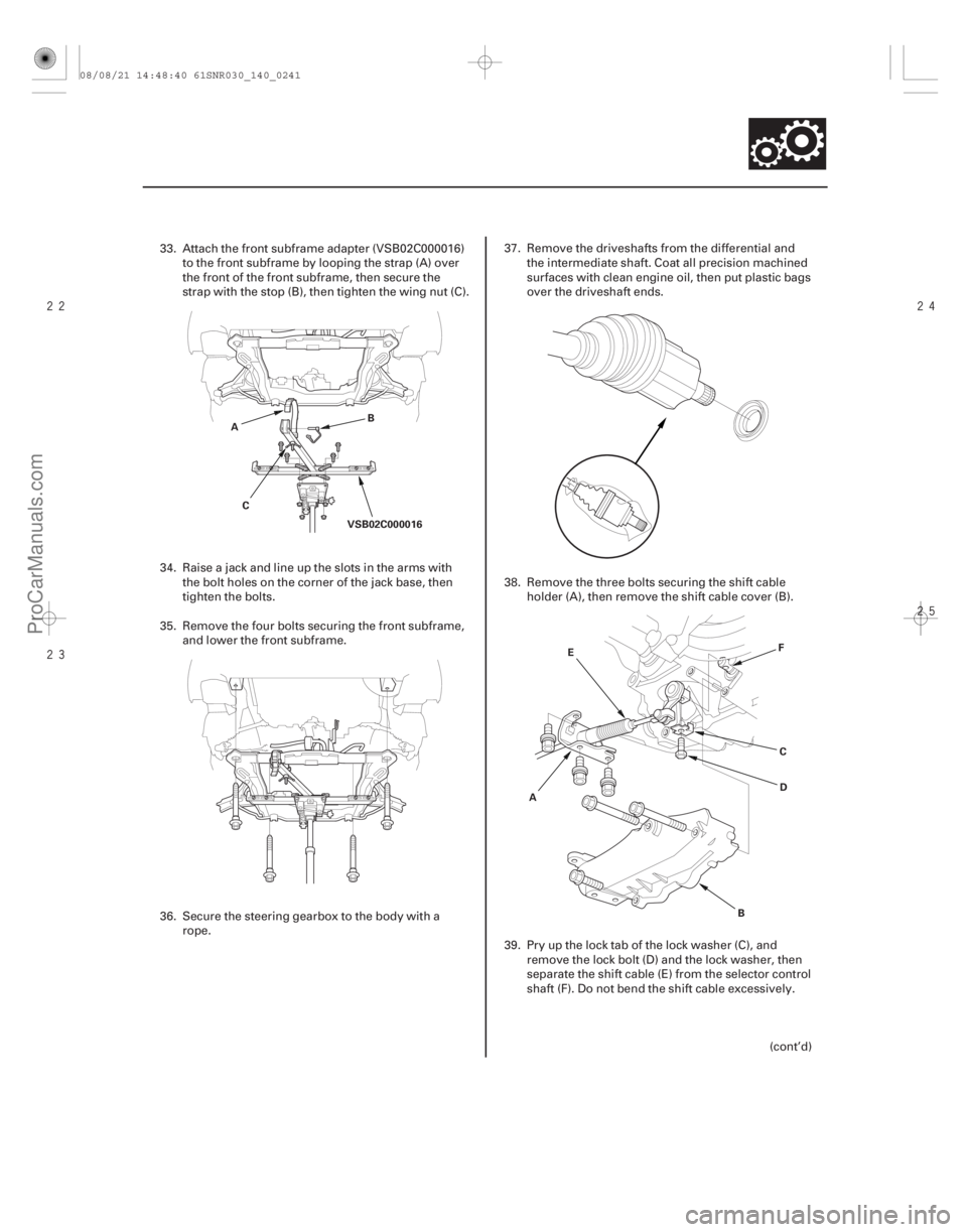
33. Attach the front subframe adapter (VSB02C000016)
to the front subframe by looping the strap (A) over
the front of the front subframe, then secure the
strap with the stop (B), then tighten the wing nut (C).
34. Raise a jack and line up the slots in the arms with the bolt holes on the corner of the jack base, then
tighten the bolts.
35. Remove the four bolts securing the front subframe, and lower the front subframe.
36. Secure the steering gearbox to the body with a rope. 37. Remove the driveshafts from the differential and
the intermediate shaft. Coat all precision machined
surfaces with clean engine oil, then put plastic bags
over the driveshaft ends.
38. Remove the three bolts securing the shift cable holder (A), then remove the shift cable cover (B).
39. Pry up the lock tab of the lock washer (C), and remove the lock bolt (D) and the lock washer, then
separate the shift cable (E) from the selector control
shaft (F). Do not bend the shift cable excessively.
(cont’d)
08/08/21 14:48:40 61SNR030_140_0241
ProCarManuals.com
DYNOMITE -2009-
Page 1160 of 2893
����
��������
14-244Automatic Transmission
Transmission Installation (cont’d)
12x1.25mm
59 N·m
(6.0 kgf·m, 43 lbf·ft)
10x1.25mm
39 N·m
(4.0 kgf·m, 29 lbf·ft)
E
8x1.25mm
22 N·m
(2.2 kgf·m, 16 lbf·ft)
F
8x1.25mm
22 N·m
(2.2 kgf·m, 16 lbf·ft)
D
8x1.25mm
22 N·m (2.2 kgf·m, 16 lbf·ft)
A
B
C A
B
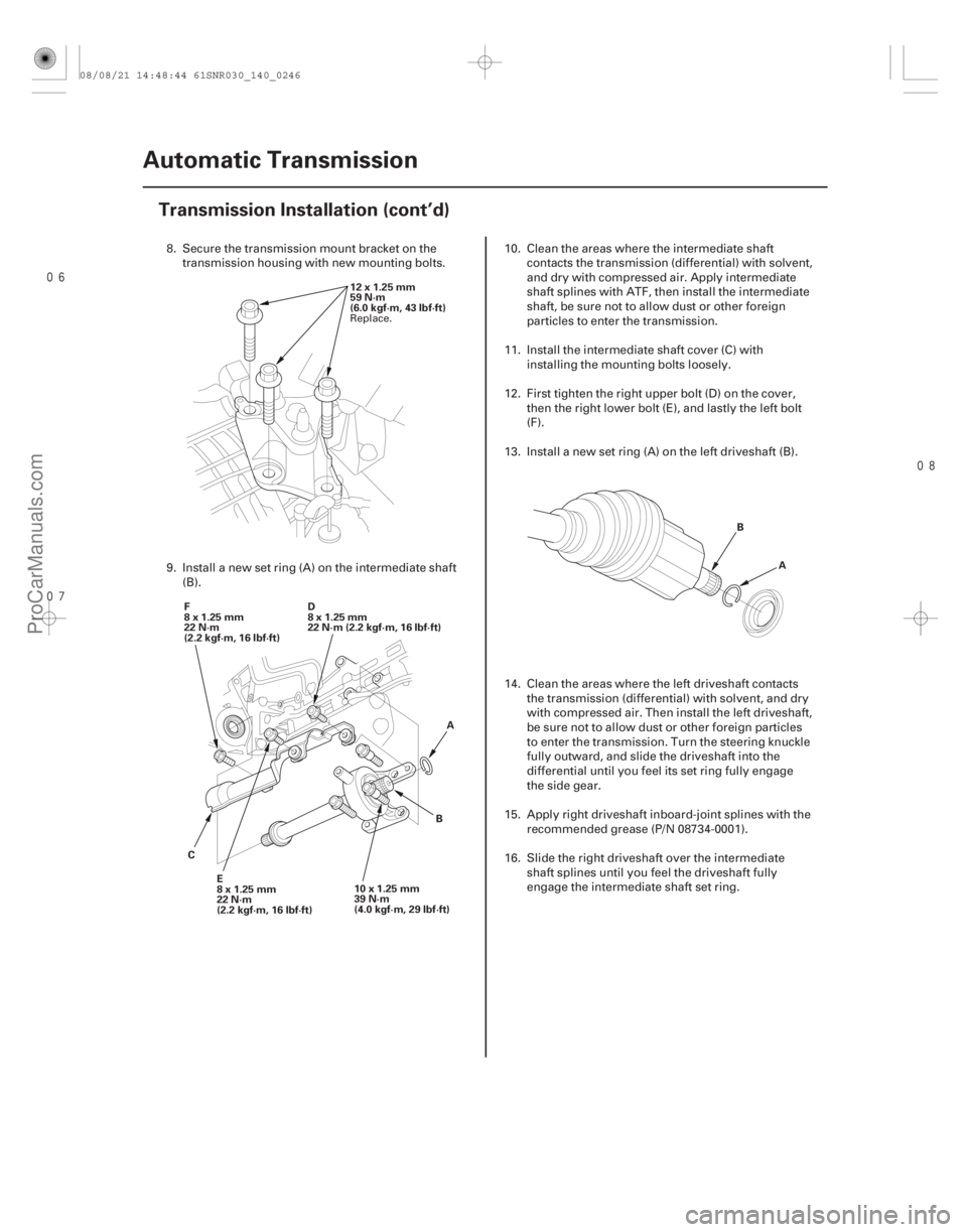
8. Secure the transmission mount bracket on the
transmission housing with new mounting bolts.
9. Install a new set ring (A) on the intermediate shaft (B). 10. Clean the areas where the intermediate shaft
contacts the transmission (differential) with solvent,
and dry with compressed air. Apply intermediate
shaft splines with ATF, then install the intermediate
shaft, be sure not to allow dust or other foreign
particles to enter the transmission.
11. Install the intermediate shaft cover (C) with installing the m ounting bolts loosely.
12. First tighten the right upper bolt (D) on the cover, then the right lower bolt (E), and lastly the left bolt
(F).
13. Install a new set ring (A) on the left driveshaft (B).
14. Clean the areas where the left driveshaft contacts the transmission (differential) with solvent, and dry
with compressed air. Then install the left driveshaft,
be sure not to allow dust or other foreign particles
to enter the transmission. Turn the steering knuckle
fully outward, and slide the driveshaft into the
differential until you feel its set ring fully engage
thesidegear.
15. Apply right driveshaft inboard-joint splines with the recommended grease (P/N 08734-0001).
16. Slide the right driveshaft over the intermediate shaft splines until you feel the driveshaft fully
engage the intermediate shaft set ring.
Replace.
08/08/21 14:48:44 61SNR030_140_0246
ProCarManuals.com
DYNOMITE -2009-
Page 1215 of 2893
����
��������
����
14-296
Transmission Housing
Housing and Shaft Assembly Removal (cont’d)
C
A
B
A
B A
BC
A
B
C
D
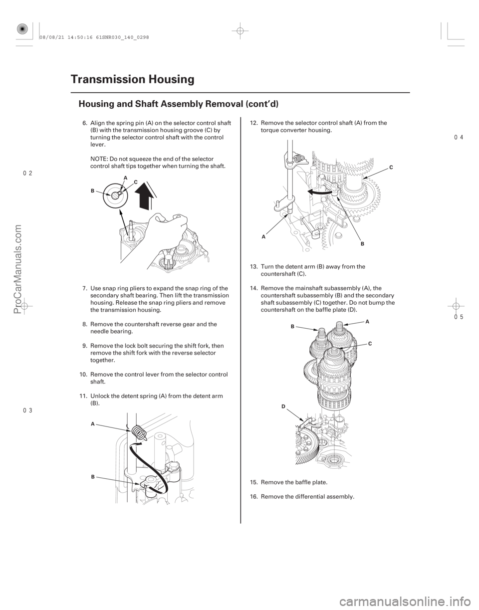
6. Align the spring pin (A) on the selector control shaft (B) with the transmission housing groove (C) by
turning the selector control shaft with the control
lever.
NOTE: Do not squeeze the end of the selector
control shaft tips together when turning the shaft.
7. Use snap ring pliers to expand the snap ring of the secondary shaft bearing. Then lift the transmission
housing. Release the snap ring pliers and remove
the transmission housing.
8. Remove the countershaft r everse gear and the
needle bearing.
9. Remove the lock bolt securing the shift fork, then remove the shift fork with the reverse selector
together.
10. Remove the control lever from the selector control shaft.
11. Unlock the detent spring (A) from the detent arm (B). 12. Remove the selector control shaft (A) from the
torque converter housing.
13. Turn the detent arm (B) away from the countershaft (C).
14. Remove the mainshaft subassembly (A), the countershaft subassembly (B) and the secondary
shaft subassembly (C) together. Do not bump the
countershaft on the baffle plate (D).
15. Remove the baffle plate.
16. Remove the differential assembly.
08/08/21 14:50:16 61SNR030_140_0298
ProCarManuals.com
DYNOMITE -2009-
Page 1269 of 2893
����
�(�#�'�������
���
�����
�������������
� �����)����
Exploded View
14-344Transmission Housing
Shaft Assembly and Housing Installation
TRANSMISSION HOUSING
MOUNTING BOLTS
10 x 1.25 mm
44 N·m(4.5 kgf·m, 33 lbf·ft)
19 Bolts
REVERSE
SHIFT FORK
SECONDARY
SHAFT
SUBASSEMBLY DIFFERENTIAL
ASSEMBLY TRANSMISSION
HANGER
MAINSHAFT
SUBASSEMBLY
NEEDLE
BEARING
REVERSE
SELECTOR
6x1.0mm
14 N·m
(1.4 kgf·m, 10 lbf·ft)
COUNTERSHAFT
REVERSE GEAR
COUNTERSHAFT
SUBASSEMBLY ATF FEED PIPE
ATF LUBRICATION PIPE
SHIFT SOLENOID
VALVE COVER
SELECTOR
CONTROL
SHAFT BAFFLE
PLATE
LOCK WASHER
TRANSMISSION
HOUSING
6x1.0mm
12 N·m
(1.2 kgf·m,
8.7 lbf·ft)
INPUT SHAFT
(MAINSHAFT)
SPEED SENSOR
OUTPUT SHAFT
(COUNTERSHAFT)
SPEED SENSOR
DETENT
SPRING
6x1.0mm
12 N·m
(1.2 kgf·m, 8.7 lbf·ft) 6x1.0mm
12 N·m
(1.2 kgf·m,
8.7 lbf·ft)
O-RING SHIFT
SOLENOID
WIRE
HARNESS
O-RING
O-RING6x1.0mm
12 N·m
(1.2 kgf·m,
8.7 lbf·ft) 6x1.0mm
12 N·m
(1.2 kgf·m,
8.7 lbf·ft)
Replace.
Replace.
Replace.
Replace.
08/08/21 14:52:30 61SNR030_140_0346
ProCarManuals.com
DYNOMITE -2009-
Page 1270 of 2893
���������
14-345
A
B
C
D 6x1.0mm
12 N·m (1.2 kgf·m, 8.7 lbf·ft)
B A
C E
F
D
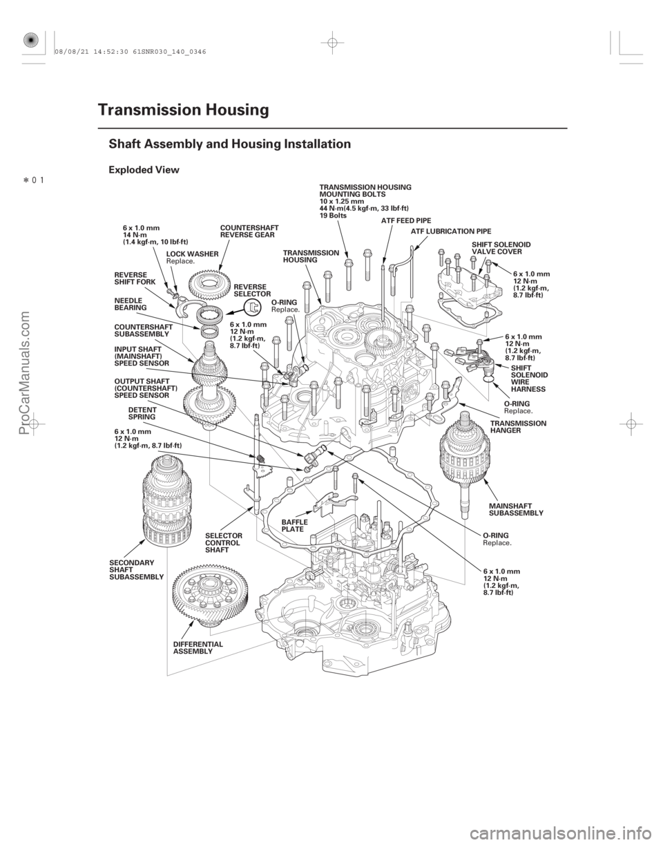
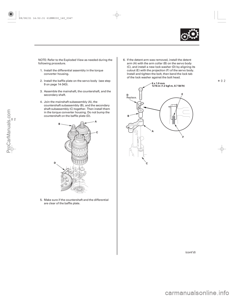
NOTE: Refer to the Exploded View as needed during the
following procedure.
1. Install the differential assembly in the torque converter housing.
2. Install the baffle plate on the servo body (see step 9 on page 14-343).
3. Assemble the mainshaft, the countershaft, and the secondary shaft.
4. Join the mainshaft subassembly (A), the countershaft subassembly (B), and the secondary
shaft subassembly (C) together. Then install them
in the torque converter housing. Do not bump the
countershaft on the baffle plate (D).
5. Make sure if the countershaft and the differential are clear of the baffle plate. 6. If the detent arm was removed, install the detent
arm (A) with the arm collar (B) on the servo body
(C), and install a new lock washer (D) by aligning its
cutout (E) with the projection (F) of the servo body.
Install and tighten the bolt, then bend the lock tab
of the lock washer against the bolt head.
(cont’d)
Replace.
08/08/21 14:52:31 61SNR030_140_0347
ProCarManuals.com
DYNOMITE -2009-
Page 1280 of 2893
����
�(�#�'�����������
�����
�
�������������������)���� ����
�(�#�'�����������
�����
�
�������������������)����
’06 Model ’07-09 Models
14-35514-355
A/T Differential
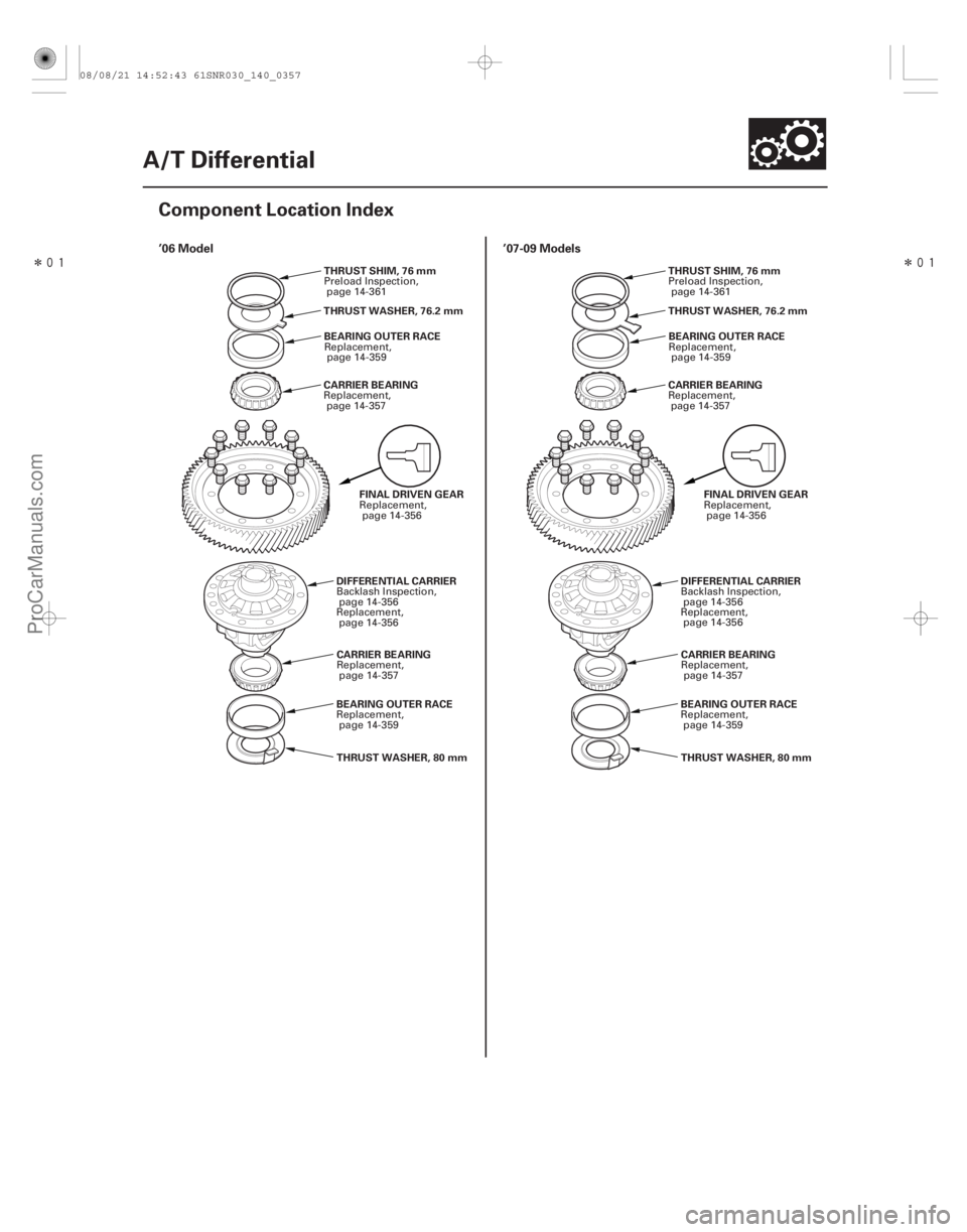
Component Location Index
THRUST SHIM, 76 mm
THRUST WASHER, 80 mm
BEARING OUTER RACE
CARRIER BEARING
CARRIER BEARING
BEARING OUTER RACE
THRUST WASHER, 76.2 mm
FINAL DRIVEN GEAR
DIFFERENTIAL CARRIER THRUST SHIM, 76 mm
THRUST WASHER, 80 mm
BEARING OUTER RACE
CARRIER BEARING
CARRIER BEARING
BEARING OUTER RACE
THRUST WASHER, 76.2 mm
FINAL DRIVEN GEAR
DIFFERENTIAL CARRIER
Preload Inspection,
page 14-361
Replacement, page 14-359
Replacement, page 14-357
Replacement,page 14-357
Replacement, page 14-359 Replacement,
page 14-356
Backlash Inspection, page 14-356
Replacement, page 14-356 Preload Inspection,
page 14-361
Replacement, page 14-359
Replacement, page 14-357
Replacement,page 14-357
Replacement, page 14-359 Replacement,
page 14-356
Backlash Inspection, page 14-356
Replacement, page 14-356
08/08/21 14:52:43 61SNR030_140_0357
ProCarManuals.com
DYNOMITE -2009-
Page 1281 of 2893
���
�(�#�'�������
���
�����
�
���
�������
�"�����)���� ���
�(�#�'�������
���
�����
�
���
�������
� �����)�
��
�µ�µ
Standard: 0.05 0.15 mm (0.002 0.006 in.)
14-35614-356 A/T Differential
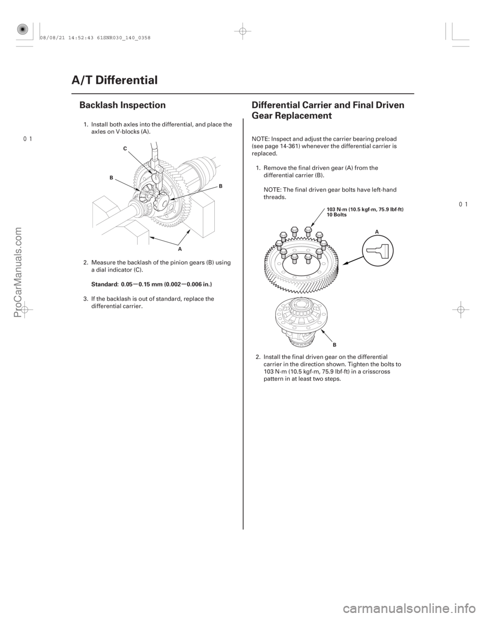
Backlash Inspection
Differential Carrier and Final Driven
Gear Replacement
A
B
C
B
A
B
103 N·m (10.5 kgf·m, 75.9 lbf·ft)
10 Bolts
1. Install both axles into the differential, and place the
axles on V-blocks (A).
2. Measure the backlash of the pinion gears (B) using a dial indicator (C).
3. If the backlash is out of standard, replace the differential carrier. NOTE: Inspect and adjust the carrier bearing preload
(see page 14-361) whenever the differential carrier is
replaced.
1. Remove the final driven gear (A) from the differential carrier (B).
NOTE: The final driven gear bolts have left-hand
threads.
2. Install the final driven gear on the differential carrier in the direction shown. Tighten the bolts to
103 N·m (10.5 kgf·m, 75.9 lbf·ft) in a crisscross
pattern in at least two steps.
08/08/21 14:52:43 61SNR030_140_0358
ProCarManuals.com
DYNOMITE -2009-