Page 1297 of 2893
����
��������
����
16-5
A
B
A
B
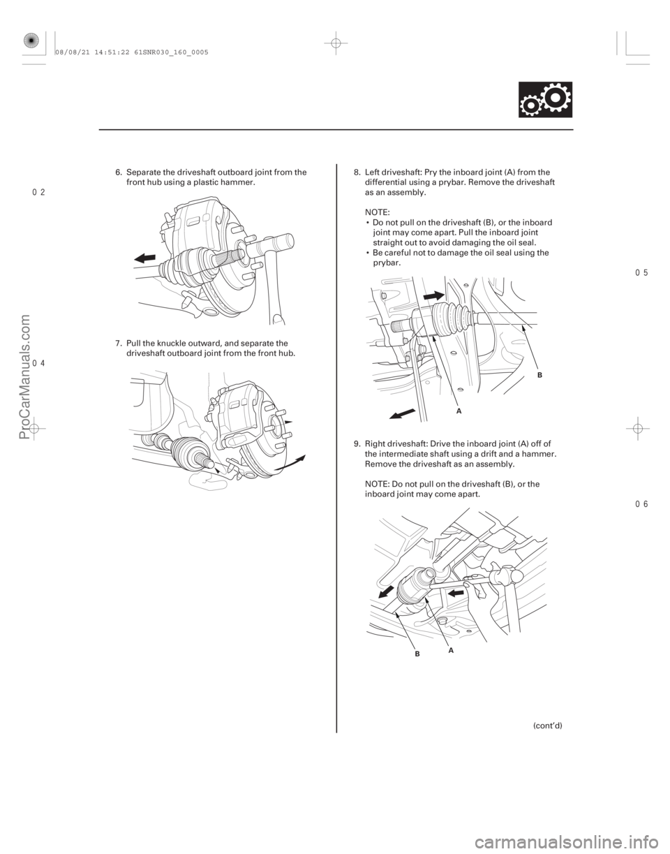
6. Separate the driveshaft outboard joint from the
front hub using a plastic hammer.
7. Pull the knuckle outward, and separate the driveshaft outboard joint from the front hub. 8. Left driveshaft: Pry the inboard joint (A) from the
differential using a prybar. Remove the driveshaft
as an assembly.
NOTE: Do not pull on the driveshaft (B), or the inboard joint may come apart. Pull the inboard joint
straight out to avoid damaging the oil seal.
Be careful not to damage the oil seal using the prybar.
9. Right driveshaft: Drive the inboard joint (A) off of the intermediate shaft using a drift and a hammer.
Remove the driveshaft as an assembly.
NOTE: Do not pull on the driveshaft (B), or the
inboard joint may come apart.
(cont’d)
08/08/21 14:51:22 61SNR030_160_0005
ProCarManuals.com
DYNOMITE -2009-
Page 1314 of 2893

C
12x1.25mm
59 N·m
(6.0 kgf·m,
43 lbf·ft)
D
12x1.25mm
59 N·m
(6.0 kgf·m,
43 lbf·ft)
A
B
5. Clean the areas")
���������
����
16-21
E
D A E
D
A
C B B
A
E
12x1.25mm
59 N·m
(6.0 kgf·m,
43 lbf·ft)
C
12x1.25mm
59 N·m
(6.0 kgf·m,
43 lbf·ft)
D
12x1.25mm
59 N·m
(6.0 kgf·m,
43 lbf·ft)
A
B
5. Clean the areas where the driveshaft contacts the
differential thoroughly with solvent or brake
cleaner, and dry with compressed air.
NOTE: Do not wash the rubber parts with solvent.
6. Insert the inboard end (A) of the driveshaft into the differential (B) or the intermediate shaft (C) until the
set ring (D) locks in the groove (E).
NOTE: Insert the driveshaft horizontally to prevent
damaging the oil seal. 7. Install the outboard joint (A) into the front hub (B).
8. Connect the knuckle (A) onto the lower arm (B).
During installation, install a new flange bolt and
new self-locking nuts. After lightly tightening all
three fasteners, tighten them to the specified
torque in the following order: the nut on the front
(C), the nut on the rear (D), then the bolt (E).
(cont’d)
Replace.
Replace.
Replace.
08/08/21 14:51:44 61SNR030_160_0021
ProCarManuals.com
DYNOMITE -2009-
Page 1316 of 2893
���
��������
�(�#�'�����������
��������������������� �����)����
16-23
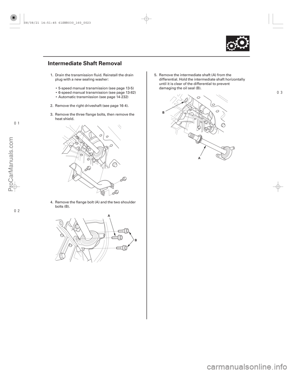
Intermediate Shaft Removal
A B A
B
1. Drain the transmission fluid. Reinstall the drain
plug with a new sealing washer:
5-speed manual transmission (see page 13-5)
6-speed manual transmission (see page 13-82)
Automatic transmission (see page 14-232)
2. Remove the right driveshaft (see page 16-4).
3. Remove the three flange bolts, then remove the heat shield.
4. Remove the flange bolt (A) and the two shoulder bolts (B). 5. Remove the intermediate shaft (A) from the
differential. Hold the intermediate shaft horizontally
until it is clear of the differential to prevent
damaging the oil seal (B).
08/08/21 14:51:45 61SNR030_160_0023
ProCarManuals.com
DYNOMITE -2009-
Page 1320 of 2893
���������
����
�(�#�'�����������
��������������������� �����)����
16-2716-27
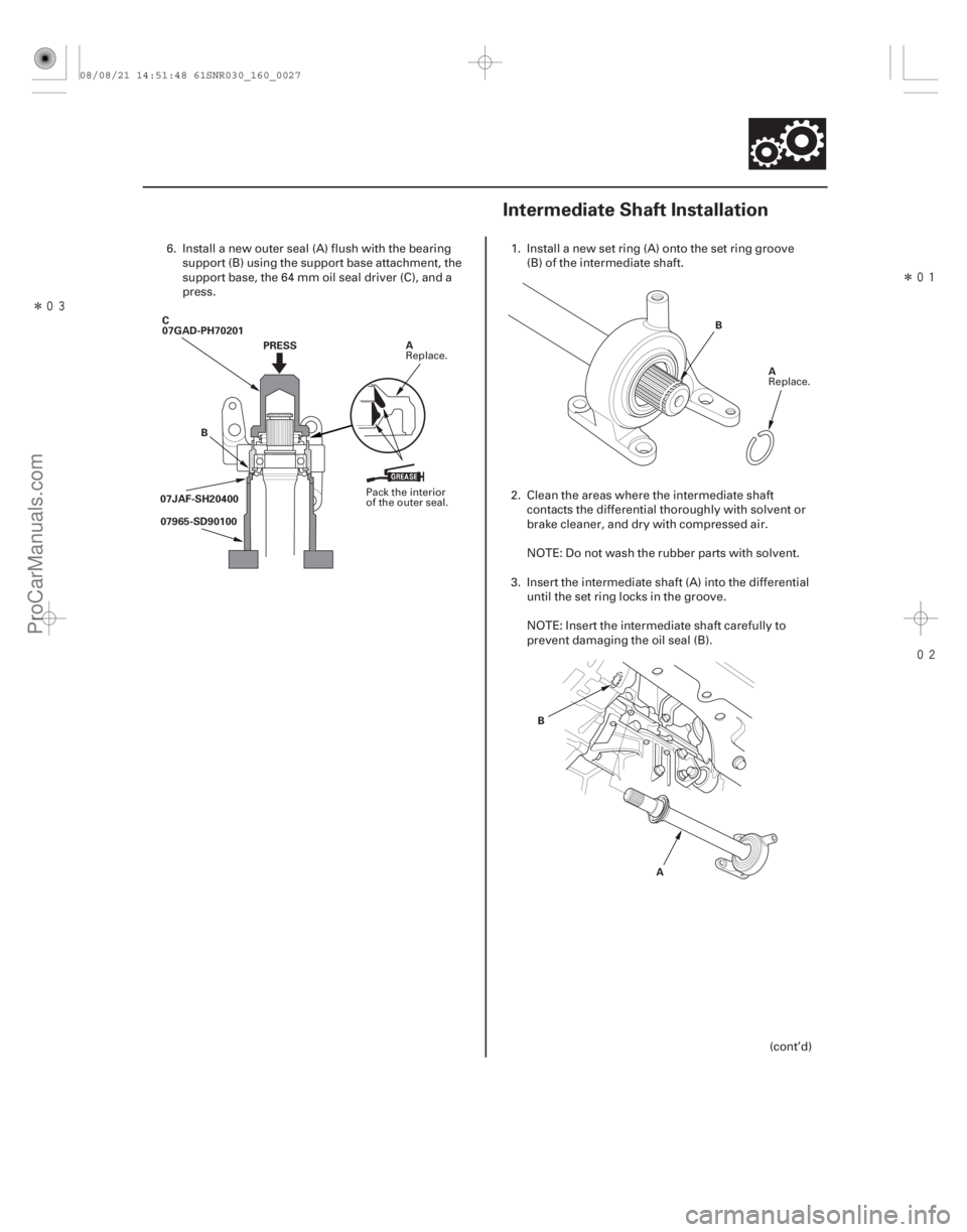
Intermediate Shaft Installation
PRESS
B
C
07GAD-PH70201
A
07JAF-SH20400 07965-SD90100 A
B
A
B
6. Install a new outer seal (A) flush with the bearing
support (B) using the support base attachment, the
support base, the 64 mm oil seal driver (C), and a
press. 1. Install a new set ring (A) onto the set ring groove
(B) of the intermediate shaft.
2. Clean the areas where the intermediate shaft contacts the differential thoroughly with solvent or
brake cleaner, and dry with compressed air.
NOTE: Do not wash the rubber parts with solvent.
3. Insert the intermediate shaft (A) into the differential until the set ring locks in the groove.
NOTE: Insert the intermediate shaft carefully to
prevent damaging the oil seal (B).
(cont’d)
Pack the interior
of the outer seal.Replace.
Replace.
08/08/21 14:51:48 61SNR030_160_0027
ProCarManuals.com
DYNOMITE -2009-
Page 1321 of 2893
���������
����
�(�#�'�����������
��������������������� �����)����
16-2716-27
Intermediate Shaft Installation
PRESS
B
C
07GAD-PH70201
A
07JAF-SH20400 07965-SD90100 A
B
A
B
6. Install a new outer seal (A) flush with the bearing
support (B) using the support base attachment, the
support base, the 64 mm oil seal driver (C), and a
press. 1. Install a new set ring (A) onto the set ring groove
(B) of the intermediate shaft.
2. Clean the areas where the intermediate shaft contacts the differential thoroughly with solvent or
brake cleaner, and dry with compressed air.
NOTE: Do not wash the rubber parts with solvent.
3. Insert the intermediate shaft (A) into the differential until the set ring locks in the groove.
NOTE: Insert the intermediate shaft carefully to
prevent damaging the oil seal (B).
(cont’d)
Pack the interior
of the outer seal.Replace.
Replace.
08/08/21 14:51:48 61SNR030_160_0027
ProCarManuals.com
DYNOMITE -2009-
Page 1347 of 2893

36-02 EPS Control Unit Internal Circuit (INH Output Circuit) (Initial Diagnosis) (see page 17-39)
37-01 EPS Control Unit")
DTCDetection Item Note
17-24EPS Components
DTC Troubleshooting Index (cont’d)
36-02 EPS Control Unit Internal Circuit (INH Output Circuit) (Initial Diagnosis) (see page 17-39)
37-01 EPS Control Unit Internal Circuit (Step-up Circuit) (Initial Diagnosis) (see page 17-39)
51-01 Low/High Voltage for the Torque Sensor (VT1 and VT2) (Regular
Diagnosis) (see page 17-46)
51-02 Torque Sensor (VT3 Differential-amplification Function) (Regular Diagnosis) (see page 17-50)
51-03 Torque Sensor (VT1, VT2 Rapid-change) (Regular Diagnosis) (see page 17-50)
51-06 Torque Sensor (VT1, VT2 Average) (Regular Diagnosis) (see page 17-50)
51-07 Torque Sensor (VT1, VT2 Initial Check) (Initial Diagnosis) (see page 17-50)
61-04 Open/Short in the EPS Motor Harness (Steering Diagnosis) (see page 17-53)
71-01 EPS Motor Angle Sensor (SIN/COS Signals) (Steering Diagnosis) (see page 17-55)
71-02 EPS Motor Angle Sensor (Neutral Position Learning of SIN/COS) (Initial Diagnosis) (see page 17-55)
71-03 EPS Motor Angle Sensor (SIN/COS Signals) (Steering Diagnosis) (see page 17-55)
71-04 EPS Motor Angle Sensor (Check Signals) (Regular Diagnosis) (see page 17-58)
71-05 EPS Motor Angle Sensor (SIN/COS Signals Charging Amount) (Steering Diagnosis) (see page 17-55)
71-06 EPS Motor Angle Sensor (Neutral Position of SIN/COS) (Initial Diagnosis) (see page 17-55)
NOTE: Initial diagnosis: Done right after the engine starts and until the EPS indicator goes off.
Regular diagnosis: Done right after the initial diagnosis until the ignition switch is turned to LOCK (0).
Steering diagnosis: Done during regular diagnosis while turning steering wheel.
08/08/21 14:53:59 61SNR030_170_0025
ProCarManuals.com
DYNOMITE -2009-
Page 1373 of 2893
���
�µ
�µ
�µ
�µ �µ
�µ
�µ
�µ
DTC 51-02:
DTC 51-03:
DTC 51-06:
DTC 51-07:
YES
NO
YES
NO YES
NO
YES
NO
17-50EPS Components
DTC Tro")
�µ
�µ
���
����
�(�#�'��������� �������������'���
�����������)���
�µ
�µ
�µ
�µ �µ
�µ
�µ
�µ
DTC 51-02:
DTC 51-03:
DTC 51-06:
DTC 51-07:
YES
NO
YES
NO YES
NO
YES
NO
17-50EPS Components
DTC Troubleshooting (cont’d)
EPS CONTROL UNIT CONNECTOR D (28P)
PVF (BRN) VS1 (GRN)
EPS CONTROL UNIT CONNECTOR D (28P)
PVF (BRN)
VS2 (LT GRN)
Torque Sensor (VT3 Differential-
amplification Function) (Regular Diagnosis)
Torque Sensor (VT1, VT2 Rapid
Change) (Regular Diagnosis)
Torque Sensor (VT1, VT2
Average) (Regular Diagnosis)
Torque Sensor (VT1, VT2 Initial
Check) (Initial Diagnosis)
1. Turn the ignition switch to ON (II).
2. Clear the DTC with the HDS.
3. Turn the ignition switch to LOCK (0).
4. Start the engine.
Go to step 5.
Check for loose terminals or poor connections.
If the connections are good, the system is OK at
this time.
5. Check for DTCs with the HDS.
Go to step 6.
Troubleshoot the indicated DTC. If there are
no DTCs, the system is OK at this time.
6. Turn the ignition switch to LOCK (0). 7. Disconnect EPS control unit connector D (28P).
8. Measure the resistance between EPS control unit
connector D (28P) terminals No. 9 and No. 10.
Go to step 9.
Go to step 13.
9. Measure the resistance between EPS control unit connector D (28P) terminals No. 8 and No. 9.
Go to step 10.
Go to step 15.
Wire side of female terminals
Wire side of female terminals
Does t he E PS i nd i cat or come on?
I s DT C 5 1-02, 5 1-03, 5 1-06, or 5 1-07 i nd i cat ed ? Is t he r esi st ance bet w een 12 15 ?
Is t he r esi st ance bet w een 12 15 ?
08/08/21 14:54:35 61SNR030_170_0051
ProCarManuals.com
DYNOMITE -2009-