Page 2120 of 2893

HID UNIT 2P CONNECTOR
LEFT HEADLIGHT (PUR)
RIGHT HEADLIGHT (")
��������
����
�µ
�µ
�µ
�µ
YES
NO
LEFT HEADLIGHT
RIGHT HEADLIGHT
YES
NO
22-172Exterior Lights
HID Lamp System Troubleshooting (cont’d)
HID UNIT 2P CONNECTOR
LEFT HEADLIGHT (PUR)
RIGHT HEADLIGHT (GRN)
HID UNIT 2P CONNECTOR (LEFT HEADLIGHT)PUR
UNDER-DASH FUSE/RELAY BOX CONNECTOR G (21P)
UNDER-DASH FUSE/RELAY BOX CONNECTOR F (34P) HID UNIT 2P CONNECTOR (RIGHT HEADLIGHT) GRN
16. Measure the voltage between the HID unit 2P
connector terminal No. 2 and body ground.
Substitute a known-good HID unit, and
recheck. If the symptom/indication goes away,
replace the original HID unit.
Go to step 17.
17. Disconnect under-dash fuse/relay box connector G (21P) and/or F (34P) .1: Left headlight
2: Right headlight 18. Check for continuity between under-dash fuse/relay
box G (21P) terminal No. 17 or F (34P) terminal
No. 4 and HID unit 2P connector terminal No. 2.
Replace the under-dash fuse/relay box.
Repair an open in the wire between the
under-hood fuse/relay box and the HID unit.
12
Wire side of female terminals
Wire side of female terminalsWire side of female terminals
Wire side of female terminals Wire side of female terminals
Is there battery voltage?
Is there continuity?
08/08/21 14:27:00 61SNR030_220_0174
ProCarManuals.com
DYNOMITE -2009-
Page 2134 of 2893
������(�#�'���������������
�����������������������)����
�´
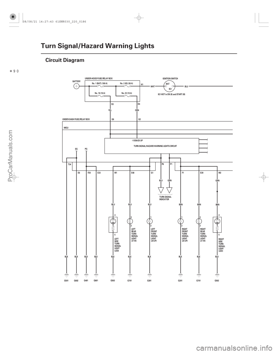
22-184Turn Signal/Hazard Warning Lights
Circuit Diagram
4
5
5 4
G701BLU
3
2E40
BLK E39
2 3
BRN
G701 BLK
T34
G602BLKSG
E6
G501 BLK TURN SIGNAL/HAZARD WARNING LIGHTS CIRCUIT
G2
G6
BLK
BLK
BLK
BLK
BLK WHT
IG1 HOT in ON (II) and START (III)
P1
P6
M2
G502
F1
G201 2
1
BRN
GRN
BLU
G1
G301 BLU
1
2
MICU
UNDER-DASH FUSE/RELAY BOX IG1
BAT
IGNITION SWITCH
BLU
No. 10 (10 A)
E33
F20
PG
G601 BBACKUP
ORN
M1
YEL
BLK
G401 BLUNo. 23 (10 A)
BATTERY
No. 1 (BAT) (100 A)
UNDER-HOOD FUSE/RELAY BOX
No. 2 (IG) (50 A)
G503 TURN SIGNAL
INDICATOR
LEFT
SIDE
TURN
SIGNAL
LIGHT
(LED) RIGHT
SIDE
TURN
SIGNAL
LIGHT
(LED)
RIGHT
FRONT
TURN
SIGNAL
LIGHT
(24 CP)
LEFT
FRONT
TURN
SIGNAL
LIGHT
(24 CP) RIGHT
REAR
TURN
SIGNAL
LIGHT
(21 W)
LEFT
REAR
TURN
SIGNAL
LIGHT
(21 W) H1
D4
D3
BRN
GRN
08/08/21 14:27:43 61SNR030_220_0186
ProCarManuals.com
DYNOMITE -2009-
Page 2141 of 2893

Cavity Wire Test conditionTest: Desired result Possible cause if desired result is
not obtained
22-191
6. Reconnect connectors to the under-dash fuse/relay box, and do these input tests at the following connectors.
If any test indicates a problem, find and correct the cause, then recheck the system.
If all the input tests prove OK, the MICU must be faulty; replace the under-dash fuse/relay box.
G2 ORN Under all conditions Measure the voltage between
terminal G2 and body ground:
There should be battery voltage.Blown No. 23 (10 A) fuse in the
under-hood fuse/relay box
An open in the wire
G6 YEL Under all conditions Measure the voltage between terminal G6 and body ground:
There should be battery voltage.Blown No. 10 (10 A) fuse in the
under-hood fuse/relay box
An open in the wire
E6 BLK Under all conditions Measure the voltage to ground: There should be less than 0.5 V.Poor ground (G602)
An open in the wire
E33 BLK Under all conditions Measure the voltage to ground: There should be less than 0.5 V.Poor ground (G601)
An open in the wire
F20 BLK Under all conditions Measure the voltage to ground: There should be less than 0.5 V.Poor ground (G401)
An open in the wire
T34 BLK Under all conditions Measure the voltage to ground: There should be less than 0.5 V.Poor ground (G501)
An open in the wire
R1 WHT Under all conditions Measure the voltage to ground: There should be battery voltage.Faulty under-dash fuse/relay box
Q11 GRN Hazard warning switch ON Measure the voltage to ground:
There should be battery voltage. Blown No. 23 (10 A) fuse in the
under-hood fuse/relay box
Faulty hazard warning switch
An open in the wire
S18 ·
S5 BRN
·
BLK Turn signal switch in
right position
Measure the voltage between
terminals S18 and S5:
There should be less than 0.5 V. Faulty combination light switch
An open in the wire
Turn signal switch in
left or neutral
position Measure the voltage between
terminals S18 and S5:
There should be 5 V or more. Faulty combination light switch
A short to ground in the wire
S19 ·
S5 LT
GRN ·
BLK Turn signal switch in
left position
Measure the voltage between
terminals S19 and S5:
There should be less than 0.5 V. Faulty combination light switch
An open in the wire
Turn signal switch in
right or neutral
position Measure the voltage between
terminals S19 and S5:
There should be 5 V or more. Faulty combination light switch
A short to ground in the wire
08/08/21 14:27:44 61SNR030_220_0193
ProCarManuals.com
DYNOMITE -2009-
Page 2144 of 2893
�
�
22-194Interior Lights
Circuit Diagram
D A
B
A C
GRNMICU
UNDER-DASH FUSE/RELAY BOX
GRNE37 E3
LT GRN BRNE17 E2
GRYK4
(8 W) (8 W)
1
(Without moon")
������(�#�'���������������������������������������)�
�
22-194Interior Lights
Circuit Diagram
D A
B
A C
GRNMICU
UNDER-DASH FUSE/RELAY BOX
GRNE37 E3
LT GRN BRNE17 E2
GRYK4
(8 W) (8 W)
1
(Without moonroof)
LT BLU
PNKDOOR
OFF
PNK
BLU
3
LT BLU LT BLU
LT BLU
(With moonroof)
1
2
(8 W) (8 W)
PNK 1
ON OFF
(8 W) RED
UNDER-HOOD FUSE/RELAY BOX
No. 22 (7.5 A)
No. 1 (BAT) (100 A)
BATTERY
CEILING
LIGHT
INTERIOR
LIGHT SWITCH
(In the moonroof
switch)
RIGHT REAR
DOOR
SWITCH
(Closed:
Door open)
LEFT REAR
DOOR
SWITCH
(Closed:
Door open)
FRONT
PASSENGER’S
DOOR SWITCH
(Closed:
Door open)
DRIVER’S
DOOR
SWITCH
(Closed:
Door open) D2
1 1
1
9*2 8*1
1*1
7*2 LT BLU
LT BLU
FRONT
PASSENGER’S
DOOR
COURTESY
LIGHT LT BLU
VANITY
MIRROR
LIGHTS *2
No. 22 (7.5 A)FUSE
(UNDER-HOOD
FUSE/RELAY BOX) LT BLU
GRN (3.4 W)
DRIVER’S
DOOR
COURTESY
LIGHT
GRN1 No. 22 (7.5 A)FUSE
(UNDER-HOOD
FUSE/RELAY BOX)
LT GRN
GRN (3.4 W)
FRONT
PASSENGER’S
DOOR
COURTESY
LIGHT BLU
BLK 3
2
G701 E36
BLU TRUNK LID
LATCH
SWITCH
(Closed:
Trunk lid open)BLU
TRUNK
LIGHT
FRONT
INDIVIDUAL
MAP LIGHTS
FRONT
INDIVIDUAL
MAP LIGHTS
08/08/21 14:27:49 61SNR030_220_0196
ProCarManuals.com
DYNOMITE -2009-
Page 2148 of 2893
���� ���
�(�#����������������������������
���
� �����)���� Courtesy light: 3.4 W
22-19822-198
Interior Lights
Ambient Light Test/Replacement Cour")
����
�(�#�'�����������������������
���������������)���� ���
�(�#�'���������������������������
���
� �����)���� Courtesy light: 3.4 W
22-19822-198
Interior Lights
Ambient Light Test/Replacement Courtesy Light Replacement
A
B
C ’06-07 models
’08-09 models
A
B C
D
1. Remove the front individual map light.
With moonroof (see page 22-196)
Without moonroof (see page 22- 196)
2. Disconnect the 10P (or 12P ) connector (A) from the ambient light (B), then remove the ambient
light from the front individual map light housing (C).
1: ’06-07 models
2: ’08-09 models
3. Connect battery power to the terminal No. 5 and ground to the No. 3 terminal. The ambient light
should turn on. If the light does not turn on, replace
the ambient light.
4. Install the ambient light in the reverse order of removal. 1. Carefully pry off the lens (A) with a small
screwdriver.
2. Pry out the housing (B) from the door panel, then disconnect the 2P connector (C).
3. Separate the housing, then remove the bulb (D) from the socket.
4. Install the courtesy light in the reverse order of removal.
12
08/08/21 14:27:50 61SNR030_220_0200
ProCarManuals.com
DYNOMITE -2009-
Page 2153 of 2893
����
�µ
�µ
22-203
Circuit Diagram
5 6
R13
ORN
LT BLU
BLK5
7
G501 LOCK
WHT
T23
BRN T24
LT GRN
6
4
UNDER-DASH FUSE/RELAY BOX 7*2
1*1 8*1
9*2K5
G3 D")
����
�(�#�'���������������������������������������)����
�µ
�µ
22-203
Circuit Diagram
5 6
R13
ORN
LT BLU
BLK5
7
G501 LOCK
WHT
T23
BRN T24
LT GRN
6
4
UNDER-DASH FUSE/RELAY BOX 7*2
1*1 8*1
9*2K5
G3 D2
PG
SG
PNKR16
G501 BLK
T34
BLK
G401 F20
E2
GRY
LT BLU LT BLU
CEILING LIGHT BLU
PNK FRONT
INDIVIDUAL
MAP LIGHTS
PNKDOOR
IG1Q6
B-CAN
No. 22 (7.5 A)
No. 2 (IG) (50 A)
No. 1 (BAT) (100 A)
OFFUNDER-DASH FUSE/RELAY BOX
(7.5 A) No. 10
PNK
PNK RED
BLU
BRN E17
E33 R6
G601 BLK
E6
BLK
G602 K4
MICU
E3
E37
GRN LT GRN
G504BLKPNK
1
2
WHT
IG1
BAT
UNDER-HOOD FUSE/RELAY BOX
BATTERY IGNITION SWITCH
IG1 HOT in ON (II)
and START (III)
INTERIOR
LIGHT
SWITCH IMMOBILIZER-
KEYLESS CONTROL
UNIT
DRIVER’S
DOOR
SWITCH
(Closed:
Door open) FRONT
PASSENGER’S
DOOR SWITCH
(Closed:
Door open) LEFT
REAR DOOR
SWITCH
(Closed:
Door open)RIGHT
REAR DOOR
SWITCH
(Closed:
Door open) IGNITION
KEY
SWITCH
(Closed:
Key inserted)IMMOBILIZER-
KEYLESS
CONTROL
UNIT
DRIVER’S
DOOR
LOCK
KNOB
SWITCH
UN-
LOCK
IGNITION
KEY LIGHT
(LED)
H1
D2
1 111 :CANline
*1: ’06 07 models
*2: ’08 09 models
TRANSMITTER
08/08/21 14:27:54 61SNR030_220_0205
ProCarManuals.com
DYNOMITE -2009-
Page 2162 of 2893
�����(�#�'���������������������������������������)����
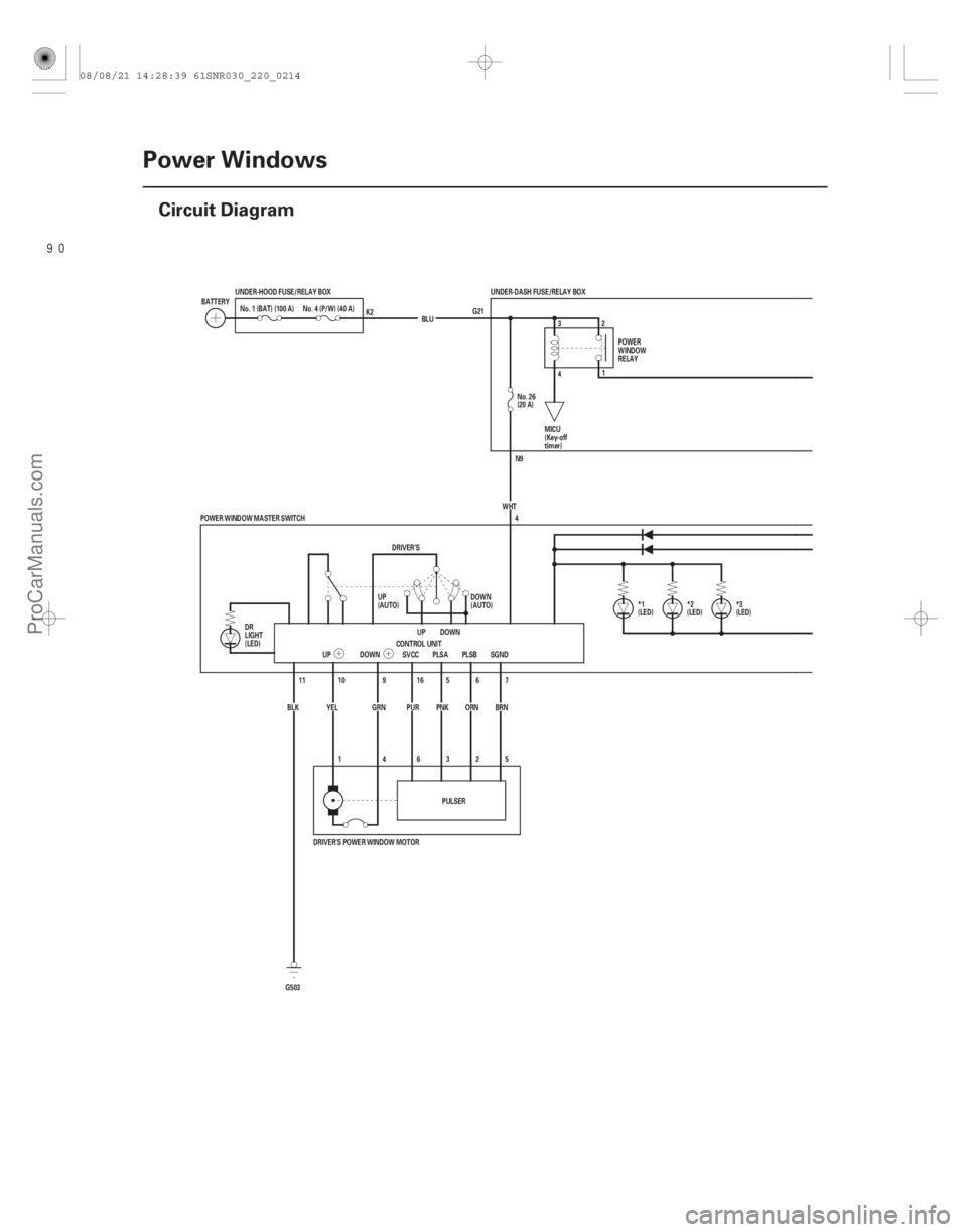
22-212Power Windows
Circuit Diagram
G21
N9
5
2
3
6
4
1
11
(LED) *3
(LED)
*1 *2 (LED)
UNDER-DASH FUSE/RELAY BOX
BLU
No. 4 (P/W) (40 A)
UNDER-HOOD FUSE/RELAY BOX
No. 1 (BAT) (100 A)
BATTERY
CONTROL UNITDOWN
UP
DRIVER’S
YEL GRN PUR
PNKORN
UP DOWN SVCC PLSA PLSB
6
5
16
9
10 4
POWER WINDOW MASTER SWITCH No. 26
(20 A)
WHT
PULSER
BLK
G503 7
SGND
BRN POWER
WINDOW
RELAY
DOWN
(AUTO)
UP
(AUTO) MICU
(Key-off
timer)
DR
LIGHT
(LED) K2
DRIVER’S POWER WINDOW MOTOR 32
4 1
08/08/21 14:28:39 61SNR030_220_0214
ProCarManuals.com
DYNOMITE -2009-
Page 2166 of 2893

5. Reconnect")
�µ
�µ�µ
�µ
�µ�µ
Cavity Wire Test condition Test: Desired result Possible cause if desired result is not
obtained
22-216Power Windows
Power Window Master Switch Input Test (cont’d)
5. Reconnect the 22P connector to the power window master switch. Turn the ignition switch to ON (II), and do these input tests at the
following connector.
If any test indicates a problem, find and correct the cause, then recheck the system.
If all the input tests prove OK, the control unit must be faulty; replace the power window master switch.
3 GRN Ignition switch ON (II) Measure the voltage to ground:
There should be battery voltage.Blown No. 30 (20 A) fuse in the under-
dash fuse/relay box
Faulty power window relay
Faulty MICU
An open in the wire
4 WHT Under all conditions Measure the voltage to ground: There should be battery voltage.Blown No. 26 (20 A) fuse in the under-
dash fuse/relay box
An open in the wire
15 RED Ignition switch ON (II) Measure the voltage to ground: There should be battery voltage.Blown No. 32 (20 A) fuse in the under-
dash fuse/relay box
Faulty power window relay
Faulty MICU
An open in the wire
20 PUR Ignition switch ON (II) Measure the voltage to ground: There should be battery voltage.Blown No. 33 (20 A) fuse in the under-
dash fuse/relay box
Faulty power window relay
Faulty MICU
An open in the wire
7 BRN Under all conditions Measure the voltage to ground: There should be less than 0.5 V.Poor ground (G503)
An open in the wire
11 BLK Under all conditions Measure the voltage to ground: There should be less than 0.5 V.Poor ground (G503)
An open in the wire
12 BLK Under all conditions Measure the voltage to ground: There should be less than 0.5 V.Poor ground (G503)
An open in the wire
16 PUR Ignition switch ON (II) Measure the voltage to ground: There should be battery voltage.Faulty power window master switch
A short to ground in the wire
5 PNK Ignition switch ON (II), and driver’s power window switch
moving up or down Measure the voltage between
terminals No. 5 and No. 7:
There should be 0 V about
5 V 0 V about 5 V repeatedly
(a digital voltmeter should read
about 2.5 V while the window
moves). Faulty power window master switch
Faulty driver’s power window motor
An open in the wire
A short to ground in the wire
6 ORN Ignition switch ON (II), and driver’s power window switch
moving up or down Measure the voltage between
terminals No. 6 and No. 7:
There should be 0 V about
5 V 0 V about 5 V repeatedly
(a digital voltmeter should read
about 2.5 V while the window
moves).
6. Reset the power window control unit (see page 22-210).
08/08/21 14:28:40 61SNR030_220_0218
ProCarManuals.com
DYNOMITE -2009-