Page 2081 of 2893

Cavity Wire Test conditionTest: Desired result Possible cause if desired result is
not obtained
22-133
5. With the connector still disconnected, do these input tests at the following connectors.
If any test indicates a problem, find and correct the cause, then recheck the system.
If all the input tests prove OK, go to step 6.
G16 WHT Under all
conditions Measure the voltage to ground:
There should be battery voltage. Blown No. 12 (15 A) fuse in the
under-hood fuse/relay box
An open in the wire
G18 WHT Under all conditions Measure the voltage to ground:
There should be battery voltage. Blown No. 4 (50 A) fuse in the
under-hood fuse/relay box
An open in the wire
G7 LT GRNUnder all
conditions Connect terminals G16 and G7
with a jumper wire
momentarily:
The horn should sound. Poor ground (body ground)
Blown No. 12 (15 A) fuse in the
under-hood fuse/relay box
Faulty horn
An open in the wire
E20 GRN Under all conditions Connect terminals G2 and E20
with a jumper wire:
The trunk release actuator
should work (Trunk lid should
open). Poor ground (G701)
Faulty trunk release actuator
An open in the wire
N7 BLU Under all conditions Connect battery power to
terminal N13 and ground
terminal N7 momentarily:
The driver’s door lock actuator
should unlock. Faulty driver’s door lock
actuator
An open in the wire
N13 YEL
M8 YEL Under all conditions Connect battery power to
terminal M8 and ground
terminal M10 momentarily:
The front passenger’s door lock
actuator should unlock. Faulty front passenger’s door
lock actuator
An open in the wire
M10 BLU
E1 YEL Under all conditions Connect battery power to
terminal E1 and ground
terminal E21 momentarily:
The right rear door lock actuator
should unlock. Faulty right rear door lock
actuator
An open in the wire
E21 BLU
E14 YEL Under all
conditions Connect battery power to
terminal E14 and ground
terminal E31 momentarily:
The left rear door lock actuator
should unlock. Faulty left rear door lock
actuator
An open in the wire
E31 BLU
(cont’d)
08/08/21 14:26:04 61SNR030_220_0135
ProCarManuals.com
DYNOMITE -2009-
Page 2085 of 2893
����
Driver’s Door and Left Rear Door Front Passenger’s Door and Right Rear Door
22-137
Door Lock Actuator Test
A
B
Terminal
Pos")
���
��������
����
�(�#�'�������������������������������
�������)����
Driver’s Door and Left Rear Door Front Passenger’s Door and Right Rear Door
22-137
Door Lock Actuator Test
A
B
Terminal
Position 12
LOCK
UNLOCK A
B
Terminal
Position 34
LOCK
UNLOCK
1. Remove the door panel (see page 20-7).
2. Disconnect the 10P connector (A) from the actuator (B).
NOTE: The illustration shows the driver’s door.
3. Check actuator operation by connecting power and ground according to the table. To pr event damage
to the actuator, apply battery voltage only
momentarily.
4. If the actuator does not operate as specified, replace it. 1. Remove the door panel.
Front door panel (see page 20-7)
Rear door panel (see page 20-17)
2. Disconnect the 10P connector (A) from the actuator (B).
NOTE: The illustration shows the front passenger’s
door.
3. Check actuator operation by connecting power and ground according to the table. To prevent damage
to the actuator, apply battery voltage only
momentarily.
4. If the actuator does not operate as specified, replace it.
08/08/21 14:26:05 61SNR030_220_0139
ProCarManuals.com
DYNOMITE -2009-
Page 2090 of 2893
����
With HDS
22-142 Keyless/Power Door Locks/Security System
Transmitter Test/Replacement
A
NOTE:
If the doors unlock or lock with the transm")
���
����
�(�#�'���������������������������
���
�������)����
With HDS
22-142 Keyless/Power Door Locks/Security System
Transmitter Test/Replacement
A
NOTE:
If the doors unlock or lock with the transmitter, but the LED on the transmitter does not come on, the LED
is faulty; replace the transmitter.
If any door is open, you cannot lock the doors with the transmitter.
If you unlocked the doors with the transmitter, but do not open any of the doors within 30 seconds, the
doors relock automatically.
The doors do not lock or unlock with the transmitter if the ignition key is inserted in the ignition switch.
1. Press the lock or unlock button five or six times to reset the transmitter.
If the locks work, the transmitter is OK.
If any of the transmitter buttons do not work, replace the transmitter, then do the transmitter
programming registration (see page 22-329).
If the locks don’t work, go to step 2.
2. Connect the HDS to the data link connector.
3. Select the KEYLESS from the BODY ELECTRICAL menu, then enter the KEYLESS CHECK.
4. Press lock, unlock, trunk, or panic button and check the response on the screen of the HDS.
NOTE: The door lock actuators may or may not
cycle when receiving input from the transmitter.
If KEYLESS ENTRY TRANSMITTER CODE IS RECEIVED is indicated, the transmitter is OK. Go
to keyless operation troubleshooting (see page
22-127).
If DIFFERENT KEYLESS ENTRY TRANSMITTER CODE IS RECEIVED is indicated, the transmitter is
not registered to the vehicle, if necessary,
reprogram and register the transmitter (see page
22-329).
If KEYLESS ENTRY TRANSMITTER CODE IS NOT RECEIVED is indicated, go to step 5. 5. Open the transmitter and check for water damage.
If you find any water damage, replace thetransmitter, then reprogram and register the
transmitter (see page 22-329).
If there is no water damage, go to step 6.
6. Replace the transmitter battery (A) with a new one, and press lock or unlock button and check the
receive condition on the screen of the HDS.
If KEYLESS ENTRY TRANSMITTER CODE IS RECEIVED is indicated, the transmitter is OK.
If KEYLESS ENTRY TRANSMITTER CODE IS NOT RECEIVED is indicated, go to step 7.
08/08/21 14:26:07 61SNR030_220_0144
ProCarManuals.com
DYNOMITE -2009-
Page 2092 of 2893
����
22-144Keyless/Power Door Locks/Security System
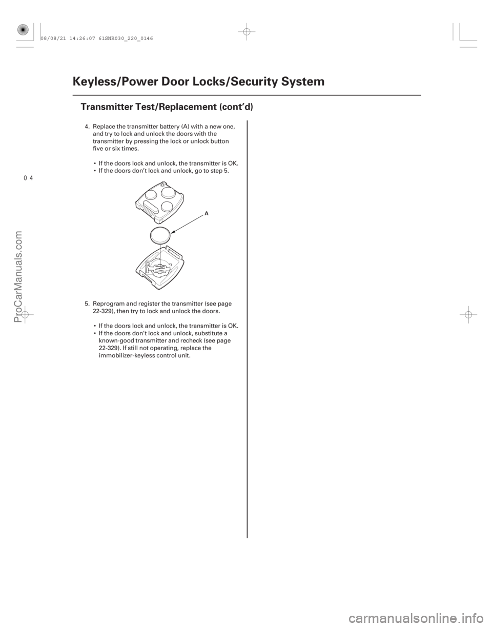
Transmitter Test/Replacement (cont’d)
A
4. Replace the transmitter battery (A) with a new one,
and try to lock and unlock the doors with the
transmitter by pressing the lock or unlock button
five or six times.
If the doors lock and unlock, the transmitter is OK.
If the doors don’t lock and unlock, go to step 5.
5. Reprogram and register the transmitter (see page 22-329), then try to lock and unlock the doors.
If the doors lock and unlock, the transmitter is OK.
If the doors don’t lock and unlock, substitute a known-good transmitter and recheck (see page
22-329). If still not operating, replace the
immobilizer-keyless control unit.
08/08/21 14:26:07 61SNR030_220_0146
ProCarManuals.com
DYNOMITE -2009-
Page 2094 of 2893
����
�(�#�'���������������������������������������)���
���
����
�(�#�'�������������������������������
�������)����
22-14622-146 Horns
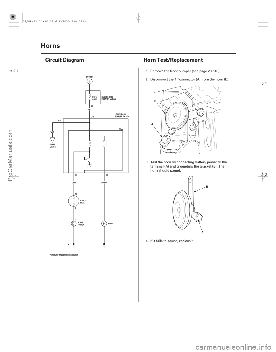
Circuit Diagram
Horn Test/Replacement
F31 G16
G7
Q3
HORN
* : Ground through steering column. * MICU
ORN LT GRN (15 A) No. 12
WHT
WHT BATTERY
UNDER-DASH
FUSE/RELAY BOX
BRAKE
LIGHTS
CABLE
REEL
HORN
SWITCH UNDER-HOOD
FUSE/RELAY BOX
D8
10 3
11A B
AB
1. Remove the front bumper (see page 20-146).
2. Disconnect the 1P connector (A) from the horn (B).
3. Test the horn by connecting battery power to the
terminal (A) and grounding the bracket (B). The
horn should sound.
4. If it fails to sound, replace it.
08/08/21 14:26:09 61SNR030_220_0148
ProCarManuals.com
DYNOMITE -2009-
Page 2098 of 2893
������(�#�'�����!���������
�����
�����������������)�
��
�´
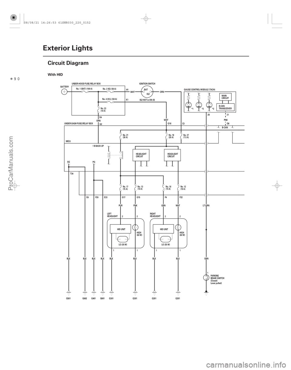
With HID
22-150Exterior Lights
Circuit Diagram
BATTERY
No. 1 (BAT) (100 A)
UNDER-HOOD FUSE/RELAY BOX
No. 4 (H/L) (50 A)
ORN No. 2 (IG) (50 A)
WHT
IGNITION SWITCH
BATIG2
WHT
ORN
IG2 HOT in ON (II)
G18 28 21
Q6
PNK
GAUGE CONTROL MODULE (TACH)
*1 *2 *3
LT GRNORN B-CAN
T34
G501 BLK
LO (35 W)
HID UNIT HID UNIT
LO (35 W)
G2
BLK
BLK
BLK
BLK
BLK BLK SG
E6
G602 G601 E33
F20
PG
BLK
G401 BBACKUP
MICU
G301 G201 F22
F4
G15
G17
2
2
11
1 2
1 2
G201
G301 GRN WHT
PUR
UNDER-DASH FUSE/RELAY BOX
PNK PARKING
BRAKE SWITCH
(Closed:
Lever pulled)B-CAN
TRANSCEIVER
MAIN
CIRCUIT
LEFT
HEADLIGHT RIGHT
HEADLIGHT
H1
K1
D4 C3
1
HEADLIGHT
CIRCUIT
HEADLIGHT
CIRCUIT
No. 37
(7.5 A)
No. 18
(20 A)
No. 21
(30 A)
No. 23
(10 A)
No. 17
(15 A)No. 13
(10 A) No. 16
(15 A)
No. 12
(10 A)
HIGH
(60 W) HIGH
(60 W)
08/08/21 14:26:53 61SNR030_220_0152
ProCarManuals.com
DYNOMITE -2009-
Page 2100 of 2893
������(�#�'�����!���������
�����
�����������������)�
��
�´
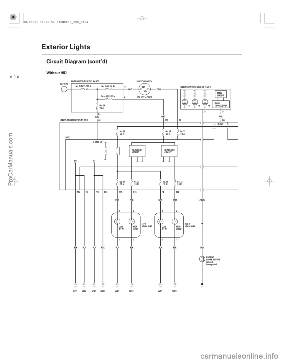
Without HID
22-152Exterior Lights
Circuit Diagram (cont’d)
G18
G501 BLKSG
T34 E6
G602BLK *3
*2
*1
IG2 HOT in ON (II) GAUGE CONTROL MODULE (TACH)
B-CANPNK
Q6 21
28
ORN
LT GRN
ORN
WHT
IG2
BAT
IGNITION SWITCH
No. 2 (IG) (50 A)
G2
BLK
BLK
BLK
BLK
BLK WHT
G601 E33
F20
PG
BLK
G401 BBACKUP
MICU ORNNo. 4 (H/L) (50 A)
G301 G201 F22
F4
G15
G17
2
2
11
1 2
1
2
G201
G301 GRN WHT
PUR
UNDER-DASH FUSE/RELAY BOX
UNDER-HOOD FUSE/RELAY BOX
PNK
No. 1 (BAT) (100 A)
BATTERY
RIGHT
HEADLIGHT
LEFT
HEADLIGHT MAIN
CIRCUIT
B-CAN
TRANSCEIVER
PARKING
BRAKE SWITCH
(Closed:
Lever pulled)
H1
K1
D4
1
C3
HEADLIGHT
CIRCUIT HEADLIGHT
CIRCUIT
No. 23
(10 A)
No. 21
(20 A) No. 18
(20 A)No. 37
(7.5 A)
No. 17
(10 A) No. 13
(10 A) No. 16
(10 A)No. 12
(10 A)
LOW
(51 W) HIGH
(60 W)
LOW
(51 W)HIGH
(60 W)
08/08/21 14:26:54 61SNR030_220_0154
ProCarManuals.com
DYNOMITE -2009-
Page 2102 of 2893
����
�(�#�'���������������
�����
�����������������)����
�´
�µ
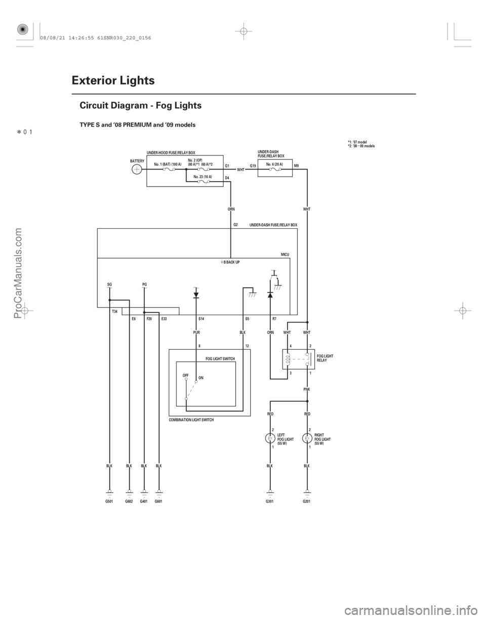
TYPE S and ’08 PREMIUM and ’09 models
22-154Exterior Lights
Circuit Diagram - Fog Lights
E33
BLK
BLK PG
F20
E6
T34
SG
BLK BLK BBACKUP
ORN
No. 23 (10 A)
WHT
No. 6 (20 A)
WHT
1 2
BLK
BLK 2
1
RED
RED PNK
1
3 2
4 WHT
WHT
R7
ORN
BLK
PUR
COMBINATION LIGHT SWITCH 12
8
OFF
BATTERY
No. 1 (BAT) (100 A)
UNDER-HOOD FUSE/RELAY BOX
MICU
UNDER-DASH FUSE/RELAY BOX
S5
S14
FOG LIGHT SWITCH
LEFT
FOG LIGHT
(55 W)RIGHT
FOG LIGHT
(55 W)
UNDER-DASH
FUSE/RELAY BOX
FOG LIGHT
RELAY
G1
D4
G19
M9
G2
G601
G401
G602
G501 G201
G301
ON
No. 2 (OP)
(80 A)*1 (60 A)*2
*1: ’07 model
*2: ’08 09 models
08/08/21 14:26:55 61SNR030_220_0156
ProCarManuals.com
DYNOMITE -2009-