Page 2167 of 2893
����
Motor Test
Pulser Test
22-217
Driver’s Power Window Motor Test
Terminal
Direction 14
UP
DOWN
1. Remove the door pane")
�´�µ
�´�µ
�´�µ
���
����
�(�#�'���������������������������
���
�������)����
Motor Test
Pulser Test
22-217
Driver’s Power Window Motor Test
Terminal
Direction 14
UP
DOWN
1. Remove the door panel (see page 20-7).
2. Disconnect the 6P connector from the driver’s power window motor.
3. Test the motor in each direction by connecting battery power and ground according to the table.
When the motor stops running, disconnect one
lead immediately.
4. If the motor does not run or fails to run smoothly, replace it. 5. Reconnect the 6P connector to the driver’s power
window motor.
6. Turn the ignition switch to ON (II).
7. Measure the voltage between the terminals. There should be battery voltage betweenterminals No. 6 ( ) and No. 5 ( ).
Connect an analog voltmeter between terminals No. 3 ( ) and No. 5 ( ), and run the power
window motor down or up. The voltmeter needle
should move back and forth alternately between
0 V and about 5 V (a digital voltmeter reads about
2.5 V).
Connect an analog voltmeter between terminals No. 2 ( ) and No. 5 ( ), and run the power
window motor down or up. The voltmeter needle
should move back and forth alternately between
0 V and about 5 V (a digital voltmeter reads about
2.5 V).
8. If the voltage is not as specified, do the power window master switch input test at the appropriate
terminals:No.5,6,7,and16(seepage22-214).
9. If the switch is OK, replace the power window motor.
10. Reset the power window control unit (see page 22-210).
08/08/21 14:28:40 61SNR030_220_0219
ProCarManuals.com
DYNOMITE -2009-
Page 2168 of 2893
���
��������
�(�#�'���������������������������
�����������)����
�¦�§ �¦�§
�¦�§
Front passenger’s
Rear
22-218 Power Windows
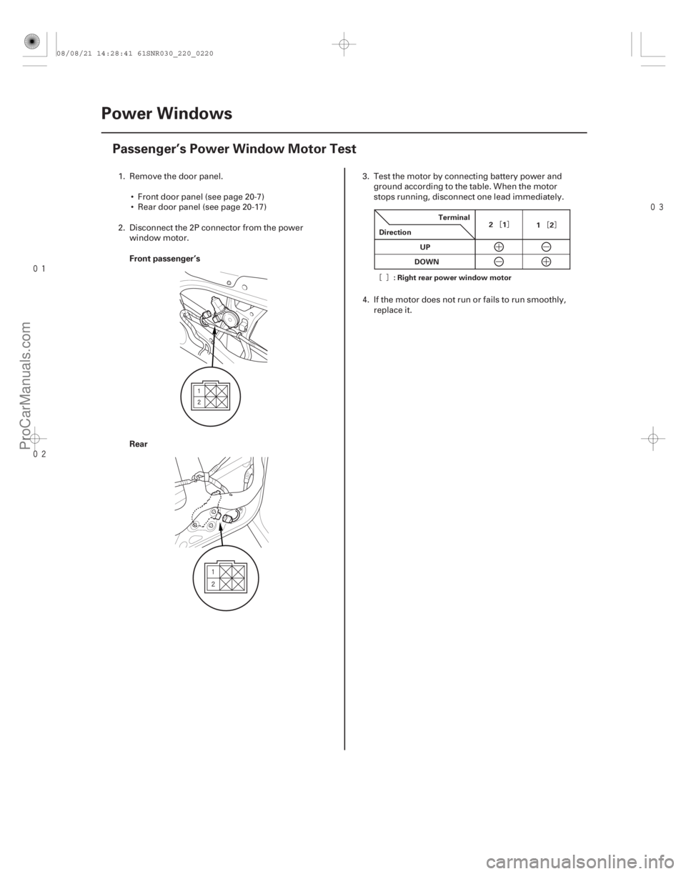
Passenger’s Power Window Motor Test
Terminal
Direction 21
12
UP
DOWN
: Right rear power window motor
1. Remove the door panel.
Front door panel (see page 20-7)
Rear door panel (see page 20-17)
2. Disconnect the 2P connector from the power window motor. 3. Test the motor by connecting battery power and
ground according to the table. When the motor
stops running, disconnect one lead immediately.
4. If the motor does not run or fails to run smoothly, replace it.
08/08/21 14:28:41 61SNR030_220_0220
ProCarManuals.com
DYNOMITE -2009-
Page 2170 of 2893
���
��������
����
�(�#�'���������������������������
�����������)���
Front passenger’s
Rear
22-220
Power Windows
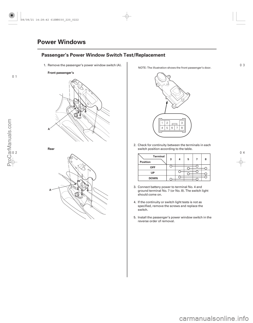
Passenger’s Power Window Switch Test/Replacement
A
A Terminal
Position 34578
OFF UP
DOWN
1. Remove the passenger’s power window switch (A).
2. Check for continuity between the terminals in eachswitch position according to the table.
3. Connect battery power to terminal No. 4 and ground terminal No. 7 (or No. 8). The switch light
should come on.
4. If the continuity or switch light tests is not as specified, remove the screws and replace the
switch.
5. Install the passenger’s power window switch in the reverse order of removal.NOTE: The illustration shows the front passenger’s door.
08/08/21 14:28:42 61SNR030_220_0222
ProCarManuals.com
DYNOMITE -2009-
Page 2173 of 2893
����
�(�#�'���������������������������������������)����
22-223
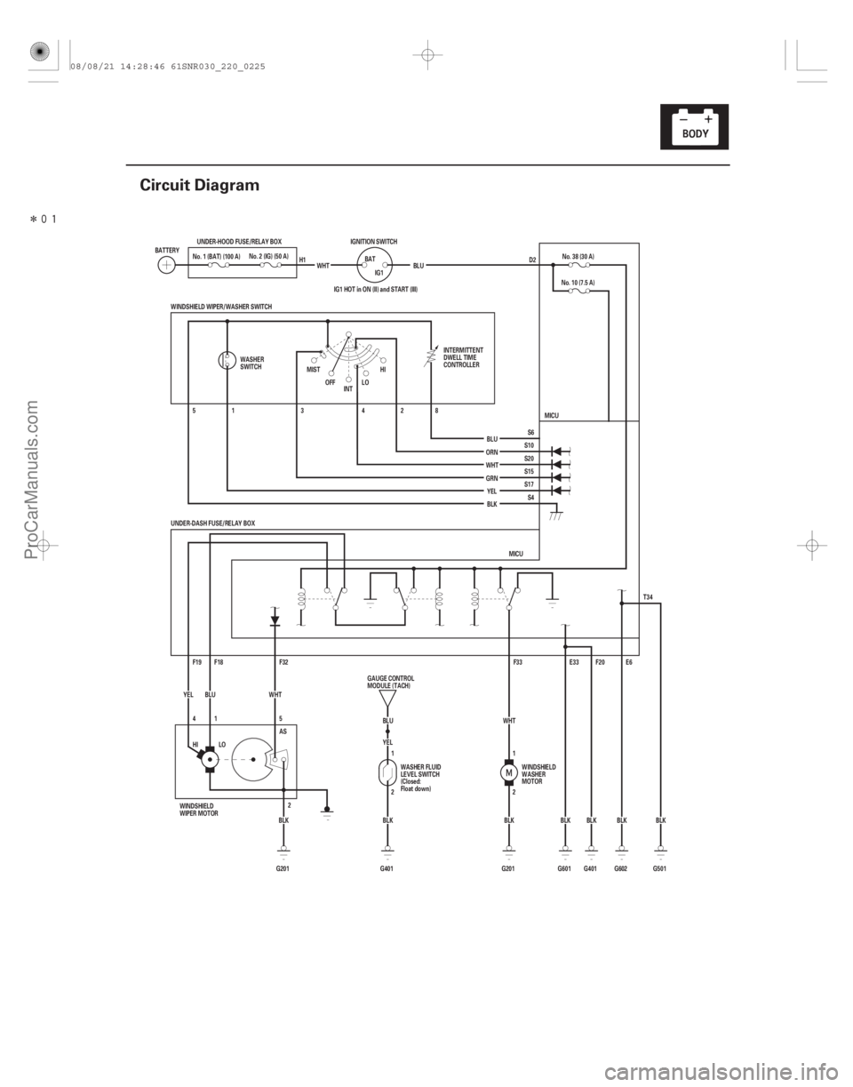
Circuit Diagram
D2
BLK
G401 F20
G601 BLK E33
HI LO BLK
G201 AS
2 E6
BLK
G602
IG1 HOT in ON (II) and START (III)
BLU
G401 BLK YEL
2 1 T34
G501BLK
UNDER-DASH FUSE/RELAY BOX
MICU
F33
F32
F19 F18 8
2
4
3
1
5
5
41 WHT
YEL BLU
WINDSHIELD WIPER/WASHER SWITCH
MICU
S4
S17 S15
S20 S10 S6
ORN
WHT GRN
YEL
BLU No. 10 (7.5 A)
No. 38 (30 A)
WHT
BLK
HI
LO
MIST
INT
OFF
BATTERY
No. 2 (IG) (50 A)
UNDER-HOOD FUSE/RELAY BOX
WHTIGNITION SWITCH
BATIG1 BLU
BLK
G201 1
2
No. 1 (BAT) (100 A)
WASHER
SWITCH INTERMITTENT
DWELL TIME
CONTROLLER
WINDSHIELD
WASHER
MOTOR
WASHER FLUID
LEVEL SWITCH
(Closed:
Float down)
GAUGE CONTROL
MODULE (TACH)
WINDSHIELD
WIPER MOTOR H1
08/08/21 14:28:46 61SNR030_220_0225
ProCarManuals.com
DYNOMITE -2009-
Page 2175 of 2893
 UNDER-DASH FUSE/RELAY BOX CONNECTOR F (34P)
LOW (BLU) HI")
��������
����
�µ
�µ
�µ
�µ
�µ
�µ �µ
�µ
�µ
�µ
YES
NO
YES
NO
YES
NO
YES
NO
YES
NO
22-225
WINDSHIELD WIPER MOTOR 5P CONNECTOR
AS (WHT) UNDER-DASH FUSE/RELAY BOX CONNECTOR F (34P)
LOW (BLU) HIGH (YEL)
WINDSHIELD WIPER MOTOR 5P CONNECTOR GND (BLK)
10. Turn the ignition switch to ON (II).
11. Measure the voltage between windshield wipermotor 5P connector terminal No. 5 and body
ground.
Repair a short to power in the WHT wire.
Faulty MICU; replace the under-dash fuse/
relay box.
12. Turn the ignition switch to LOCK (0).
13. Check the No. 38 (30 A) fuse in the under-dash fuse/ relay box.
Go to step 14.
Replace the fuse and recheck the system.
14. Do the wiper motor test (see page 22-231).
Go to step 15.
Replace the windshield wiper motor
(see page 22-233) and recheck.
15. Reconnect the windshield wiper motor 5P connector. 16. Measure the voltage between under-dash fuse/
relay box connector F (34P) terminals No. 18 (LOW)
and No. 19 (HIGH) and body ground with the wiper
switch in corresponding position.
Go to step 17.
Faulty MICU; replace the under-dash fuse/
relay box (see page 22-66).
17. Measure the voltage between windshield wiper motor 5P connector terminal No. 2 and body
ground.
Repair an open in the BLU (LOW) or YEL
(HIGH) wire.
Repair an open in the BLK wire or poor
ground (G 201).
Wire side of female terminals Wire side of female terminals
Wire side of female terminals
Is there voltage? IsthefuseOK?Does t he w i per mot or r un nor mal l y ? Is there battery voltage?
Is t her e l ess t han 0.5 V ?
08/08/21 14:28:46 61SNR030_220_0227
ProCarManuals.com
DYNOMITE -2009-
Page 2179 of 2893

Cavity Wire Test conditionTest: Desired result Possible cause if desired result
is not obtained
22-229
3. Inspect the connector and socket terminals to be sure they are all making good contact.
If the terminals are bent, loose or corroded, repair them as necessary and recheck the system.
IftheterminalslookOK,gotostep4.
4. With the connectors still disconnected, do these input tests at the following connectors. If any test indicates a problem, find and correct the cause, then recheck the system.
If all the input tests prove OK, go to step 5.
F18 BLU Under all conditions Connect battery power to terminal
F18:
The windshield wiper motor
should run at low speed.Poor ground (G201)
Faulty windshield wiper
motor
An open in the wire
F19 YEL Under all conditions Connect battery power to terminal F19:
The windshield wiper motor
should run at high speed.Poor ground (G201)
Faulty windshield wiper
motor
An open in the wire
F32 WHT Disconnect the windshield wiper
motor 5P connector Check for continuity between
terminal F32 and wiper motor 5P
connector terminal No. 5:
There should be continuity. An open in the wire
F33 WHT Under all conditions Connect battery power to terminal F33:
The windshield washer motor
should run.Poor ground (G201)
Faulty windshield washer
motor
An open in the wire
S6 ·
S4 BLU
·
BLK Windshield wiper/
washer switch
(intermittent dwell
timer) turned Measure the resistance between
terminals S6 and S4:
There resistance should vary from
about 0 to 1 k . Faulty windshield wiper/
washer switch
An open in the wire
A short to ground in the wire
(cont’d)
08/08/21 14:28:48 61SNR030_220_0231
ProCarManuals.com
DYNOMITE -2009-
Page 2181 of 2893
���� �´�µ���
����
�(�#��������������������������������
�������)���
22-23122-231
Wiper/Washer Switch Test Wiper Motor Test
A
B
OFF INT
LO
HI")
���
�����(�#�'�������������������������������
�������)���� �´�µ���
����
�(�#�'�������������������������������
�������)���
22-23122-231
Wiper/Washer Switch Test Wiper Motor Test
A
B
OFF INT
LO
HI Terminal
Position
Mist ON
Washer ON 1
2
345 8
Intermittent dwell
timer turned A
B
Terminal
Position
LOW SPEED
HIGH SPEED 1
2 3
1. Remove the wiper/washer switch (see page 22-234).
2. Disconnect the dashboard wire harness 8P
connector (A) from the wiper/washer switch (B).
3. Check for continuity between the terminals in each switch position according to the table.
4. If the continuity is not as specified, replace the switch. 1. Remove the wiper arms (see page 22-233).
NOTE: Carefully remove the wiper arms so that
they do not touch the hood.
2. Remove the hood seal and cowl cover.
3. Disconnect the 5P connector (A) from the wiper motor (B).
4. Test the motor by connecting battery power and ground according to the table. If the motor does not
run or fails to run smoothly, replace the motor.
5. Connect the battery power to terminal No. 1, and body ground to terminal No. 2 of the 5P connector.
Then connect an analog voltmeter between
terminal No. 1 ( ) and terminal No. 5 ( ). When
the park switch makes contact, the pointer should
swing. If not, replace the motor.
08/08/21 14:28:48 61SNR030_220_0233
ProCarManuals.com
DYNOMITE -2009-
Page 2182 of 2893
���� ���
�(�#������������������������������
�
�������)���
22-23222-232 Wipers/Washers
Washer Motor Test
Washer Fluid Level Switch Test
A
B A
B
1")
����
�(�#�'�������������������������������
�������)���� ���
�(�#�'�����������������������������
�
�������)���
22-23222-232 Wipers/Washers
Washer Motor Test
Washer Fluid Level Switch Test
A
B A
B
1. Remove the right inner fender (see page 20-171).
2. Disconnect the 2P connector (A) from the washermotor (B).
3. Test the motor by connecting battery power to terminal No. 1 and ground terminal No. 2 of the
washer motor. The motor should run.
If the motor does not run, or fails to run smoothly, replace it.
If the motor runs smoothly, but little or no washer fluid is pumped, check for a disconnected
or blocked washer hose, or a clogged washer
motor outlet. 1. Remove the right inner fender (see page 20-171).
2. Disconnect the 2P connector (A) from the washer
fluid level switch (B).
3. Remove the washer fluid level switch from the washer reservoir.
NOTE: Fluid may flow out of the opening.
4. Check for continuity between terminals No. 1 and No. 2 in each float position.
There should be continuity when the float is down.
There should be no continuity when the float is up.
5. If the continuity is not as specified, replace the switch.
Terminal side of
male terminals
08/08/21 14:28:49 61SNR030_220_0234
ProCarManuals.com
DYNOMITE -2009-