Page 251 of 2893
����
Engine Mechanical
Engine Lubrication
................................................................................................................")
�(�#�'�������������������������������
�/�����)����
Engine Mechanical
Engine Lubrication
...................................................................................................................................... ..............
.......................................... .........................................
............................................. ..............................
.......................................................... ................................................................................................................
..............................................
....................................................
......................................................... ......................................................
................................................................
...................................................................... ..............
.......................................... .........................................
............................................. ..............................
.......................................................... ................................................................................................................
..............................................
....................................................
......................................................... ......................................................
Special Tools . 8-2
Component Location Index . 8-3
Symptom Troubleshooting Index . 8-5
Low Oil Pressure Indicator Circuit Diagram . 8-6
Low Oil Pressure Indicator Circuit
Troubleshooting (Open) . 8-7
Low Oil Pressure Indicator Circuit Troubleshooting (Short) . 8-8
Oil Pressure Switch Test . 8-9
Oil Pressure Switch Replacement . 8-9
Oil Pressure Test . 8-10
Engine Oil Replacement . 8-10
Engine Oil Filter Replacement . 8-11
Oil Filter Feed Pipe Replacement . 8-12
Oil Cooler Replacement . 8-13
Oil Jet Replacement . 8-13
Oil Jet Inspection . 8-14
Oil Pump Overhaul . 8-15
08/08/21 14:36:35 61SNR030_080_0001
ProCarManuals.com
DYNOMITE -2009-
Page 252 of 2893
���
�(�#�'�������������������������������
�%�����)����Ref. No. Tool Number Description Qty
8-2
Engine Lubrication
Special Tools
07HAA-PJ70101
Oil Filter Wrench 1
08/08/21 14:36:35 61SNR030_080_0002
ProCarManuals.com
DYNOMITE -2009-
Page 253 of 2893
����
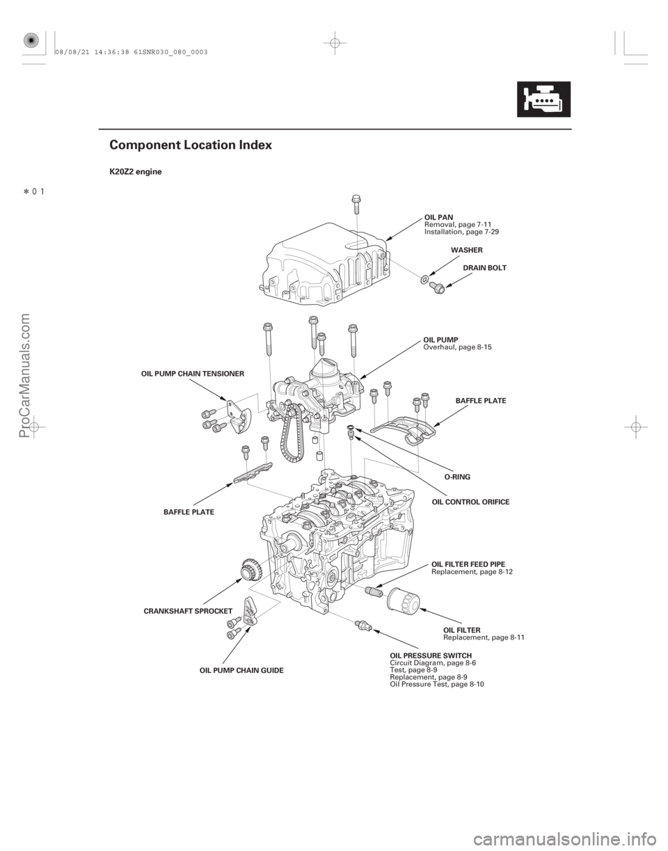
�(�#�'���������������������������������������)���� K20Z2 engine
8-3
Component Location Index
OIL PRESSURE SWITCHOIL FILTER
OIL PUMP
DRAIN BOLT
O-RING
OIL PAN
BAFFLE PLATE
OIL CONTROL ORIFICE
OIL PUMP CHAIN GUIDE
CRANKSHAFT SPROCKET
OIL PUMP CHAIN TENSIONER
BAFFLE PLATE OIL FILTER FEED PIPEWASHER
Circuit Diagram, page 8-6
Test, page 8-9
Replacement, page 8-9
Oil Pressure Test, page 8-10 Replacement, page 8-11
Overhaul, page 8-15
Removal, page 7-11
Installation, page 7-29
Replacement, page 8-12
08/08/21 14:36:38 61SNR030_080_0003
ProCarManuals.com
DYNOMITE -2009-
Page 254 of 2893
����
�(�#�'���������������������������������������)���
K20Z3 engine
8-4Engine Lubrication
Component Location Index (cont’d)
OIL PRESSURE SWITCH
OIL FILTER
OIL PUMP
DRAIN BOLT
O-RING OIL PAN
BAFFLE PLATE
OIL CONTROL ORIFICE
OIL PUMP CHAIN GUIDE
CRANKSHAFT SPROCKET OIL PUMP CHAIN TENSIONER
BAFFLE PLATE
OIL COOLERWASHER
OIL COOLER CENTER BOLT OIL JETS
Circuit Diagram, page 8-6
Test, page 8-9
Replacement, page 8-9
Oil Pressure Test, page 8-10 Replacement, page 8-11
Overhaul, page 8-15
Removal, page 7-11
Installation, page 7-29
Replacement, page 8-13 Inspection, page 8-14
08/08/21 14:36:41 61SNR030_080_0004
ProCarManuals.com
DYNOMITE -2009-
Page 255 of 2893
���
Symptom Diagnostic procedure Also check for
8-5
Symptom Troubleshooting Index
Excessive engine oil
consumption
1.
2.
3.
4.
5.Verify that the engine oi")
�(�#�'���������������������������������������)���
Symptom Diagnostic procedure Also check for
8-5
Symptom Troubleshooting Index
Excessive engine oil
consumption
1.
2.
3.
4.
5.Verify that the engine oil filler cap, the oil drain
bolt, and the oil filter are tight.
Check for oil leaks.
Check for worn valve guide(s) (see page 6-55) or
worn valve stem seal(s) (see page 6-54).
Check for damaged or worn piston ring(s)
(see page 7-21).
Check for damaged or worn engine internal parts
(cylinder wall, pistons, etc.) (see page 7-16).
Low oil pressure indicator does
not come on with the ignition
switch in ON (II) 1.
2.Do the low oil pressure indicator circuit
troubleshooting (Open) (see page 8-7).
Test the oil pressure switch (see page 8-9). An open in the wire
between the engine
control module (ECM)/
powertrain control
module (PCM) and the
oil pressure switch
Low oil pressure indicator stays
on 1.
2.
3.
4.
5.
6.
7.
8.Check the engine oil level.
Do the low oil pressure indicator circuit
troubleshooting (Short) (see page 8-8).
Test the oil pressure switch (see page 8-9).
Check the engine oil pressure (see page 8-10).
Check the oil filter for clogging.
Check the oil screen for clogging.
Check the relief valve (see page 8-15).
Testtheoilpump(seepage8-17). A wire shorted to
ground between the
ECM/PCM and the oil
pressure switch
08/08/21 14:36:41 61SNR030_080_0005
ProCarManuals.com
DYNOMITE -2009-
Page 256 of 2893
����
�(�#�'�������������������������������
�������)����
8-6Engine Lubrication
Low Oil Pressure Indicator Circuit Diagram
D2
Q9
H1
191
17
36
B7
CANL
CANH DRIVERBRN
12 V
5V GAUGE CONTROL MODULE (TACH)
IGNITION SWITCH
BATIG1
ECM/PCM
OPSW
A37
A36 RED
WHT CPU
No. 2 (50 A)
No. 10
(7.5 A)
BATTERY
UNDER-HOOD FUSE/RELAY BOX
No. 1 (100 A)
YEL/REDUNDER-DASH
FUSE/RELAY BOX
LOW OIL
PRESSURE
INDICATOR
OIL PRESSURE SWITCH
(Closed: Lost pressure)
IG1 HOT in ON (II)
and START (III)
1
WHT BLU
CANH
CANL
08/08/21 14:36:41 61SNR030_080_0006
ProCarManuals.com
DYNOMITE -2009-
Page 257 of 2893
����
�µ
�µ
�µ
�µ �µ
�µ
YES
NO
YES
NO YES
NO
8-7
Low Oil Pressure Indicator Circuit Troubleshooting (Open)
ECM/PCM CONNECTOR B (44P)
OPSW
(YE")
����
�(�#�'���������������������������������������)����
�µ
�µ
�µ
�µ �µ
�µ
YES
NO
YES
NO YES
NO
8-7
Low Oil Pressure Indicator Circuit Troubleshooting (Open)
ECM/PCM CONNECTOR B (44P)
OPSW
(YEL/RED)
OIL PRESSURE
SWITCH CONNECTOR
OPSW
(YEL/RED)
1. Connect the Honda Diagnostic System (HDS) to thedata link connector (DLC) (see step 2 on page 11-3).
2. Turn the ignition switch to ON (II).
3. Make sure the HDS communicates with the vehicle and the engine control module (ECM)/powertrain
control module (PCM). If it does not communicate,
troubleshoot the DLC circuit (see page 11- 204).
4. Check for DTCs (see page 11-3). If a DTC is present, diagnose, and repair the cause before continuing
with this test.
5. Check the OIL PRESSURE SWITCH in the PGM-FI DATA LIST with the HDS.
Replace the gauge control module (tach)
(see page 22-277).
Go to step 6.
6. Turn the ignition switch to LOCK (0).
7. Check the oil pressure switch (see page 8-9).
Go to step 8.
Replace the oil pressure switch (see page 8-9).
8. Turn the ignition switch to ON (II), and jump the SCS line with the HDS, then turn the ignition switch
to LOCK (0).
NOTE: This step must be done to protect the ECM/
PCM from damage.
9. Disconnect ECM/PCM connector B (44P) and the oil pressure switch connector. 10. Check for continuity between ECM/PCM connector
terminal B7 and the oil pressure switch connector.
Update the ECM/PCM if it does not have the
latest software (see page 11-227), or substitute a
known-good ECM/PCM (see page 11-7), then
recheck. If the symptom/indication goes away with
a known-good ECM/PCM, replace the original
ECM/PCM (see page 11-228).
Repair an open in the wire between the oil
pressure switch and ECM/PCM connector terminal
B7.
Terminal side of female terminals
Wire side of
female terminal
Is ON indicated?
I s t he oi l pr essur e sw i t ch OK ? Is there continuity?
08/08/21 14:36:41 61SNR030_080_0007
ProCarManuals.com
DYNOMITE -2009-
Page 258 of 2893
���
�µ
�µ
�µ
�µ
�µ
�µ �µ
�µ
YES
NO
YES
NO
YES
NO YES
NO
8-8Engine Lubrication
Low Oil Pressure Indicator Circuit Troubleshooting (Short)")
�����
�(�#�'���������������������������������������)���
�µ
�µ
�µ
�µ
�µ
�µ �µ
�µ
YES
NO
YES
NO
YES
NO YES
NO
8-8Engine Lubrication
Low Oil Pressure Indicator Circuit Troubleshooting (Short)
OIL PRESSURE SWITCH CONNECTOR
OPSW
(YEL/RED)
1. Connect the Honda Diagnostic System (HDS) to thedata link connector (DLC) (see step 2 on page 11-3).
2. Turn the ignition switch to ON (II).
3. Make sure the HDS communicates with the vehicle and the engine control module (ECM)/powertrain
control module (PCM). If it does not communicate,
troubleshoot the DLC circuit (see page 11- 204).
4. Check for DTCs (see page 11-3). If a DTC is present, diagnose, and repair the cause before continuing
with this test.
5. Start the engine, and check the OIL PRESSURE SWITCH in the PGM-FI DATA LIST with the HDS.
Replace the gauge control module (tach)
(see page 22-277).
Go to step 6.
6. Turn the ignition switch to LOCK (0).
7. Disconnect the oil pressure switch connector.
8. Start the engine, and check the OIL PRESSURE SWITCH in the PGM-FI DATA LIST with the HDS.
Turn the ignition switch to LOCK (0), then go
to step 9.
Turn the ignition switch to LOCK (0), then go
to step 10.
9. Check the oil pressure switch (see page 8-9).
Do the oil pressure test (see page 8-10).
Replace the oil pressure switch (see page 8-9). 10. Turn the ignition switch to ON (II), and jump the
SCS line with the HDS, then turn the ignition switch
to LOCK (0).
NOTE: This step must be done to protect the ECM/
PCMfromdamage.
11. Disconnect ECM/PCM connector B (44P).
12. Check for continuity between the oil pressure switch connector and body ground.
Repair a short to ground in the wire between
the oil pressure switch and ECM/PCM connector
terminal B7.
Update the ECM/PCM if it does not have the
latest software (see page 11-227), or substitute a
known-good ECM/PCM (see page 11-7), then
recheck. If the symptom/indication goes away with
a known-good ECM/PCM, replace the original
ECM/PCM (see page 11-228).
Wire side of female terminal
I s OF F i nd i cat ed ?
I s OF F i nd i cat ed ?I s t he oi l pr essur e sw i t ch OK ? Is there continuity?
08/08/21 14:36:42 61SNR030_080_0008
ProCarManuals.com
DYNOMITE -2009-