Page 56 of 2893

��������
���
�(�#�'�����������������������
�������
�������)����
�µ
�µ
YES
NO
M/T model
4-84-8 Starting System
Starter System Circuit
Troubleshooting (cont’d)
Clutch Interlock Switch Test
OTC3131 A
B
Terminal
Position
Clutch Interlock Switch
Clutch Interlock Switch 2
1
(PRESSED)
(RELEASED)
12. Do the STARTING TEST with the alternator, regulator battery & starter tester.
NOTE: The probe is used for starter testing.
Go to step 13.
Replace the starter, or remove and
disassemble it, and check for these problems:
Draginthestarterarmature
Short in the armature winding
Excessive drag in the engine
Open circuit in starter armature commutator segments
Excessively worn starter brushes
Open circuit in the starter brushes
Dirty or damaged helical splines or drive gear
Faulty overrunning clutch
13. Remove the starter, and inspect its drive gear and the flywheel ring gear (M/T model) or the torque
converter ring gear (A/T model) for damage.
Replace any damaged parts.
14. Select ECM/PCM reset (see page 11-4) in the PGM- FI INSPECTION menu to cancel ALL INJECTORS
STOP with the HDS. 1. Disconnect the clutch interlock switch 2P connector
(A).
2. Remove the clutch interlock switch (B).
3. Check for continuity between the terminals accordingtothetable.
If the continuity is not as specified, replace the clutch interlock switch (see page 12-8).
If OK, install the clutch interlock switch, and adjust the pedal height (see page 12-8).
Terminal side of
male terminals
Does the display indicate cranking voltage greatert han or equal t o 8.5 V and t he cur r ent d r aw l esst han or equal t o 380 A?
08/08/21 14:09:23 61SNR030_040_0009
ProCarManuals.com
DYNOMITE -2009-
Page 65 of 2893

�Ì
�Ì
�
��
�
��
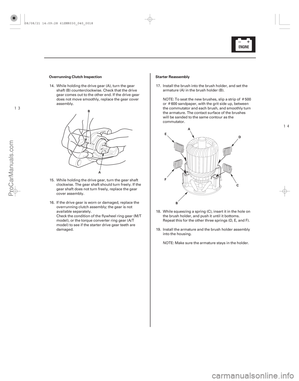
Overrunning Clutch Inspection Starter Reassembly
4-17
B
A A
B CD
E
F
14. While holding the drive gear (A), turn the gear shaft (B) counterclockwise. Check that the drive
gear comes out to the other end. If the drive gear
does not move smoothly, replace the gear cover
assembly.
15. While holding the drive gear, turn the gear shaft clockwise. The gear shaft should turn freely. If the
gear shaft does not turn freely, replace the gear
cover assembly.
16. If the drive gear is worn or damaged, replace the overrunning clutch assembly; the gear is not
available separately.
Check the condition of the flywheel ring gear (M/T
model), or the torque converter ring gear (A/T
model) to see if the starter drive gear teeth are
damaged. 17. Install the brush into the brush holder, and set the
armature (A) in the brush holder (B).
NOTE: To seat the new brushes, slip a strip of 500
or 600 sandpaper, with the grit side up, between
the commutator and each brush, and smoothly turn
the armature. The contact surface of the brushes
will be sanded to the same contour as the
commutator.
18. While squeezing a spring (C), insert it in the hole on the brush holder, and push it until it bottoms.
Repeat this for the other three springs (D, E, and F).
19. Install the armature and the brush holder assembly into the housing.
NOTE: Make sure the armature stays in the holder.
08/08/21 14:09:28 61SNR030_040_0018
ProCarManuals.com
DYNOMITE -2009-
Page 70 of 2893
�����µ�µ
Spark Plugs
K20Z2 engine
DENSO: SKJ20DR-M11
K20Z3 engine
DENSO: SK22PR-M11S
Electrode Gap
Standard(New): 1.0 1.1 mm (0.039 0.043 in.)
4-22 Ignition System
Spark Plug Inspection (cont’d)
B
A
3. Replace the plug at the specified interval or if the
center electrode (A) is rounded, or if the spark plug
gap (B) is out of specification. Use only the listed
spark plugs.
NOTE: Do not adjust the gap of iridium tip plugs.
4. Apply a small amount of anti-seize compound to the plug threads, and screw the plugs into the
cylinder head, finger-tight. Torque them to 18 N·m
(1.8 kgf·m, 13 lbf·ft).
08/08/21 14:10:07 61SNR030_040_0023
ProCarManuals.com
DYNOMITE -2009-
Page 80 of 2893

����
�������
����
�(�#�'�����������
���
����������������� �����)����
�µ�µ �µ
Auto-tensioner Spring Torque:
32.5 39.7 N·m (3.31 4.05 kgf·m, 23.9 29.3 lbf·ft)
4-324-32 Charging System
Drive Belt Auto-tensioner
Inspection (cont’d)
Drive Belt Auto-tensioner Removal/
Installation
A
B
C
E
F
8x1.25mm
22 N·m
(2.2 kgf·m, 16 lbf·ft) 6x1.0mm
12 N·m
(1.2 kgf·m, 8.7 lbf·ft)
A
10x1.25mm
56 N·m (5.7 kgf·m, 41 lbf·ft) B
30 °
30 °
D
6. Remove the auto-tensioner (see page 4-32).
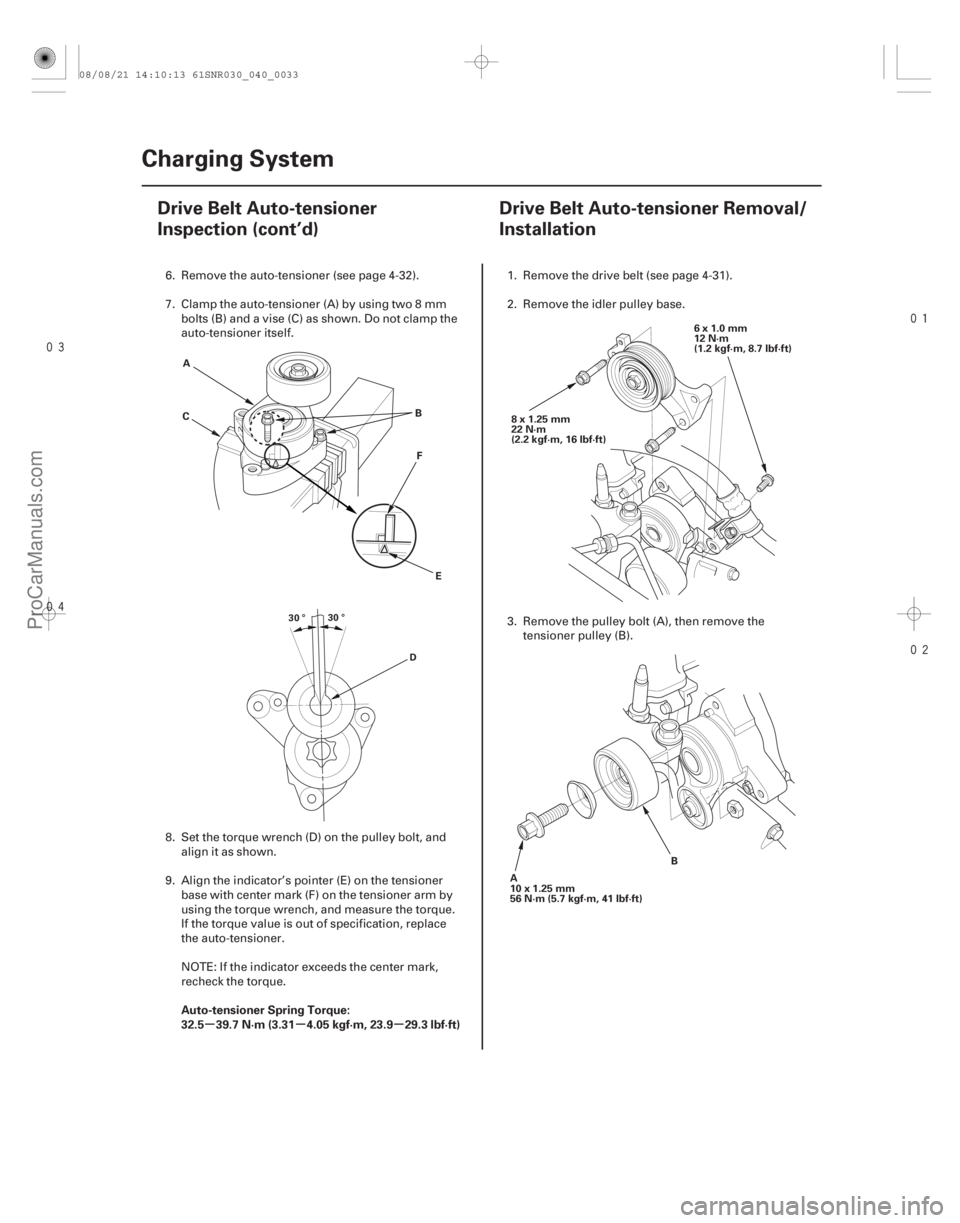
7. Clamp the auto-tensioner (A) by using two 8 mmbolts (B) and a vise (C) as shown. Do not clamp the
auto-tensioner itself.
8. Set the torque wrench (D) on the pulley bolt, and align it as shown.
9. Align the indicator’s pointer (E) on the tensioner base with center mark (F) on the tensioner arm by
using the torque wrench, and measure the torque.
If the torque value is out of specification, replace
the auto-tensioner.
NOTE: If the indicator exceeds the center mark,
recheck the torque. 1. Remove the drive belt (see page 4-31).
2. Remove the idler pulley base.
3. Remove the pulley bolt (A), then remove the
tensioner pulley (B).
08/08/21 14:10:13 61SNR030_040_0033
ProCarManuals.com
DYNOMITE -2009-
Page 81 of 2893

����
�������
����
�(�#�'�����������
���
����������������� �����)����
�µ�µ �µ
Auto-tensioner Spring Torque:
32.5 39.7 N·m (3.31 4.05 kgf·m, 23.9 29.3 lbf·ft)
4-324-32 Charging System
Drive Belt Auto-tensioner
Inspection (cont’d)
Drive Belt Auto-tensioner Removal/
Installation
A
B
C
E
F
8x1.25mm
22 N·m
(2.2 kgf·m, 16 lbf·ft) 6x1.0mm
12 N·m
(1.2 kgf·m, 8.7 lbf·ft)
A
10x1.25mm
56 N·m (5.7 kgf·m, 41 lbf·ft) B
30 °
30 °
D
6. Remove the auto-tensioner (see page 4-32).
7. Clamp the auto-tensioner (A) by using two 8 mmbolts (B) and a vise (C) as shown. Do not clamp the
auto-tensioner itself.
8. Set the torque wrench (D) on the pulley bolt, and align it as shown.
9. Align the indicator’s pointer (E) on the tensioner base with center mark (F) on the tensioner arm by
using the torque wrench, and measure the torque.
If the torque value is out of specification, replace
the auto-tensioner.
NOTE: If the indicator exceeds the center mark,
recheck the torque. 1. Remove the drive belt (see page 4-31).
2. Remove the idler pulley base.
3. Remove the pulley bolt (A), then remove the
tensioner pulley (B).
08/08/21 14:10:13 61SNR030_040_0033
ProCarManuals.com
DYNOMITE -2009-
Page 100 of 2893

�(�#�'�������������������������������
�/�����)����
Engine Mechanical
Engine Assembly
................................................................................................................................................................................. ..........................................................
...............................
............................... .................
.............................
................................................................
................................................................................................................. ..........................................................
...............................
............................... .................
.............................
Special Tools . 5-2
Engine Removal . 5-3
Engine Installation . 5-13
Side Engine Mount Replacement . 5-24
Transmission Mount Replacement . 5-29
Lower Torque Rod Replacement . 5-32
Upper Torque Rod Replacement . 5-34
Side Engine Mount Bracket Replacement . 5-35
Front Engine Mount Replacement . 5-40
08/08/21 14:20:21 61SNR030_050_0001
ProCarManuals.com
DYNOMITE -2009-
Page 107 of 2893
��������
����
M/T model
A/T model
5-8 Engine Assembly
Engine Removal (cont’d)
VSB02C000025
B
C
D
A
AAR-T1256
47. Install the front leg assembly (A), the hook (B), and
the wing nut (C) to an A and Reds engine support
hanger (AAR-T1256) onto the 2006 civic engine
hanger (VSB02C000025). Carefully position the
engine hanger on the vehicle, and attach the hook
to the forward hole in the engine hanger adapter
(D). Tighten the wing nut by hand to lift and support
the engine/transmission.
NOTE: Be careful when working around the
windshield.
48. Raise the vehicle on the lift. 49. Remove the lower torque rod.
Replace.
Replace.
Replace.
Replace.
08/08/21 14:20:25 61SNR030_050_0008
ProCarManuals.com
DYNOMITE -2009-
Page 112 of 2893
�Ì
�Ï
���
�(�#�'�����������
��������������������� �����)���� Special Tools RequiredK20Z2 engine
5-13
Engine Installation
SIDE ENGINE MOUNT BRACKET
10 x 1.25 mm
44 N·m
(4.5 kgf·m, 33 lbf·ft)
LOWER TORQUE ROD BRACKET A/C COMPRESSOR BRACKET
12x1.25mm
74 N·m
(7.5 kgf·m, 54 lbf·ft) 10x1.25mm
44 N·m
(4.5 kgf·m, 33 lbf·ft)
Universal lifting eyelet 07AAK-SNAA120
Engine hanger adapterVSB02C000015
Engine support hanger, A and Reds AAR-T 1256
2006 Civic engine hanger VSB02C000025
Front subframe adapter VSB02C000016 : These special tools are available through Honda Canada Inc. Technical Tools Department; FAX 866- 398-8665/
e-mail: ch_technicaltools ch.honda.com
1. Install the engine mount brackets and the accessory brackets, then tighten their bolts to the specified torque.
(cont’d)
Replace.
08/08/21 14:20:28 61SNR030_050_0013
ProCarManuals.com
DYNOMITE -2009-