Page 2869 of 2893
����
Removal Installation
24-188SRS
Driver’s Airbag Replacement
A
B
A
B
C
9.8 N·m (1.0 kgf·m, 7.2 lbf·ft)
A
B
A B
NOTE: If r")
����
���� ���
�����
�(�#�'�����������������������
��������� �����)����
Removal Installation
24-188SRS
Driver’s Airbag Replacement
A
B
A
B
C
9.8 N·m (1.0 kgf·m, 7.2 lbf·ft)
A
B
A B
NOTE: If replacing the driver’s airbag after deployment,
refer to Component Replacement/Inspection After
Deployment (see page 24-185) for a complete list of
other parts that must also be replaced.
1. Do the battery terminal disconnection procedure (see page 22-68), then wait at least 3 minutes
before starting work.
2. Remove the access panel (A) from the steering wheel, then disconnect the driver’s airbag 4P
connector (B) from the cable reel.
3. Using a TORX T30 bit, remove the two TORX bolts (A) and discard them.
4. Disconnect the horn switch connector (1P), then remove the driver’s airbag (B). 1. Connect the horn switch connector (1P) (A) to the
driver’s airbag.
2. Place the driver’s airbag (B) in the steering wheel, and secure it with new TORX bolts (C).
3. Connect the driver’s airbag 4P connector (A) to the cable reel 4P connector, then install the access
panel (B) on the steering wheel.
4. Do the battery terminal reconnection procedure (see page 22-68).
5. Clear any DTCs (see page 24-23).
6. After installing the airbag, confirm proper system operation:
Turn the ignition switch to ON (II); the SRS indicator should come on for about 6 seconds
andthengooff.
Make sure the horn works.
Replace.
08/08/21 14:01:55 61SNR030_240_0188
ProCarManuals.com
DYNOMITE -2009-
Page 2877 of 2893
����
Special Tools Required
Driver’s Airbag
Front Passenger’s Airbag
Side Airbag
Side Curtain Airbag
Deploying Airbags in the")
����
����
����
�����
�(�#�'�����������������������
���������!�����)����
Special Tools Required
Driver’s Airbag
Front Passenger’s Airbag
Side Airbag
Side Curtain Airbag
Deploying Airbags in the Vehicle
24-196
SRS
Airbag and Tensioner Disposal
A
B
A
A
A
Deployment tool 07HAZ-SG00500
Before scrapping any airbags, side airbags, side curtain
airbags, seat belt tensioners, or seat belt buckle
tensioner (including those in a whole vehicle to be
scrapped), the part(s) must be deployed. If the vehicle is
still within the warranty period, the Honda District Parts
and Service Manager must give approval and/or special
instructions before deploying the part(s). Only after the
part(s) have been deployed (as the result of vehicle
collision, for example), can they be scrapped.
If the parts appear intact (not deployed), treat them with
extreme caution. Follow this procedure.
If an SRS equipped vehicle is to be entirely scrapped, its
airbags, side airbags, side curtain airbags, seat belt
tensioners, and seat belt buckle tensioner should be
deployed while still in the vehicle. These parts should
not be considered as salvageable parts and should
never be installed in another vehicle.1. Turn the ignition switch to LOCK (0), then disconnect the negative cable from the battery,
then wait at least 3 minutes before starting work.
2. Confirm that each airbag, side airbag, side curtain airbag, seat belt tensioner, or seat belt buckle
tensioner is securely mounted.
3. Confirm that the deployment tool is functioning properly by following the check procedure on the
tool label.
4. Remove the access panel (A) from the steering wheel, then disconnect the driver’s airbag 4P
connector (B) from the cable reel. 5. Remove the glove box, then disconnect the front
passenger’s airbag 4P connector (A) from the
dashboard wire harness.
6. Disconnect the side airbag 2P connector (A) from the floor wire harness.
7. Disconnect the floor wire harness 2P connector from the side curtain airbag (A).
08/08/21 14:01:58 61SNR030_240_0196
ProCarManuals.com
DYNOMITE -2009-
Page 2881 of 2893
���
����
�(�#�'�����������������������
�������
� �����)����
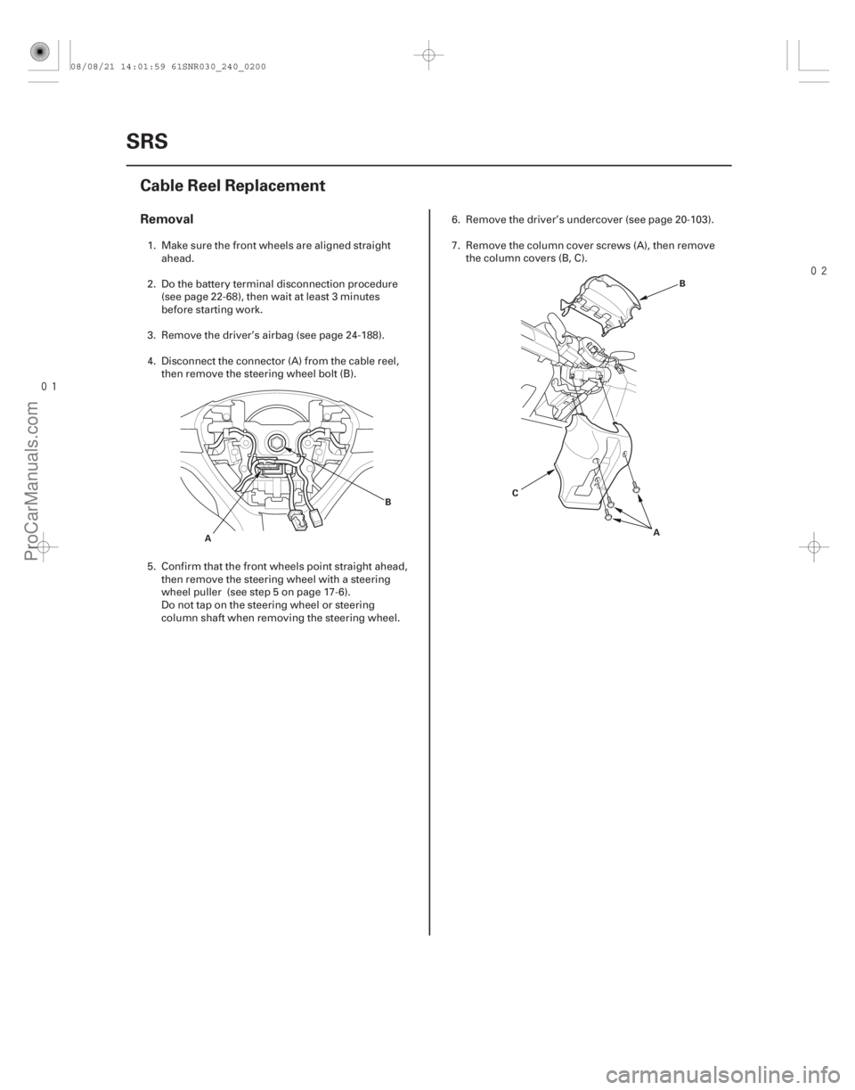
Removal
24-200 SRS
Cable Reel Replacement
A
B
AB
C
1. Make sure the front wheels are aligned straight ahead.
2. Do the battery terminal disconnection procedure (see page 22-68), then wait at least 3 minutes
before starting work.
3. Remove the driver’s airbag (see page 24-188).
4. Disconnect the connector (A) from the cable reel, then remove the steering wheel bolt (B).
5. Confirm that the front wheels point straight ahead, then remove the steering wheel with a steering
wheel puller (see step 5 on page 17-6).
Do not tap on the steering wheel or steering
column shaft when removing the steering wheel. 6. Remove the driver’s undercover (see page 20-103).
7. Remove the column cover screws (A), then remove
the column covers (B, C).
08/08/21 14:01:59 61SNR030_240_0200
ProCarManuals.com
DYNOMITE -2009-
Page 2882 of 2893
 from the cable reel 4P connector (B),
then disconnect the dashboard wire harnes")
����
�������
����
Installation
24-201
A
B
C
D
A
B
CA
B
D C
B
A
8. Disconnect the dashboard wire harness 4Pconnector (A) from the cable reel 4P connector (B),
then disconnect the dashboard wire harness 20P
connector (C) from the cable reel (D).
9. Release the lock tab (A) under the cable reel connector with a 90 ° hook shaped tool (B). Slide
the tool below the cable reel connector just above
the lock tab. Release the lower lock tab (C), and
slide the cable reel off the column. 1. Before installing the steering wheel, align the front
wheels straight ahead.
2. If not already done, disconnect the negative cable from the battery, then wait at least 3 minutes
before starting work.
3. Set the turn signal canceling sleeve (A) so that the projections (B) are aligned vertically.
4. Carefully install the cable reel (A) on the steering column shaft. Then connect 20P connector (B) to
the cable reel, and connect the 4P connector (C) to
the dashboard wire harness 4P connector (D).
(cont’d)
08/08/21 14:02:00 61SNR030_240_0201
ProCarManuals.com
DYNOMITE -2009-
Page 2883 of 2893

A
D
B
A C A
39 N·m
(4.0 kgf·m, 29 lbf·ft)
5. Install the steering column covers.
6. If necessary, center the cable reel (new
replacement ca")
����
�������
24-202SRS
Cable Reel Replacement (cont’d)
A
D
B
A C A
39 N·m
(4.0 kgf·m, 29 lbf·ft)
5. Install the steering column covers.
6. If necessary, center the cable reel (new
replacement cable reels come centered). Do this by
first rotating the cable reel clockwise until it stops.
Then rotate it counterclockwise (about three turns)
until the arrow mark (A) on the cable reel label
points straight up.
7. Position the two tabs (A) of the turn signal canceling sleeve (B) as shown, and install the
steering wheel on to the steering column shaft,
making sure the steering wheel hub (C) engages
the pins (D) of the cable reel and tabs of the turn
signal canceling sleeve. Do not tap on the steering
wheel or steering column shaft when installing the
steering wheel. 8. Install a new steering wheel bolt (A), then
reconnect the connectors.
9. Install the driver’s airbag (see page 24-188).
10. Do the battery terminal reconnection procedure (see page 22-68).
11. Clear any DTCs (see page 24-23).
12. After installing the cable reel, confirm proper system operation:
Turn the ignition switch to ON (II); the SRS indicator should come on for about 6 seconds
andthengooff.
After the SRS indicator has turned off, turn the steering wheel fully left and right to confirm the
SRS indicator does not come on.
Make sure the horn and turn signal switches work properly.
Make sure the steering wheel switches work properly.
Replace.
08/08/21 14:02:00 61SNR030_240_0202
ProCarManuals.com
DYNOMITE -2009-