Page 49 of 347

E
INSP
ADJ
1
2
3
4
5
6
7
8
9
CHAPTER 3
PERIODIC INSPECTION AND ADJUSTMENT
MAINTENANCE INTERVAL CHART .............................................................. 3-1
PERIODIC SERVICE ....................................................................................... 3-2
CONTROL SYSTEM ................................................................................. 3-2
Steering column inspection ................................................................. 3-2
Steering cable inspection and adjustment .......................................... 3-2
Throttle cable inspection and adjustment............................................ 3-4
Shift cable inspection and adjustment (Deluxe model only)................ 3-5
Trolling speed inspection .................................................................... 3-6
FUEL SYSTEM.......................................................................................... 3-7
Fuel line inspection ............................................................................. 3-7
Water separator inspection ................................................................. 3-8
POWER UNIT............................................................................................ 3-8
Valve clearance adjustment ................................................................ 3-8
Engine oil level check........................................................................ 3-14
Engine oil change — using oil changer ............................................. 3-16
Air filter element clean....................................................................... 3-18
Spark plug inspection ........................................................................ 3-20
ELECTRICAL .......................................................................................... 3-22
Battery inspection.............................................................................. 3-22
JET PUMP UNIT ..................................................................................... 3-25
Impeller inspection ............................................................................ 3-25
Water inlet strainer inspection ........................................................... 3-25
BILGE PUMP........................................................................................... 3-26
Bilge strainer inspection .................................................................... 3-26
GENERAL ............................................................................................... 3-26
Drain plug inspection......................................................................... 3-26
Lubrication points .............................................................................. 3-26
ProCarManuals.com
Page 50 of 347

3-1
E
INSP
ADJ
MAINTENANCE INTERVAL CHART
The following chart should be considered strictly as a guide to general maintenance intervals.
Depending on operating conditions, the intervals of maintenance should be changed.
*1: After every use
MAINTENANCE INTERVAL INITIALTHEREAFTER
EVERYPAGE
10 hours 50 hours 100 hours 100 hours 200 hours
ITEM6
months12
months12
months24
months
Spark plug Inspect, clean, adjust 3-20
Lubrication points Lubricate 3-26
Fuel system Inspect3-7
Fuel tank Inspect, clean 3-7
Trolling speed Inspect3-6
Throttle shaft Inspect—
Cooling water passages Flush *1 —
Water inlet strainer Inspect, clean —
Bilge strainer Clean3-26
Impeller Inspect3-25
Jet thrust nozzle angle Inspect, adjust 3-2
Shift cable and
mechanism
(Deluxe model only)Inspect, adjust 3-5
Throttle cable Inspect, adjust 3-4
Stern drain plugs Inspect, replace 3-26
Battery Inspect 3-22
Rubber coupling Inspect—
Engine mount Inspect5-7
Nuts and bolts Inspect—
Air filter Inspect, replace 3-18
Engine oil Replace 3-14
Engine oil filter Replace 3-16
Valve clearance Inspect, adjust 3-8
ProCarManuals.com
Page 51 of 347
3-2
E
INSP
ADJ
CONTROL SYSTEM
PERIODIC SERVICE
CONTROL SYSTEM
Steering column inspection
1. Inspect:
Steering column
Excessive play →
Replace the steering
column.
Refer to “STEERING COLUMN” in
Chapter 8.
Inspection steps:
Move the handlebar up and down and
back and forth.
Check the excessive play of the handle-
bar.
Steering cable inspection and adjustment
1. Inspect:
Jet thrust nozzle distances a
and b
Out of specification →
Adjust.
Difference of distances
a and
b:
Maximum 5 mm (0.2 in)
Measurement steps:
Set the control grip to the neutral posi-
tion.
Turn the handlebar lock to lock.
Measure distances a
and b
.
If the difference of distances a
and b
is
not within specification, adjust the cable
joint.
ProCarManuals.com
Page 52 of 347
3-3
E
INSP
ADJ
CONTROL SYSTEM
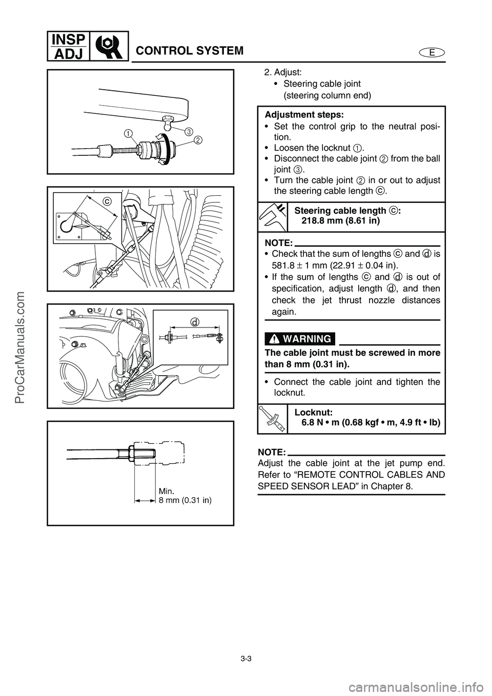
2. Adjust:
Steering cable joint
(steering column end)
NOTE:
Adjust the cable joint at the jet pump end.
Refer to “REMOTE CONTROL CABLES AND
SPEED SENSOR LEAD” in Chapter 8. Adjustment steps:
Set the control grip to the neutral posi-
tion.
Loosen the locknut 1
.
Disconnect the cable joint 2
from the ball
joint 3
.
Turn the cable joint 2
in or out to adjust
the steering cable length c
.
Steering cable length
c:
218.8 mm (8.61 in)
NOTE:
Check that the sum of lengths c
and d
is
581.8 ±
1 mm (22.91 ±
0.04 in).
If the sum of lengths c
and d
is out of
specification, adjust length d
, and then
check the jet thrust nozzle distances
again.
WARNING
The cable joint must be screwed in more
than 8 mm (0.31 in).
Connect the cable joint and tighten the
locknut.
T R..
Locknut:
6.8 N m (0.68 kgf m, 4.9 ft lb)
c
d
ProCarManuals.com
Page 53 of 347
3-4
E
INSP
ADJ
CONTROL SYSTEM
Throttle cable inspection and adjustment
NOTE:
Before adjusting the throttle lever free play,
check the trolling speed.
1. Measure:
Throttle lever free play a
Out of specification →
Adjust.
Throttle cable length b
Out of specification →
Adjust.
NOTE:
Check that the throttle cable length b
is 18.4
±
1 mm (0.72 ±
0.04 in). Adjust if necessary.
Adjust the throttle lever free play at the throt-
tle lever end of the throttle cable.
Throttle lever free play
a:
4–7 mm (0.16–0.28 in)
Throttle cable length
b:
18.4
± 1 mm (0.72
± 0.04 in)
b
2. Adjust:
Throttle lever free play a
Adjustment steps:
a. Remove the handlebar cover.
b. Loosen the locknut 1
.
c. Turn the adjuster 2
in or out until the
specified free play is obtained.
Turn in Free play is increased.
Turn out Free play is decreased.
d. Tighten the locknut 1
.
NOTE:
If the throttle cable free play cannot be
adjusted properly, replace the throttle cable.
ProCarManuals.com
Page 54 of 347
3-5
E
INSP
ADJ
CONTROL SYSTEM
WARNING
After adjusting the free play, turn the han-
dlebar to the right and left and make sure
that the trolling speed does not increase.e. Install the handlebar cover.
T R..
Lower handlebar cover screw:
3.7 N m (0.37 kgf m, 2.7 ft lb)
LOCTITE 242
Upper handlebar cover screw:
1.1 N m (0.11 kgf m, 0.8 ft lb)
Shift cable inspection and adjustment
(Deluxe model only)
1. Check:
Reverse gate stopper lever position
Incorrect →
Adjust.
2. Adjust:
Shift cable joint Checking steps:
Set the shift lever to the reverse position.
Check that the reverse gate 1
contacts
the stopper 2
.
Adjustment steps:
Loosen the locknut 1
.
Disconnect the cable joint 2
from the ball
joint 3
.
Situate the reverse gate to the stopper.
Turn the cable joint in or out to align it
with the ball joint.
Turn in Length is decreased.
Turn out Length is increased.
1
23
ProCarManuals.com
Page 55 of 347
3-6
E
INSP
ADJ
CONTROL SYSTEM
Turn out the cable joint nine times a
to
extend the cable 7 mm (0.28 in) from the
aligned position.
WARNING
The cable joint must be screwed in more
than 8 mm (0.31 in).
Connect the cable joint and tighten the
locknut.
T R..
Locknut:
3.8 N m (0.38 kgf m, 2.7 ft lb)
Trolling speed inspection
1. Inspect:
Trolling speed
Trolling speed:
1,550–1,750 r/min
Checking steps (watercraft in water):
Start the engine and allow it to warm up
for 15 minutes.
Check the engine trolling speed using the
tachometer of the multifunction meter or
using the Yamaha Diagnostic System.
ProCarManuals.com
Page 56 of 347
3-7
E
INSP
ADJ
FUEL SYSTEM
FUEL SYSTEM
WARNING
When removing fuel system parts, wrap
them in a cloth and take care that no fuel
spills into the engine compartment.
Fuel line inspection
1. Inspect:
Fuel pump filter
Clog/contaminants →
Clean.
Refer to “FUEL TANK AND FUEL
PUMP MODULE” in Chapter 4.
Fuel hose
Cracks/damage →
Replace.
O-rings (quick connector)
Cracks/damage →
Replace the quick
connector.
Fuel rail
Cracks/damage →
Replace.
Refer to “FUEL INJECTION SYSTEM”
in Chapter 4.
Fuel filler hose
Fuel filler cap
Cracks/damage →
Replace.
2. Inspect:
Fuel tank
Cracks/damage →
Replace.
Water accumulation →
Remove.
NOTE:
To remove water from the fuel tank, remove
the fuel filler hose 1
and use a siphon pump.
Refer to “FUEL TANK AND FUEL PUMP
MODULE” in Chapter 4.
1
ProCarManuals.com