Page 1 of 5135
010LE±01
D30402
D30403
A
BC D
E
FG H
01±4
± INTRODUCTIONIDENTIFICATION INFORMATION
AVENSIS REPAIR MANUAL (RM1018E)
IDENTIFICATION INFORMATION
VEHICLE IDENTIFICATION AND SERIAL NUMBERS
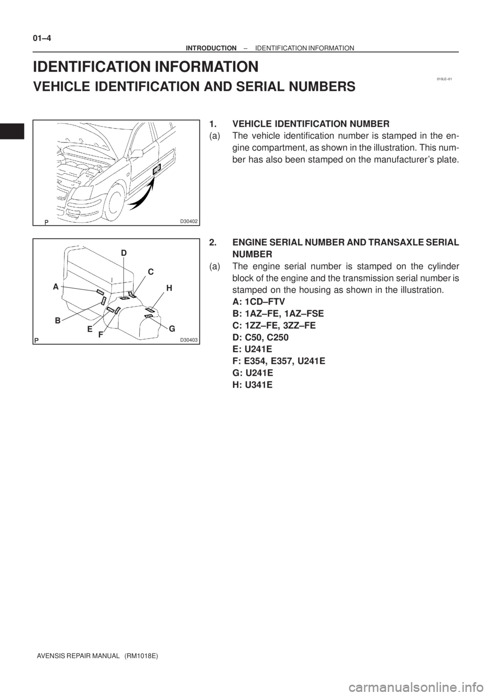
1. VEHICLE IDENTIFICATION NUMBER
(a) The vehicle identification number is stamped in the en-
gine compartment, as shown in the illustration. This num-
ber has also been stamped on the manufacturer's plate.
2. ENGINE SERIAL NUMBER AND TRANSAXLE SERIAL
NUMBER
(a) The engine serial number is stamped on the cylinder
block of the engine and the transmission serial number is
stamped on the housing as shown in the illustration.
A: 1CD±FTV
B: 1AZ±FE, 1AZ±FSE
C: 1ZZ±FE, 3ZZ±FE
D: C50, C250
E: U241E
F: E354, E357, U241E
G: U241E
H: U341E
Page 5 of 5135
022J5±01
± PREPARATIONENGINE CONTROL SYSTEM
02±3
AVENSIS REPAIR MANUAL (RM1018E)
ENGINE CONTROL SYSTEM
PREPARATION
SST
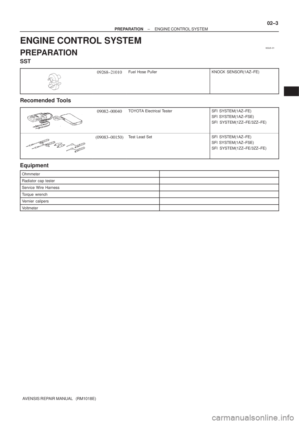
09268±21010Fuel Hose PullerKNOCK SENSOR(1AZ±FE)
Recomended Tools
09082±00040TOYOTA Electrical TesterSFI SYSTEM(1AZ±FE)
SFI SYSTEM(1AZ±FSE)
SFI SYSTEM(1ZZ±FE/3ZZ±FE)
(09083±00150)Test Lead SetSFI SYSTEM(1AZ±FE)
SFI SYSTEM(1AZ±FSE)
SFI SYSTEM(1ZZ±FE/3ZZ±FE)
Equipment
Ohmmeter
Radiator cap tester
Service Wire Harness
Torque wrench
Vernier calipers
Voltmeter
Page 6 of 5135
022LX±01
± PREPARATIONDIAGNOSTICS
02±1
AVENSIS REPAIR MANUAL (RM1018E)
DIAGNOSTICS
PREPARATION
SST
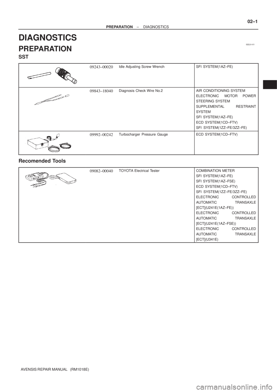
09243±00020Idle Adjusting Screw WrenchSFI SYSTEM(1AZ±FE)
09843±18040Diagnosis Check Wire No.2AIR CONDITIONING SYSTEM
ELECTRONIC MOTOR POWER
STEERING SYSTEM
SUPPLEMENTAL RESTRAINT
SYSTEM
SFI SYSTEM(1AZ±FE)
ECD SYSTEM(1CD±FTV)
SFI SYSTEM(1ZZ±FE/3ZZ±FE)
09992±00242Turbocharger Pressure GaugeECD SYSTEM(1CD±FTV)
Recomended Tools
09082±00040TOYOTA Electrical TesterCOMBINATION METER
SFI SYSTEM(1AZ±FE)
SFI SYSTEM(1AZ±FSE)
ECD SYSTEM(1CD±FTV)
SFI SYSTEM(1ZZ±FE/3ZZ±FE)
ELECTRONIC CONTROLLED
AUTOMATIC TRANSAXLE
[ECT](U241E(1AZ±FE))
ELECTRONIC CONTROLLED
AUTOMATIC TRANSAXLE
[ECT](U241E(1AZ±FSE))
ELECTRONIC CONTROLLED
AUTOMATIC TRANSAXLE
[ECT](U341E)
Page 7 of 5135
02±2
± PREPARATIONDIAGNOSTICS
AVENSIS REPAIR MANUAL (RM1018E)
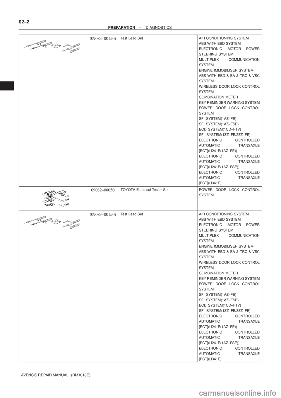
(09083±00150)Test Lead SetAIR CONDITIONING SYSTEM
ABS WITH EBD SYSTEM
ELECTRONIC MOTOR POWER
STEERING SYSTEM
MULTIPLEX COMMUNICATION
SYSTEM
ENGINE IMMOBILISER SYSTEM
ABS WITH EBD & BA & TRC & VSC
SYSTEM
WIRELESS DOOR LOCK CONTROL
SYSTEM
COMBINATION METER
KEY REMINDER WARNING SYSTEM
POWER DOOR LOCK CONTROL
SYSTEM
SFI SYSTEM(1AZ±FE)
SFI SYSTEM(1AZ±FSE)
ECD SYSTEM(1CD±FTV)
SFI SYSTEM(1ZZ±FE/3ZZ±FE)
ELECTRONIC CONTROLLED
AUTOMATIC TRANSAXLE
[ECT](U241E(1AZ±FE))
ELECTRONIC CONTROLLED
AUTOMATIC TRANSAXLE
[ECT](U241E(1AZ±FSE))
ELECTRONIC CONTROLLED
AUTOMATIC TRANSAXLE
[ECT](U341E)
09082±00050TOYOTA Electrical Tester SetPOWER DOOR LOCK CONTROL
SYSTEM
(09083±00150)Test Lead SetAIR CONDITIONING SYSTEM
ABS WITH EBD SYSTEM
ELECTRONIC MOTOR POWER
STEERING SYSTEM
MULTIPLEX COMMUNICATION
SYSTEM
ENGINE IMMOBILISER SYSTEM
ABS WITH EBD & BA & TRC & VSC
SYSTEM
WIRELESS DOOR LOCK CONTROL
SYSTEM
COMBINATION METER
KEY REMINDER WARNING SYSTEM
POWER DOOR LOCK CONTROL
SYSTEM
SFI SYSTEM(1AZ±FE)
SFI SYSTEM(1AZ±FSE)
ECD SYSTEM(1CD±FTV)
SFI SYSTEM(1ZZ±FE/3ZZ±FE)
ELECTRONIC CONTROLLED
AUTOMATIC TRANSAXLE
[ECT](U241E(1AZ±FE))
ELECTRONIC CONTROLLED
AUTOMATIC TRANSAXLE
[ECT](U241E(1AZ±FSE))
ELECTRONIC CONTROLLED
AUTOMATIC TRANSAXLE
[ECT](U341E)
Page 24 of 5135
± INTRODUCTIONHOW TO TROUBLESHOOT ECU CONTROLLED
SYSTEMS01±25
AVENSIS REPAIR MANUAL (RM1018E)
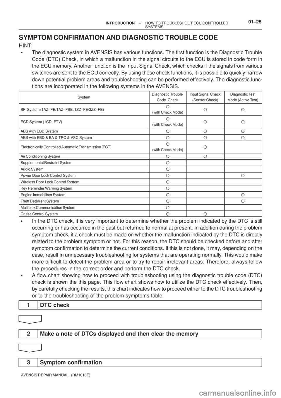
SYMPTOM CONFIRMATION AND DIAGNOSTIC TROUBLE CODE
HINT:
�The diagnostic system in AVENSIS has various functions. The first function is the Diagnostic Trouble
Code (DTC) Check, in which a malfunction in the signal circuits to the ECU is stored in code form in
the ECU memory. Another function is the Input Signal Check, which checks if the signals from various
switches are sent to the ECU correctly. By using these check functions, it is possible to quickly narrow
down potential problem areas and troubleshooting can be performed effectively. The diagnostic func-
tions are incorporated in the following systems in the AVENSIS.
SystemDiagnostic Trouble
Code CheckInput Signal Check
(Sensor Check)Diagnostic Test
Mode (Active Test)
SFI System (1AZ±FE/1AZ±FSE, 1ZZ±FE/3ZZ±FE)�
(with Check Mode)��
ECD System (1CD±FTV)�
(with Check Mode)��
ABS with EBD System���
ABS with EBD & BA & TRC & VSC System���
Electronically Controlled Automatic Transmission [ECT]�
(with Check Mode)�
Air Conditioning System��
Supplemental Restraint System�
Audio System�
Power Door Lock Control System��
Wireless Door Lock Control System�
Key Reminder Warning System�
Engine Immobiliser System��
Theft Deterrent System��
Multiplex Communication System�
Cruise Control System��
�In the DTC check, it is very important to determine whether the problem indicated by the DTC is still
occurring or has occurred in the past but returned to normal at present. In addition during the problem
symptom check, it a check must be made on whether the malfunction indicated by the DTC is directly
related to the problem symptom or not. For this reason, the DTC should be checked before and after
symptom confirmation to determine the current conditions. If this is not done, it may, depending on the
case, result in unnecessary troubleshooting for systems that are operating normally. This would make
more difficult to detect the problem area or to try to repair irrelevant areas. Therefore, always follow
the procedures in the correct order and perform the DTC check.
�A flow chart showing how to proceed with troubleshooting using the diagnostic trouble code (DTC)
check is shown the this page. This flow chart shows how to utilize the DTC check effectively. Then,
by carefully checking the results, this chart indicates how to proceed either to the DTC troubleshooting
or to the troubleshooting of the problem symptoms table.
1 DTC check
2 Make a note of DTCs displayed and then clear the memory
3 Symptom confirmation
Page 31 of 5135

010B6±13
±
INTRODUCTION HOW TO TROUBLESHOOT ECU CONTROLLED
SYSTEMS01±21
AVENSIS REPAIR MANUAL (RM1018E)
HOW TO TROUBLESHOOT ECU CONTROLLED SYSTEMS
GENERAL INFORMATION
There are many ECU controlled systems used in the AVENSIS. In general, ECU controlled system are con-
sidered to be very intricate and require a high level of technical knowledge an\
d expert skill to troubleshoot.
The fact is, however, that if you proceed by inspecting the circuits one by one, troubleshoo\
ting of these sys-
tems is not complex. If you have adequate understanding of the system and ba\
sic knowledge of electricity,
the problem can be accurately diagnosed and fixed. This manual is design\
ed based on the above principle
to help service technicians perform accurate and effective troubleshooting, and is compiled for the following
major ECU controlled systems:
The troubleshooting procedures are described on the following pages.
SystemPage
1. SFI System [1ZZ±FE, 3ZZ±FE]05±1
2. SFI System [1AZ±FE]05±143
3. SFI System [1AZ±FSE]05±290
4. ECD System [1CD±FTV]05±523
5. ABS with EBD System05±696
6. ABS with EBD & BA & TRC & VSC System05±752
7. Electronic Controlled Automatic Transmission [ECT] [U241 (1AZ±FE)]05±856
8. Electronic Controlled Automatic Transmission [ECT] [U241 (1AZ±FSE)]05±915
9. Electronic Controlled Automatic Transmission [ECT] [U341]05±980
10.Electronic Motor Power Steering System05±1042
11. Air Conditioning System05±1088
12.Combustion Type Power Heater System05±1161
13.Supplemental Restraint System05±1181
14.Audio System05±1393
15.Navigation System05±1435
16.Combination Meter05±1497
17.Power Door Lock Control System05±1534
18.Wireless Door Lock Control System05±1568
19.Key Reminder Warning System05±1586
20.Engine Immobiliser System05±1599
21.Theft Deterrent System05±1627
22.Multiplex Communication System05±1654
23.Cruise Control System05±1697
FOR USING HAND±HELD TESTER
�Before using the tester, the tester's operator manual should be read thoroughly.
�If the tester cannot communicate with the ECU controlled systems when you \
have connected the cable
of tester to the DLC3, turned the ignition switch ON and operated the test\
er, there is a problem on the
vehicle side or tester side.
(1) If the communication is normal when the tester is connected to another veh\
icle, inspect the diag-
nosis data link line (Bus �line) or ECU power circuit of the vehicle.
(2) If the communication is still impossible when the tester is connected to a\
nother vehicle, the prob- lem is probably in the tester itself, so perform the Self Test procedures outlined in the Tester Oper-
ator 's Manual.
Page 54 of 5135
02±32
± PREPARATIONDRIVE SHAFT / PROPELLER SHAFT
AVENSIS REPAIR MANUAL (RM1018E)
09040±00011Hexagon Wrench SetFRONT AXLE HUB SUB±ASSY LH
FRONT DRIVE SHAFT
(09043±20060)Socket Hexagon Wrench 6FRONT AXLE HUB SUB±ASSY LH
FRONT DRIVE SHAFT
09904±00010Expander SetFRONT DRIVE SHAFT
(09904±00050)No. 4 ClawFRONT DRIVE SHAFT
09905±00012Snap Ring No.1 ExpanderFRONT DRIVE SHAFT
09905±00013Snap Ring PliersFRONT AXLE HUB SUB±ASSY LH
Equipment
Torque wrench
Dial indicator with magnetic base
Lubricant
ItemCapacity
Front drive shaft
1AZ±FSE, 1AZ±FE, 1CD±FTV Outboard joint grease:
Inboard joint grease:
3ZZ±FE, 1ZZ±FE Outboard joint grease:
Inboard joint grease:
152.0 ± 162.0 g (5.4 ± 5.7 oz.)
170.0 ± 190.0 g (6.0 ± 6.7 oz.)
85.0 ± 105.0 g (3.0 ± 3.7 oz.)
125.5 ± 135.5 g (4.4 ± 4.8 oz.)
Page 59 of 5135
022J9±01
02±24
± PREPARATIONSTARTING & CHARGING
AVENSIS REPAIR MANUAL (RM1018E)
STARTING & CHARGING
PREPARATION
SST
09249±63010Torque Wrench AdaptorGENERATOR
ASSY(1AZ±FE/1AZ±FSE)
Recomended Tools
09082±00040TOYOTA Electrical TesterSTARTING SYSTEM(1AZ±FE)
STARTING SYSTEM(1AZ±FSE)
STARTING SYSTEM
(1ZZ±FE/3ZZ±FE)
(09083±00150)Test Lead SetSTARTING SYSTEM(1AZ±FE)
STARTING SYSTEM(1AZ±FSE)
STARTING SYSTEM
(1ZZ±FE/3ZZ±FE)
09216±00021Belt Tension GaugeGENERATOR ASSY(1CD±FTV)
Equipment
Slide calipers
Ammeter(A)
Ohmmeter
Radiator cap tester
Torque wrench
Service Wire Harness