Page 669 of 5135
A56992
E2
PIM
VC
T5
Wire Harness Side
Manifold Absolute
Pressure Sensor Connector
A81088
PIM
VC
E2E12ECM Connector
E13
±
DIAGNOSTICS ECD SYSTEM(1CD±FTV)
05±587
AVENSIS REPAIR MANUAL (RM1018E)
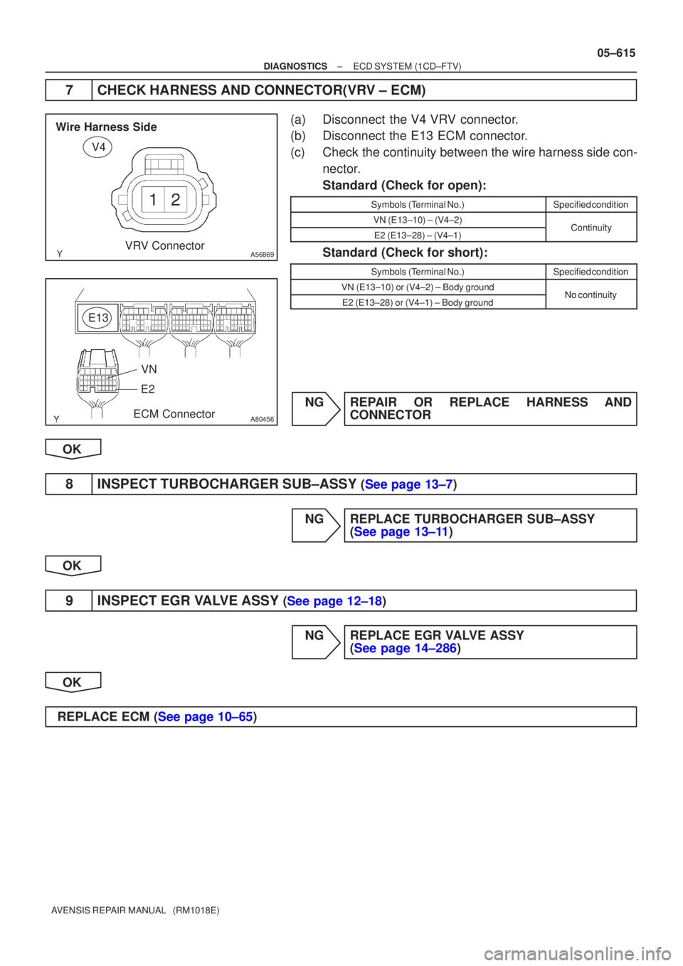
4CHECK HARNESS AND CONNECTOR(MANIFOLD ABSOLUTE PRESSURE
SENSOR ± ECM)
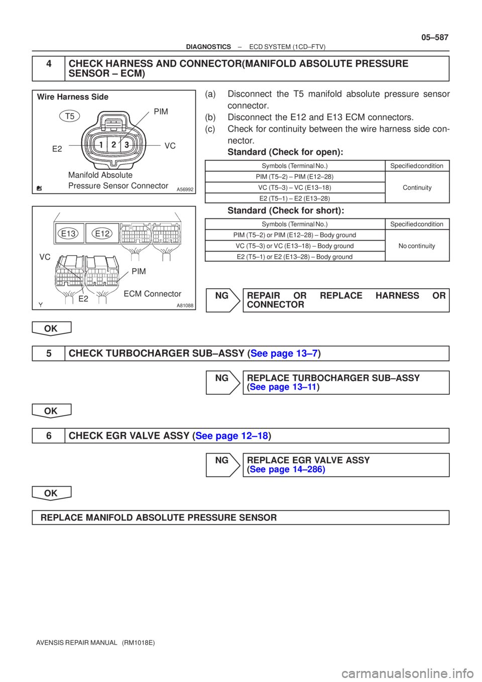
(a)Disconnect the T5 manifold absolute pressure sensor
connector.
(b)Disconnect the E12 and E13 ECM connectors.
(c)Check for continuity between the wire harness side con- nector.
Standard (Check for open):
Symbols (Terminal No.)Specified condition
PIM (T5±2) ± PIM (E12±28)
VC (T5±3) ± VC (E13±18)Continuity
E2 (T5±1) ± E2 (E13±28)
y
Standard (Check for short):
Symbols (Terminal No.)Specified condition
PIM (T5±2) or PIM (E12±28) ± Body ground
VC (T5±3) or VC (E13±18) ± Body groundNo continuity
E2 (T5±1) or E2 (E13±28) ± Body ground
y
NGREPAIR OR REPLACE HARNESS OR CONNECTOR
OK
5CHECK TURBOCHARGER SUB±ASSY (See page 13±7)
NG REPLACE TURBOCHARGER SUB±ASSY (See page 13±11)
OK
6CHECK EGR VALVE ASSY (See page 12±18)
NG REPLACE EGR VALVE ASSY (See page 14±286)
OK
REPLACE MANIFOLD ABSOLUTE PRESSURE SENSOR
Page 707 of 5135
A82939
+B2
+B1EGR2
EGR1 EGR4
EGR3
05±630
±
DIAGNOSTICS ECD SYSTEM(1CD±FTV)
AVENSIS REPAIR MANUAL (RM1018E)
1CHECK OTHER DTC OUTPUT(BESIDES P0400 AND/OR P0403)
(a)Read the DTC using the hand±held tester.
Result:
Display (DTC output)Proceed
P0400 and/or P0403 are outputA
P0400 and/or P0403 and other DTCs are outputB
HINT:
If any other codes besides P0400 and/or P0403 are output, perform the trou\
bleshooting for those DTCs first. BGO TO RELEVANT DTC CHART(See page 05±544)
A
2READ VALUE OF HAND±HELD TESTER(MASS AIR FLOW RATE)
(a)Connect the hand±held tester to the DLC3.
(b)Turn the ignition switch ON and push the hand±held tester main switch \
ON.
(c)Start the engine.
(d)Warm up the engine, the engine coolant temperature should be above 75 �C (167 �F) and bellow 90 �C
(194 �F).
(e)Select the item ºDIAGNOSIS / OBD/MOBD / DATA LIST / ALL / MAFº.
(f)Check that the MAF reading during idling. Result: MAF greater than 4 g/s but less than 16 g/s
(g)Force the EGR valve to operate with a hand±held tester, make the valve opening 0, and check that
the AFM reading during idling.
Result: MAF greater than 10 g/s but less than 16 g/s
NGREPLACE EGR VALVE ASSY (See page 14±286)
OK
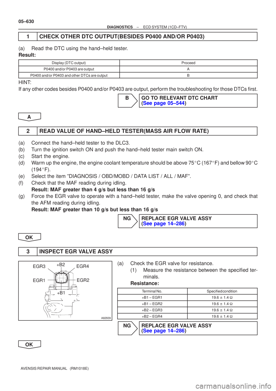
3INSPECT EGR VALVE ASSY
(a)Check the EGR valve for resistance. (1)Measure the resistance between the specified ter-minals.
Resistance:
Terminal No.Specified condition
+B1 ± EGR119.6 � 1.4 �
+B1 ± EGR219.6 � 1.4 �
+B2 ± EGR319.6 � 1.4 �
+B2 ± EGR419.6 � 1.4 �
NGREPLACE EGR VALVE ASSY
(See page 14±286)
OK
Page 726 of 5135
A56869
V4
VRV Connector
Wire Harness Side
A80456
E13
ECM Connector
E2
VN
±
DIAGNOSTICS ECD SYSTEM(1CD±FTV)
05±615
AVENSIS REPAIR MANUAL (RM1018E)
7CHECK HARNESS AND CONNECTOR(VRV ± ECM)
(a)Disconnect the V4 VRV connector.
(b)Disconnect the E13 ECM connector.
(c)Check the continuity between the wire harness side con-
nector.
Standard (Check for open):
Symbols (Terminal No.)Specified condition
VN (E13±10) ± (V4±2)ContinuityE2 (E13±28) ± (V4±1)Continuity
Standard (Check for short):
Symbols (Terminal No.)Specified condition
VN (E13±10) or (V4±2) ± Body groundNocontinuityE2 (E13±28) or (V4±1) ± Body groundNo continuity
NGREPAIR OR REPLACE HARNESS AND CONNECTOR
OK
8INSPECT TURBOCHARGER SUB±ASSY (See page 13±7)
NG REPLACE TURBOCHARGER SUB±ASSY (See page 13±11)
OK
9INSPECT EGR VALVE ASSY (See page 12±18)
NG REPLACE EGR VALVE ASSY (See page 14±286)
OK
REPLACE ECM (See page 10±65)
Page 763 of 5135
A82883
Pressure Discharge Valve
A81461
E4
Wire Harness SideEDU Connector COM3
A81462
E5
Wire Harness Side
EDU Connector PRV
A81694
P3
Wire Harness Side
Pressure Discharge valve
Connector
#G COMG
±
DIAGNOSTICS ECD SYSTEM(1CD±FTV)
05±669
AVENSIS REPAIR MANUAL (RM1018E)
2INSPECT COMMON RAIL ASSY (PRESSURE DISCHARGE VALVE)
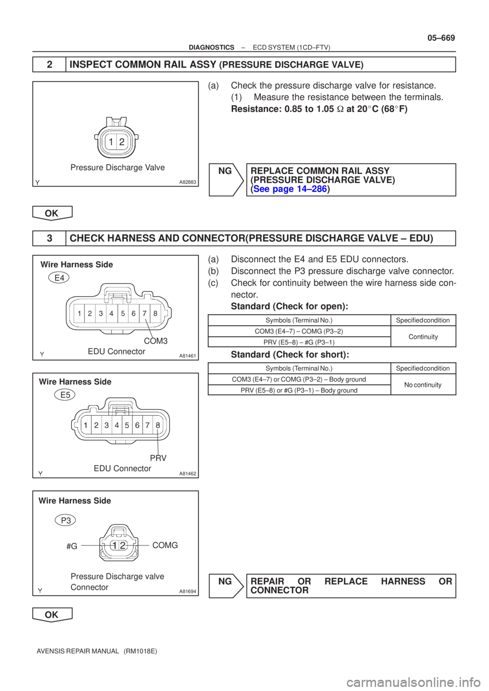
(a)Check the pressure discharge valve for resistance. (1)Measure the resistance between the terminals.
Resistance: 0.85 to 1.05 � at 20 �C (68 �F)
NGREPLACE COMMON RAIL ASSY (PRESSURE DISCHARGE VALVE)
(See page 14±286)
OK
3 CHECK HARNESS AND CONNECTOR(PRESSURE DISCHARGE VALVE ± EDU)
(a) Disconnect the E4 and E5 EDU connectors.
(b) Disconnect the P3 pressure discharge valve connector.
(c) Check for continuity between the wire harness side con- nector.
Standard (Check for open):
Symbols (Terminal No.)Specified condition
COM3 (E4±7) ± COMG (P3±2)ContinuityPRV (E5±8) ± #G (P3±1)Continuity
Standard (Check for short):
Symbols (Terminal No.)Specified condition
COM3 (E4±7) or COMG (P3±2) ± Body groundNo continuityPRV (E5±8) or #G (P3±1) ± Body groundNo continuity
NG REPAIR OR REPLACE HARNESS OR CONNECTOR
OK
Page 2044 of 5135
A78516
A78459
14±28
±
ENGINE MECHANICAL PARTIAL ENGINE ASSY(1ZZ±FE/3ZZ±FE)
AVENSIS REPAIR MANUAL (RM1018E)
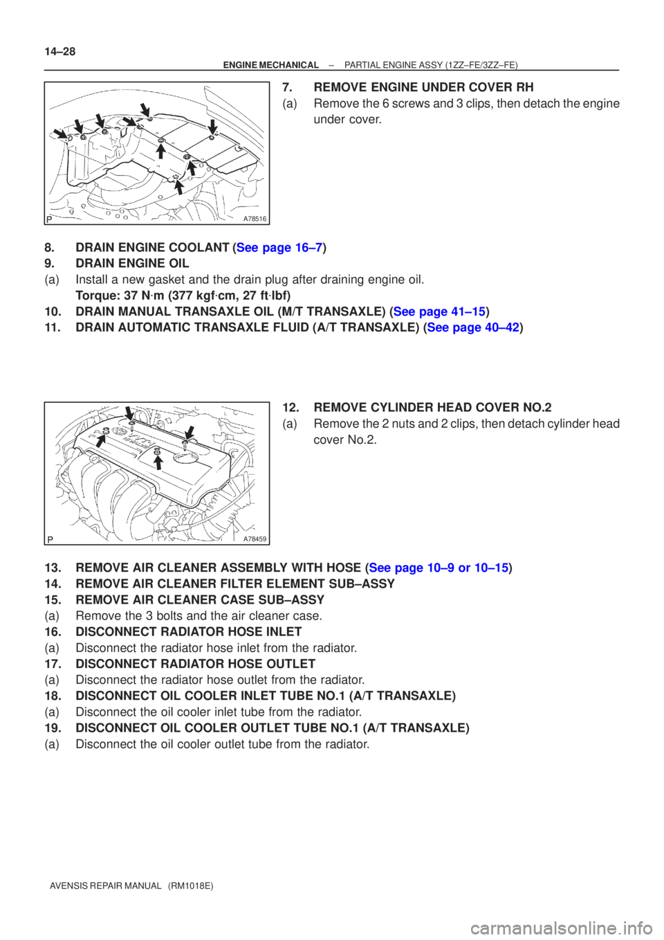
7.REMOVE ENGINE UNDER COVER RH
(a)Remove the 6 screws and 3 clips, then detach the engine under cover.
8.DRAIN ENGINE COOLANT(See page 16±7)
9. DRAIN ENGINE OIL
(a) Install a new gasket and the drain plug after draining engine oil. Torque: 37 N �m (377 kgf �cm, 27 ft �lbf)
10.DRAIN MANUAL TRANSAXLE OIL (M/T TRANSAXLE) (See page 41±15)
11.DRAIN AUTOMATIC TRANSAXLE FLUID (A/T TRANSAXLE) (See page 40±42)
12. REMOVE CYLINDER HEAD COVER NO.2
(a) Remove the 2 nuts and 2 clips, then detach cylinder headcover No.2.
13.REMOVE AIR CLEANER ASSEMBLY WITH HOSE (See page 10±9 or 10±15)
14. REMOVE AIR CLEANER FILTER ELEMENT SUB±ASSY
15. REMOVE AIR CLEANER CASE SUB±ASSY
(a) Remove the 3 bolts and the air cleaner case.
16. DISCONNECT RADIATOR HOSE INLET
(a) Disconnect the radiator hose inlet from the radiator.
17. DISCONNECT RADIATOR HOSE OUTLET
(a) Disconnect the radiator hose outlet from the radiator.
18. DISCONNECT OIL COOLER INLET TUBE NO.1 (A/T TRANSAXLE)
(a) Disconnect the oil cooler inlet tube from the radiator.
19. DISCONNECT OIL COOLER OUTLET TUBE NO.1 (A/T TRANSAXLE)
(a) Disconnect the oil cooler outlet tube from the radiator.
Page 2236 of 5135
A79420N´m (kgf´cm, ft´lbf)
: Specified torque
52 (530, 38)
52 (530, 38)
52 (530, 38)
52 (530, 38)
87 (887, 64)
80 (816, 59)
133 (1,356, 98)52 (530, 38)
72 (734, 53)
39 (398, 29)
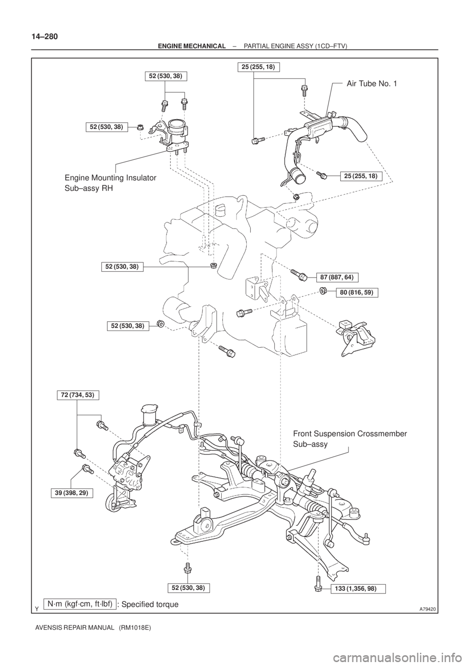
Engine Mounting Insulator
Sub±assy RHAir Tube No. 1
Front Suspension Crossmember
Sub±assy25 (255, 18)
25 (255, 18)
14±280
± ENGINE MECHANICALPARTIAL ENGINE ASSY (1CD±FTV)
AVENSIS REPAIR MANUAL (RM1018E)
Page 2237 of 5135
A79421N´m (kgf´cm, ft´lbf)
: Specified torque
88 (897, 65)
19 (195, 14)
64 (653, 47)
37 (377, 27)
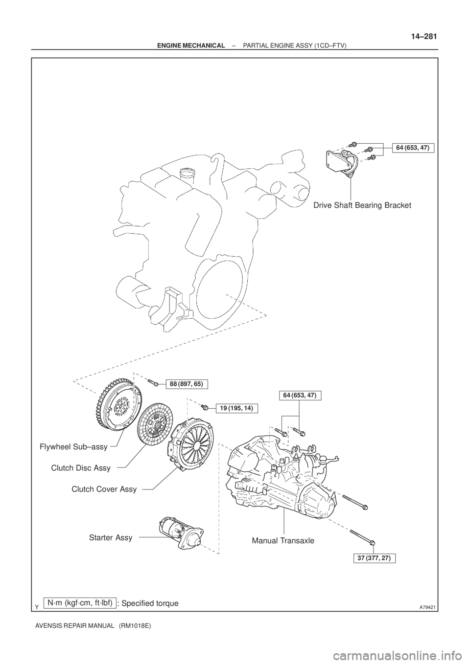
Drive Shaft Bearing Bracket
Flywheel Sub±assy
Clutch Cover Assy
Starter Assy
Manual Transaxle
Clutch Disc Assy
64 (653, 47)
± ENGINE MECHANICALPARTIAL ENGINE ASSY (1CD±FTV)
14±281
AVENSIS REPAIR MANUAL (RM1018E)
Page 2238 of 5135
A79422
N´m (kgf´cm, ft´lbf)
: Specified torque
� Non±reusable part� Gasket
� Gasket � Gasket
20 (204, 15)
20 (204, 15)
53 (540, 39)
13 (135, 9.7)
36 (367, 27)61 (622, 45)
56 (571, 41)
25 (255, 18)
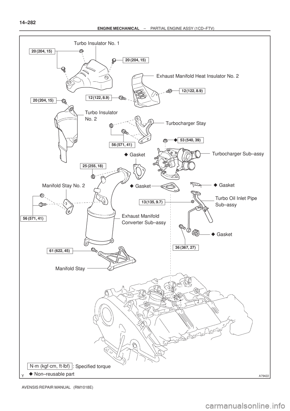
Turbo Insulator No. 1
Exhaust Manifold Heat Insulator No. 2
Turbocharger Stay
Turbocharger Sub±assy
Turbo Oil Inlet Pipe
Sub±assy
Manifold Stay Manifold Stay No. 2
Exhaust Manifold
Converter Sub±assy Turbo Insulator
No. 2
�
20 (204, 15)
12 (122, 8.9)
56 (571, 41)
� Gasket
12 (122, 8.9)
14±282
± ENGINE MECHANICALPARTIAL ENGINE ASSY (1CD±FTV)
AVENSIS REPAIR MANUAL (RM1018E)