Page 2308 of 5135
±
ENGINE MECHANICAL CAMSHAFT (1CD±FTV)
14±325
AVENSIS REPAIR MANUAL (RM1018E)
59.INSTALL TIMING CHAIN COVER PLATE(See page 14±307)
60.INSTALL TRANSVERSE ENGINE ENGINE MOUNTING BRACKET(See page 14±307)
61.INSTALL TIMING BELT GUIDE(See page 14±307)
62.INSTALL TIMING BELT NO.1 COVER(See page 14±307)
63.INSTALL TIMING BELT NO.2 COVER(See page 14±307)
64.INSTALL IDLER PULLEY SUB±ASSY(See page 14±307)
65.INSTALL CRANKSHAFT PULLEY(See page 14±307)
SST 09213±54015 (90105±08076), 09330±00021
66.INSTALL ENGINE MOUNTING INSULATOR SUB±ASSY RH(See page 14±307)
67.INSTALL POWER STEERING IDLE PULLEY BRACKET (See page 14±286)
68. ADJUST V (COOLER COMPRESSOR TO CRANKSHAFT PULLEY) BELT NO.1 (See page 14±269)
69.INSTALL INJECTOR DRIVER (See page 14±286)
70.INSTALL AIR TUBE NO.1 (See page 14±270)
71. INSTALL VACUUM RESERVOIR SUB±ASSY Torque: 8.3 N �m (85 kgf �cm, 73 in. �lbf)
72.INSTALL AIR CLEANER ASSY (See page 14±286)
73. INSTALL ENGINE COVER NO.1 Torque: 8.0 N �m (82 kgf �cm, 71 in. �lbf)
74. INSTALL FRONT WHEEL RH
Torque: 103 N �m (1,050 kgf �cm, 76 ft �lbf)
75.CHECK FOR FUEL LEAKS(See page 11±60)
Page 2313 of 5135
141C6±01
A61184
A79179
A61182
SST (B)
SSTSST (A)
±
ENGINE MECHANICAL TIMING BELT(1CD±FTV)
14±307
AVENSIS REPAIR MANUAL (RM1018E)
REPLACEMENT
1.REMOVE FRONT WHEEL RH
2.REMOVE ENGINE UNDER COVER SUB±ASSY NO.1
3.REMOVE ENGINE UNDER COVER RH
4.REMOVE RADIATOR SUPPORT OPENING COVER
5.REMOVE ENGINE ROOM COVER SIDE
6.REMOVE ENGINE COVER NO.1
(a)Remove the 5 nuts and the engine cover.
7.REMOVE INJECTOR DRIVER (See page 14±286)
8.REMOVE V (COOLER COMPRESSOR TO CRANKSHAFT PULLEY) BELT NO.1
(See page 14±269)
9.REMOVE GENERATOR V BELT (See page 14±269)
10.SEPARATE POWER STEERING IDLE PULLEY BRACKET (See page 14±286)
11. REMOVE ENGINE MOUNTING INSULATORSUB±ASSY RH
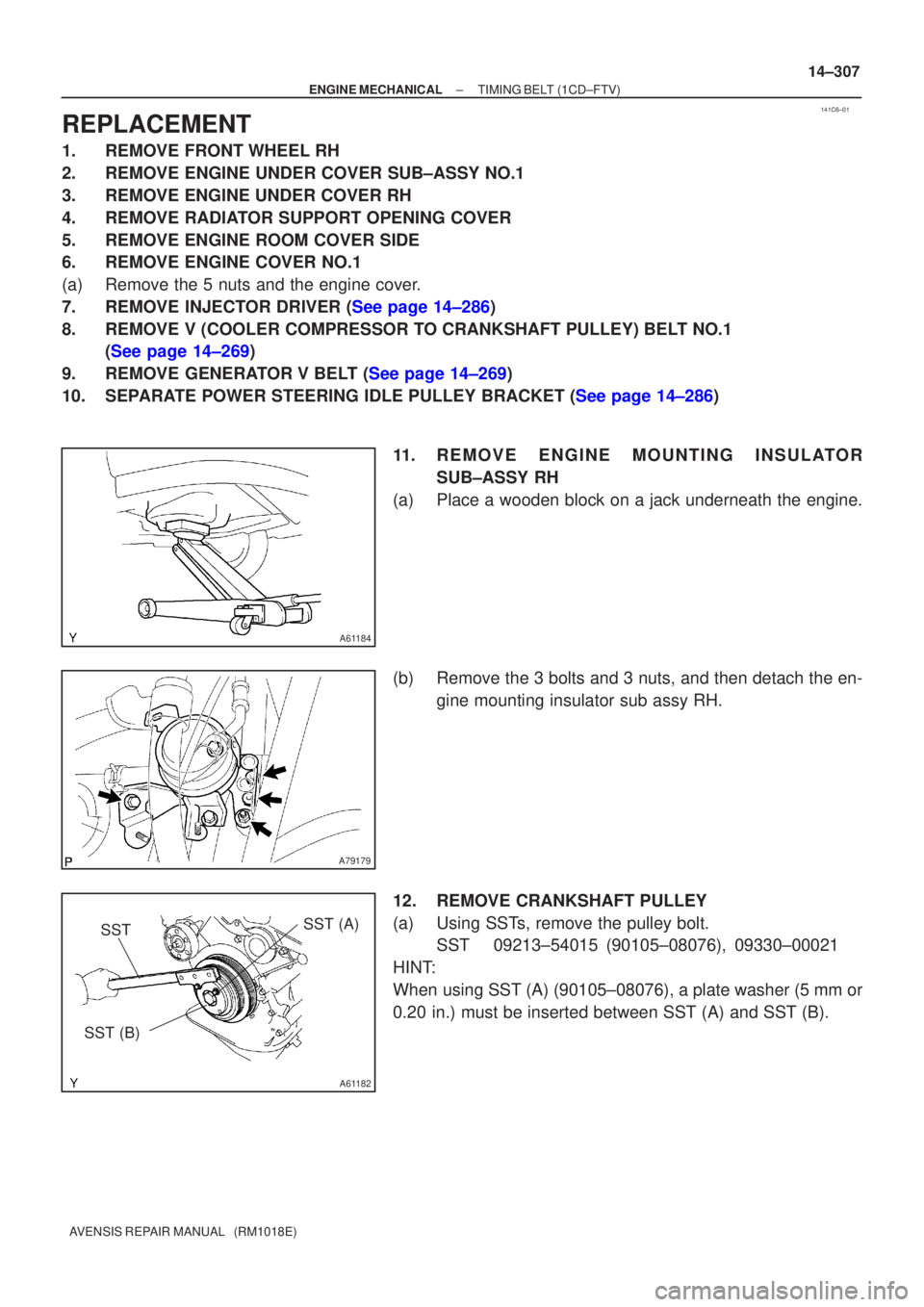
(a) Place a wooden block on a jack underneath the engine.
(b) Remove the 3 bolts and 3 nuts, and then detach the en- gine mounting insulator sub assy RH.
12. REMOVE CRANKSHAFT PULLEY
(a) Using SSTs, remove the pulley bolt. SST 09213±54015 (90105±08076), 09330±00021
HINT:
When using SST (A) (90105±08076), a plate washer (5 mm or
0.20 in.) must be inserted between SST (A) and SST (B).
Page 2318 of 5135
A09602
Seal
Packing
Gasket
Groove
A61186
SST
14±312
±
ENGINE MECHANICAL TIMING BELT(1CD±FTV)
AVENSIS REPAIR MANUAL (RM1018E)
(b)Install the No. 1 timing belt cover and the gasket with the 5 bolts and 5 seal washers.
Torque: 7.4 N �m (75 kgf �cm,65 in. �lbf)
(c)After installing the belt cover, check that there is no peel- ings of the gasket.
28.INSTALL TIMING BELT NO.2 COVER
(a)Check the timing belt cover gasket for cracks or deteriora- tions etc.
If the gasket has cracks or has deteriorated, replace it by the
following steps: (1)Using a screwdriver and gasket scraper, remove allthe old gasket.
(2)Thoroughly clean all components to remove all the loose material.
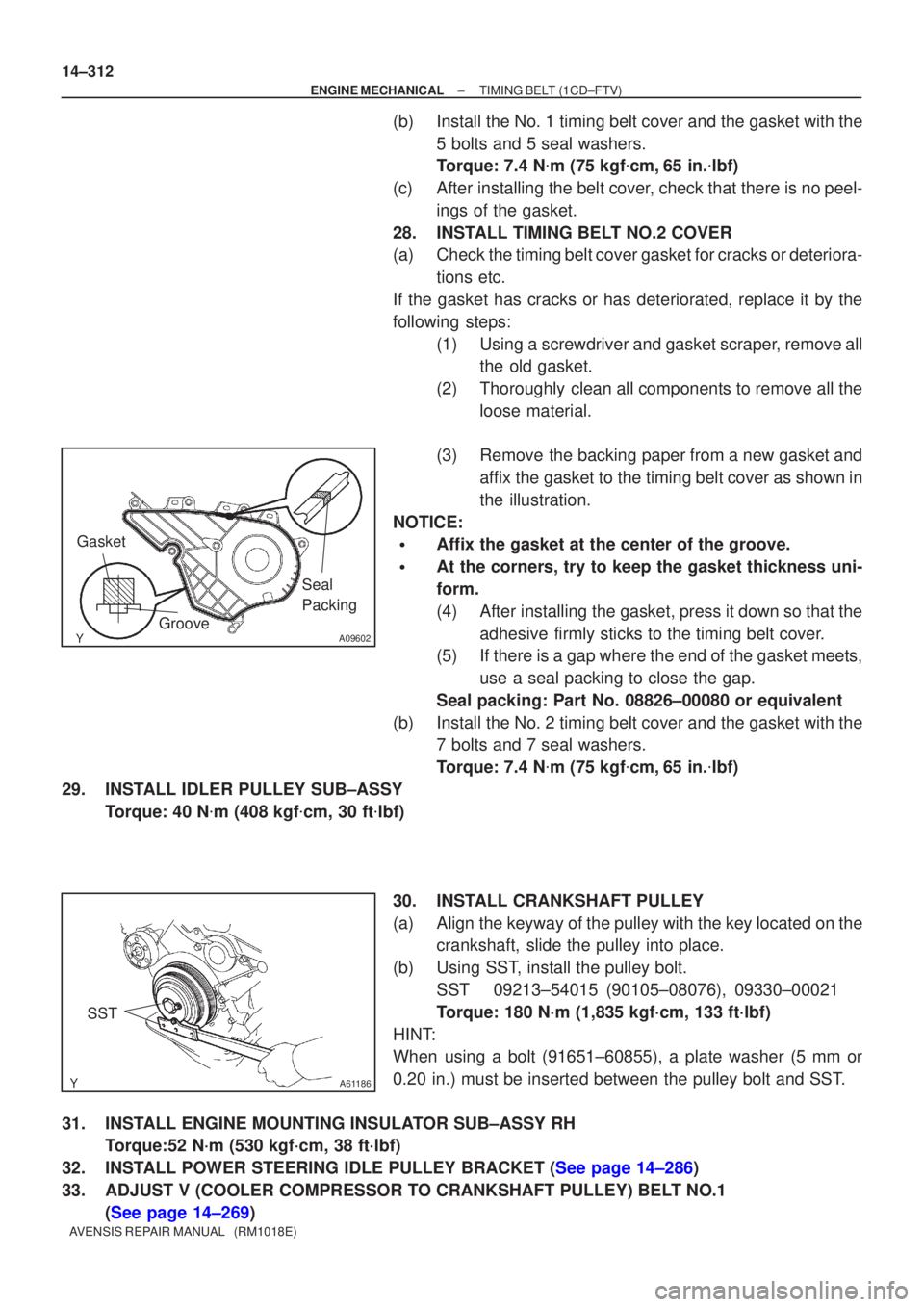
(3)Remove the backing paper from a new gasket and affix the gasket to the timing belt cover as shown in
the illustration.
NOTICE:
�Affix the gasket at the center of the groove.
�At the corners, try to keep the gasket thickness uni-
form.
(4)After installing the gasket, press it down so that the adhesive firmly sticks to the timing belt cover.
(5)If there is a gap where the end of the gasket meets,
use a seal packing to close the gap.
Seal packing: Part No. 08826±00080 or equivalent
(b)Install the No. 2 timing belt cover and the gasket with the 7 bolts and 7 seal washers.
Torque: 7.4 N �m (75 kgf �cm,65 in. �lbf)
29.INSTALL IDLER PULLEY SUB±ASSY Torque: 40 N �m (408 kgf �cm, 30 ft �lbf)
30.INSTALL CRANKSHAFT PULLEY
(a)Align the keyway of the pulley with the key located on the crankshaft, slide the pulley into place.
(b)Using SST, install the pulley bolt. SST09213±54015 (90105±08076), 09330±00021
Torque: 180 N´m (1,835 kgf´cm, 133 ft´lbf)
HINT:
When using a bolt (91651±60855), a plate washer (5 mm or
0.20 in.) must be inserted between the pulley bolt and SST.
31.INSTALL ENGINE MOUNTING INSULATOR SUB±ASSY RH Torque:52 N´m (530 kgf´cm, 38 ft´lbf)
32.INSTALL POWER STEERING IDLE PULLEY BRACKET (See page 14±286)
33. ADJUST V (COOLER COMPRESSOR TO CRANKSHAFT PULLEY) BELT NO.1 (See page 14±269)
Page 2319 of 5135
±
ENGINE MECHANICAL TIMING BELT(1CD±FTV)
14±313
AVENSIS REPAIR MANUAL (RM1018E)
34.INSTALL INJECTOR DRIVER (See page 14±286)
35. INSTALL ENGINE COVER NO.1
Torque: 8.0 N �m (82 kgf �cm, 71 in. �lbf)
36. INSTALL FRONT WHEEL RH Torque: 103 N �m (1,050 kgf �cm, 76 ft �lbf)
Page 2322 of 5135
141C4±01
A80094
14±286
±
ENGINE MECHANICAL PARTIAL ENGINE ASSY(1CD±FTV)
AVENSIS REPAIR MANUAL (RM1018E)
REPLACEMENT
1.REMOVE FRONT WHEELS
2.REMOVE ENGINE UNDER COVER LH
3.REMOVE ENGINE UNDER COVER SUB±ASSY NO.1
4.REMOVE ENGINE UNDER COVER RH
5.REMOVE RADIATOR SUPPORT OPENING COVER
6.REMOVE ENGINE ROOM COVER SIDE
7.DRAIN ENGINE COOLANT (See page 16±44)
8.DRAIN ENGINE OIL (See page 14±342)
9.DRAIN MANUAL TRANSAXLE OIL Torque: 49 N �m (500 kgf �cm,36 ft �lbf)
10.REMOVE ENGINE COVER NO.1
(a)Remove the 5 nuts and the engine cover.
11.REMOVE BATTERY
12.REMOVE AIR CLEANER ASSY
(a)Disconnect the connector.
(b)Remove the air cleaner cap together with the air cleaner hose.
(c)Remove the air cleaner filter element.
(d)Remove the 3 bolts and the air cleaner case.
13.DISCONNECT UNION TO CONNECTOR TUBE HOSE
14.REMOVE FUEL FILTER ASSY
(a)Disconnect the 2 fuel hose from the fuel filter (STD).
(b)Disconnect the 3 fuel hose from the fuel filter (COLD).
(c)Disconnect the connector (STD).
(d)Disconnect the 2 connectors (COLD).
(e)Remove the 2 bolts and the fuel filter.
15.REMOVE RADIATOR HOSE INLET
16.REMOVE RADIATOR HOSE OUTLET
17.DISCONNECT WATER BY±PASS HOSE NO.2
18.REMOVE ENGINE ROOM RELAY BLOCK NO.3
(a)Remove the 2 bolts and the engine room relay block.
19.REMOVE RADIATOR ASSY (W/ AIR CONDITIONING) (See page 16±51)
20. DISCONNECT HEATER INLET WATER HOSE
21. DISCONNECT HEATER OUTLET WATER HOSE
22. DISCONNECT FUEL HOSE NO.2
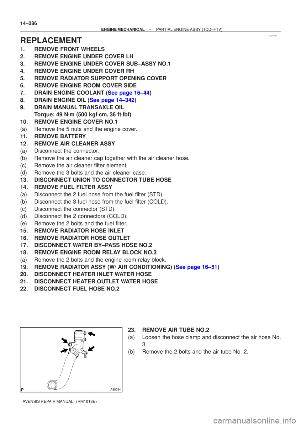
23. REMOVE AIR TUBE NO.2
(a) Loosen the hose clamp and disconnect the air hose No.3.
(b) Remove the 2 bolts and the air tube No. 2.
Page 2323 of 5135
A79178
A78277
±
ENGINE MECHANICAL PARTIAL ENGINE ASSY(1CD±FTV)
14±287
AVENSIS REPAIR MANUAL (RM1018E)
24.SEPARATE TRANSMISSION CONTROL CABLE ASSY
(a)Remove the 2 clips and 2 washers, separate the control cable assy.
25.REMOVE INJECTOR DRIVER
(a)Remove the 2 nuts which is used to secure the injector driver.
(b)Disconnect the injector driver connector and the harness clamp.
(c)Remove the injector driver.
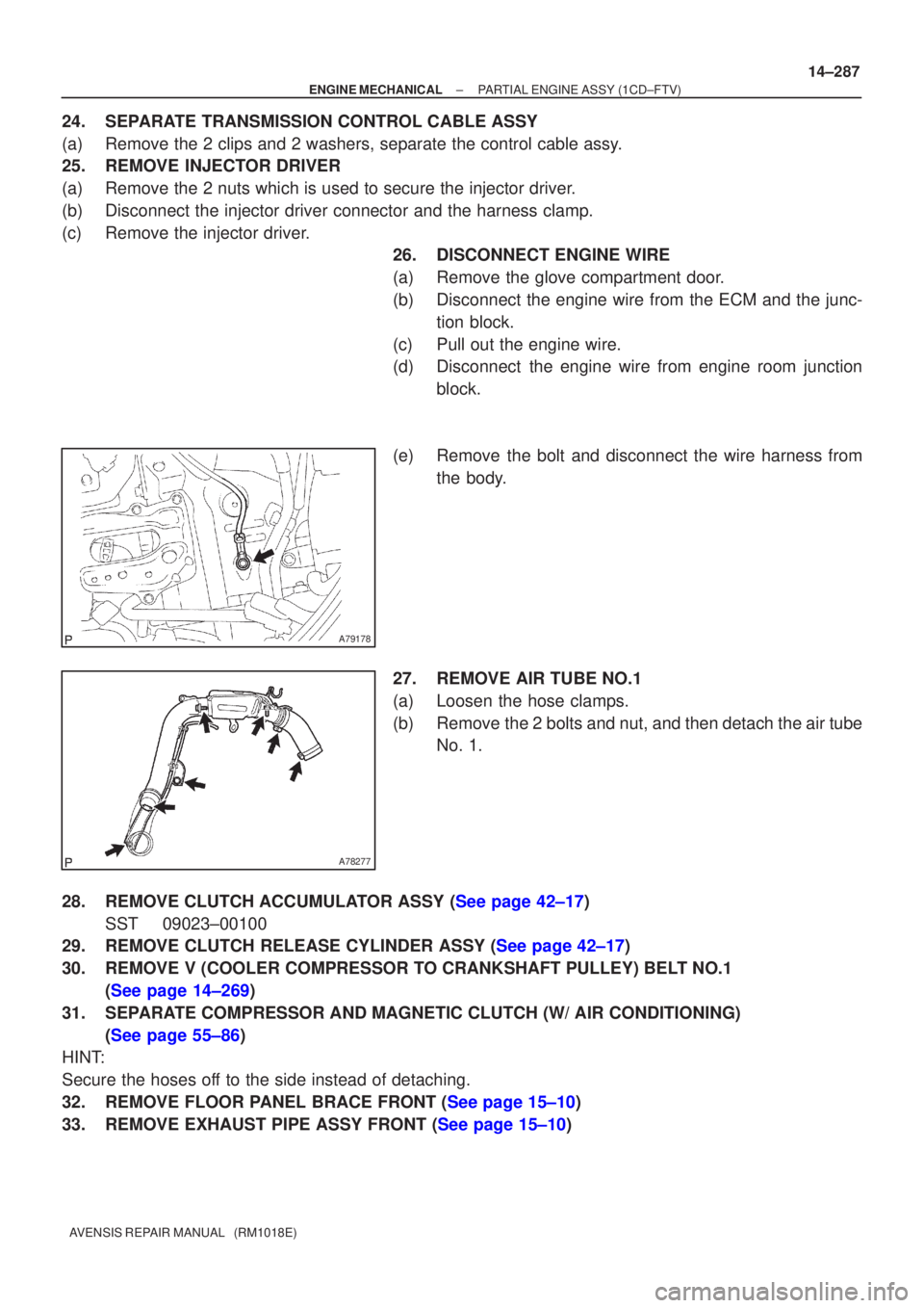
26.DISCONNECT ENGINE WIRE
(a)Remove the glove compartment door.
(b)Disconnect the engine wire from the ECM and the junc-
tion block.
(c)Pull out the engine wire.
(d)Disconnect the engine wire from engine room junction block.
(e)Remove the bolt and disconnect the wire harness from the body.
27.REMOVE AIR TUBE NO.1
(a)Loosen the hose clamps.
(b)Remove the 2 bolts and nut, and then detach the air tube No. 1.
28.REMOVE CLUTCH ACCUMULATOR ASSY (See page 42±17) SST 09023±00100
29.REMOVE CLUTCH RELEASE CYLINDER ASSY (See page 42±17)
30. REMOVE V (COOLER COMPRESSOR TO CRANKSHAFT PULLEY) BELT NO.1
(See page 14±269)
31. SEPARATE COMPRESSOR AND MAGNETIC CLUTCH (W/ AIR CONDITIONING) (See page 55±86)
HINT:
Secure the hoses off to the side instead of detaching.
32.REMOVE FLOOR PANEL BRACE FRONT (See page 15±10)
33.REMOVE EXHAUST PIPE ASSY FRONT (See page 15±10)
Page 2324 of 5135
A79140
A79184
14±288
±
ENGINE MECHANICAL PARTIAL ENGINE ASSY(1CD±FTV)
AVENSIS REPAIR MANUAL (RM1018E)
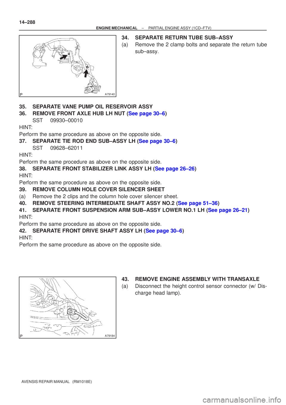
34.SEPARATE RETURN TUBE SUB±ASSY
(a)Remove the 2 clamp bolts and separate the return tube sub±assy.
35.SEPARATE VANE PUMP OIL RESERVOIR ASSY
36.REMOVE FRONT AXLE HUB LH NUT (See page 30±6) SST09930±00010
HINT:
Perform the same procedure as above on the opposite side.
37.SEPARATE TIE ROD END SUB±ASSY LH (See page 30±6) SST 09628±62011
HINT:
Perform the same procedure as above on the opposite side.
38.SEPARATE FRONT STABILIZER LINK ASSY LH (See page 26±26)
HINT:
Perform the same procedure as above on the opposite side.
39. REMOVE COLUMN HOLE COVER SILENCER SHEET
(a) Remove the 2 clips and the column hole cover silencer sheet.
40.REMOVE STEERING INTERMEDIATE SHAFT ASSY NO.2 (See page 51±36)
41.SEPARATE FRONT SUSPENSION ARM SUB±ASSY LOWER NO.1 LH (See page 26±21)
HINT:
Perform the same procedure as above on the opposite side.
42.SEPARATE FRONT DRIVE SHAFT ASSY LH (See page 30±6)
HINT:
Perform the same procedure as above on the opposite side.
43. REMOVE ENGINE ASSEMBLY WITH TRANSAXLE
(a) Disconnect the height control sensor connector (w/ Dis-charge head lamp).
Page 2325 of 5135
A79179
A61177
A59793
A59792
A79193
Engine Hanger No.1 UPR
Engine Hanger No.2
Engine Hanger No.1
± ENGINE MECHANICALPARTIAL ENGINE ASSY (1CD±FTV)
14±289
AVENSIS REPAIR MANUAL (RM1018E)
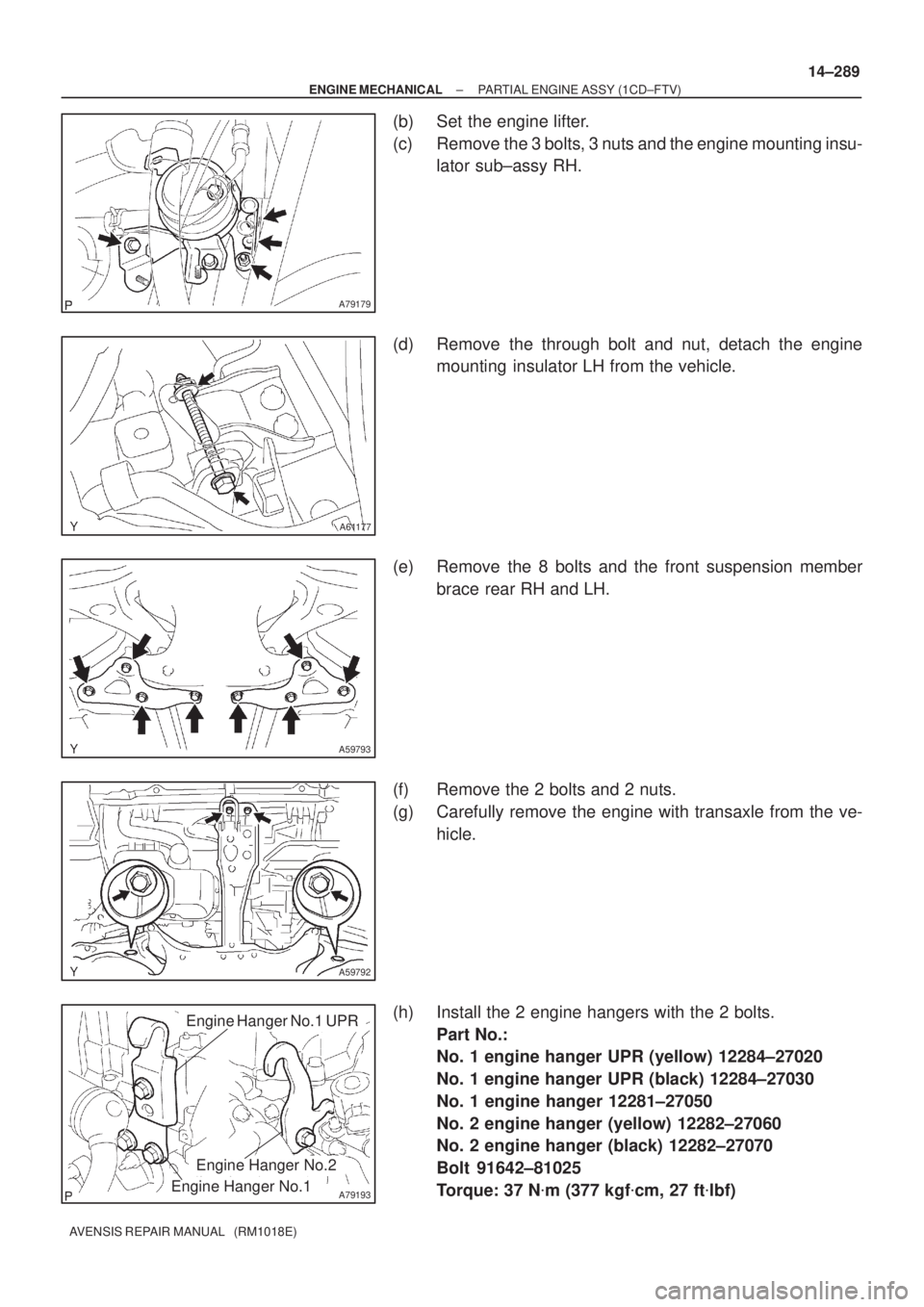
(b) Set the engine lifter.
(c) Remove the 3 bolts, 3 nuts and the engine mounting insu-
lator sub±assy RH.
(d) Remove the through bolt and nut, detach the engine
mounting insulator LH from the vehicle.
(e) Remove the 8 bolts and the front suspension member
brace rear RH and LH.
(f) Remove the 2 bolts and 2 nuts.
(g) Carefully remove the engine with transaxle from the ve-
hicle.
(h) Install the 2 engine hangers with the 2 bolts.
Part No.:
No. 1 engine hanger UPR (yellow) 12284±27020
No. 1 engine hanger UPR (black) 12284±27030
No. 1 engine hanger 12281±27050
No. 2 engine hanger (yellow) 12282±27060
No. 2 engine hanger (black) 12282±27070
Bolt 91642±81025
Torque: 37 N�m (377 kgf�cm, 27 ft�lbf)