Page 1990 of 5135
13070±01
A79168
A80112
A80113
A64328
2 to 7 mm0 to 5 mm
13±18
±
INTAKE INTERCOOLER ASSY(1CD±FTV)
AVENSIS REPAIR MANUAL (RM1018E)
INTERCOOLER ASSY(1CD±FTV)
REPLACEMENT
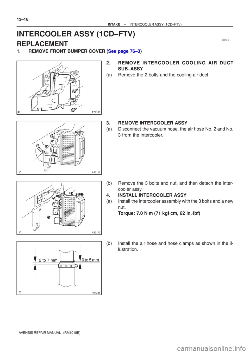
1.REMOVE FRONT BUMPER COVER (See page 76±3) 2. REMOVE INTERCOOLER COOLING AIR DUCTSUB±ASSY
(a) Remove the 2 bolts and the cooling air duct.
3. REMOVE INTERCOOLER ASSY
(a) Disconnect the vacuum hose, the air hose No. 2 and No. 3 from the intercooler.
(b) Remove the 3 bolts and nut, and then detach the inter- cooler assy.
4. INSTALL INTERCOOLER ASSY
(a) Install the intercooler assembly with the 3 bolts and a new nut.
Torque: 7.0 N �m (71 kgf �cm, 62 in. �lbf)
(b) Install the air hose and hose clamps as shown in the il- lustration.
Page 1991 of 5135
A64007
Front90
�
Clamp
Bolt
±
INTAKE INTERCOOLER ASSY(1CD±FTV)
13±19
AVENSIS REPAIR MANUAL (RM1018E)
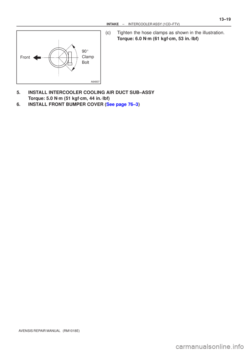
(c)Tighten the hose clamps as shown in the illustration.
Torque: 6.0 N �m (61 kgf �cm, 53 in. �lbf)
5.INSTALL INTERCOOLER COOLING AIR DUCT SUB±ASSY Torque: 5.0 N �m (51 kgf �cm, 44 in. �lbf)
6.INSTALL FRONT BUMPER COVER (See page 76±3)
Page 2368 of 5135
1509T±01
A78493
A78494
(c)
(d)
A78495
A78496
15±2
±
EXHAUST EXHAUST PIPE ASSY(1ZZ±FE/3ZZ±FE)
AVENSIS REPAIR MANUAL (RM1018E)
Removal & Installation and Disassembly & Reassembly
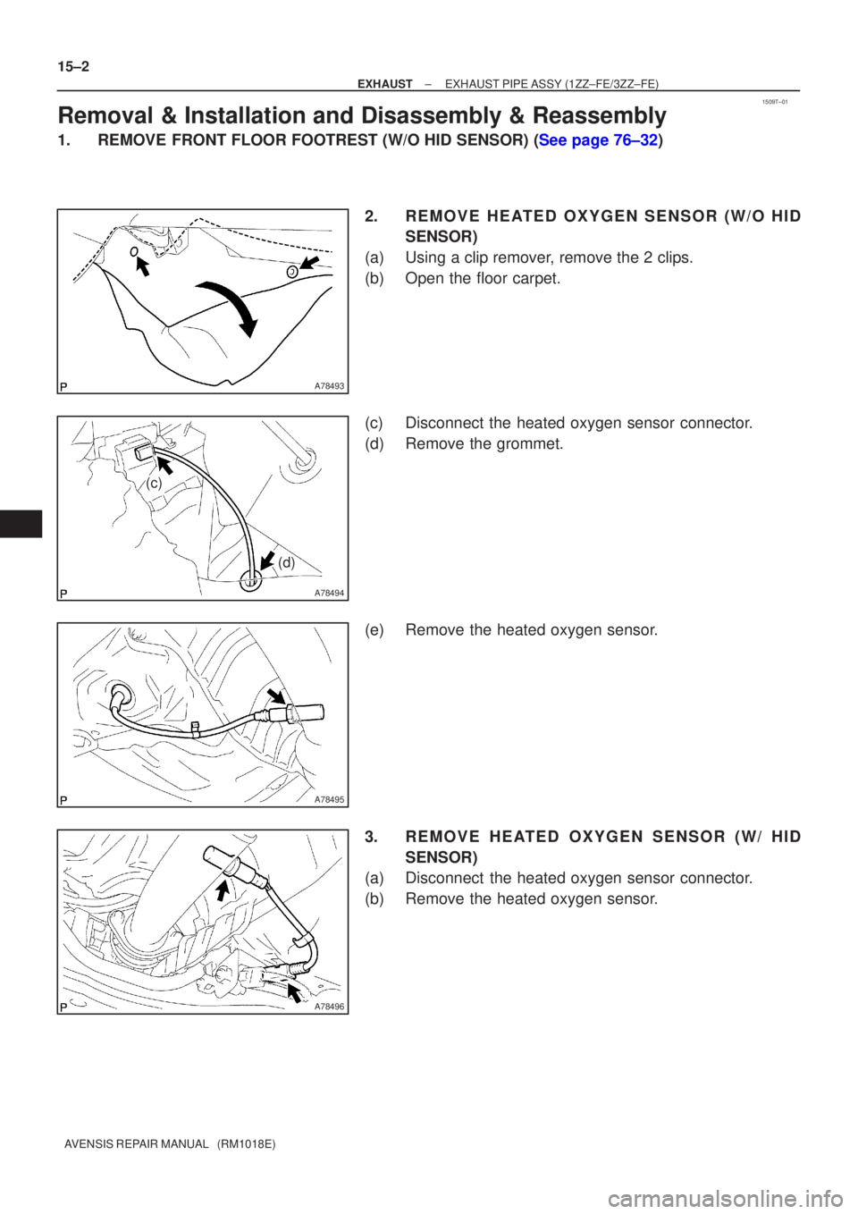
1.REMOVE FRONT FLOOR FOOTREST (W/O HID SENSOR) (See page 76±32) 2. REMOVE HEATED OXYGEN SENSOR (W/O HIDSENSOR)
(a) Using a clip remover, remove the 2 clips.
(b) Open the floor carpet.
(c) Disconnect the heated oxygen sensor connector.
(d) Remove the grommet.
(e) Remove the heated oxygen sensor.
3. REMOVE HEATED OXYGEN SENSOR (W/ HID SENSOR)
(a) Disconnect the heated oxygen sensor connector.
(b) Remove the heated oxygen sensor.
Page 2999 of 5135
550ZB±01
������������I35836
w/o Hot gas heater:
w/ Hot gas heater:
I35335
I35336
±
HEATER & AIR CONDITIONER W/RECEIVER CONDENSER ASSY
55±93
AVENSIS REPAIR MANUAL (RM1018E)
OVERHAUL
HINT:
COMPONENTS: See page 55±91
1.DISCHARGE REFRIGERANT FROM REFRIGERATION SYSTEM (See page 55±38)
SST 07110±58060 (07117±58080, 07117±58090, 07117±78050, 07117±88060, 07117±88070, 07117±88080)
2.REMOVE FRONT BUMPER COVER (See page 76±3)
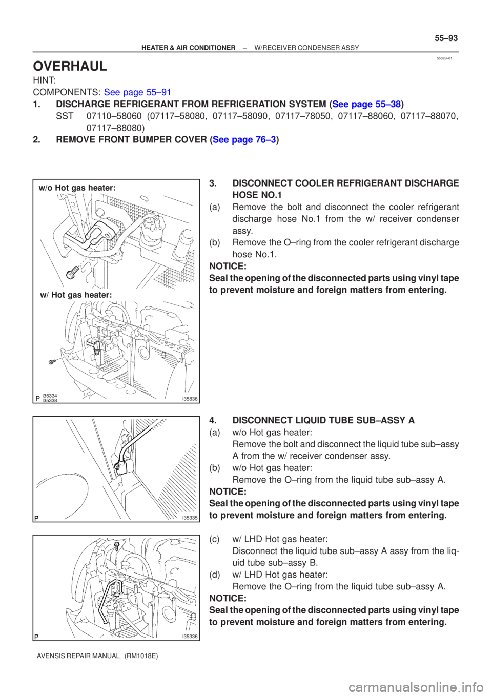
3. DISCONNECT COOLER REFRIGERANT DISCHARGEHOSE NO.1
(a) Remove the bolt and disconnect the cooler refrigerant discharge hose No.1 from the w/ receiver condenser
assy.
(b) Remove the O±ring from the cooler refrigerant discharge
hose No.1.
NOTICE:
Seal the opening of the disconnected parts using vinyl tape
to prevent moisture and foreign matters from entering.
4. DISCONNECT LIQUID TUBE SUB±ASSY A
(a) w/o Hot gas heater: Remove the bolt and disconnect the liquid tube sub±assy
A from the w/ receiver condenser assy.
(b) w/o Hot gas heater: Remove the O±ring from the liquid tube sub±assy A.
NOTICE:
Seal the opening of the disconnected parts using vinyl tape
to prevent moisture and foreign matters from entering.
(c) w/ LHD Hot gas heater: Disconnect the liquid tube sub±assy A assy from the liq-
uid tube sub±assy B.
(d) w/ LHD Hot gas heater: Remove the O±ring from the liquid tube sub±assy A.
NOTICE:
Seal the opening of the disconnected parts using vinyl tape
to prevent moisture and foreign matters from entering.
Page 3005 of 5135
������������I35837
w/o Hot gas heater:
w/ Hot gas heater:
±
HEATER & AIR CONDITIONER W/RECEIVER CONDENSER ASSY
55±99
AVENSIS REPAIR MANUAL (RM1018E)
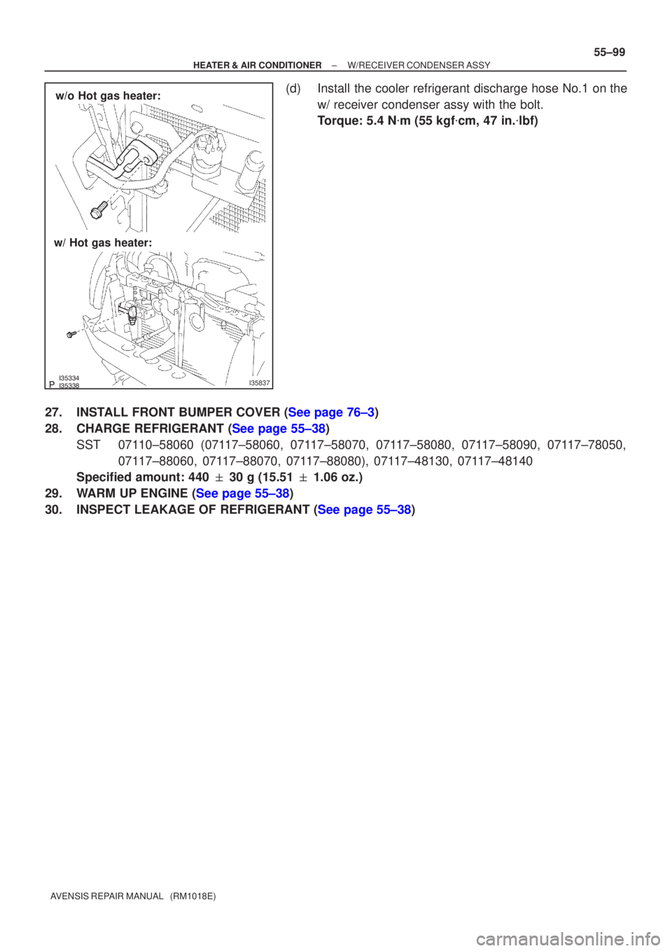
(d) Install the cooler refrigerant discharge hose No.1 on the
w/ receiver condenser assy with the bolt.
Torque: 5.4 N �m (55 kgf �cm, 47 in. �lbf)
27.INSTALL FRONT BUMPER COVER (See page 76±3)
28.CHARGE REFRIGERANT (See page 55±38) SST 07110±58060 (07117±58060, 07117±58070, 07117±58080, 07117±58090, 07117±78050, 07117±88060, 07117±88070, 07117±88080), 07117±48130, 07117±48140
Specified amount: 440 � 30 g (15.51 � 1.06 oz.)
29.WARM UP ENGINE (See page 55±38)
30.INSPECT LEAKAGE OF REFRIGERANT (See page 55±38)
Page 3010 of 5135
600K8±01
H42769
60±68
±
SUPPLEMENTAL RESTRAINT SYSTEM AIR BAG SENSOR REAR LH
AVENSIS REPAIR MANUAL (RM1018E)
REPLACEMENT
HINT:
Replacement procedure of the RH side is the same as that for the LH side.
1.PRECAUTION (See page 60±1)
2.DISCONNECT BATTERY NEGATIVE TERMINAL (See page 60±1)
3.REMOVE REAR DOOR SCUFF PLATE LH (See page 76±36)
4.REMOVE REAR SEAT CUSHION ASSEMBLY (SEDAN MODELS) (See page 76±36)
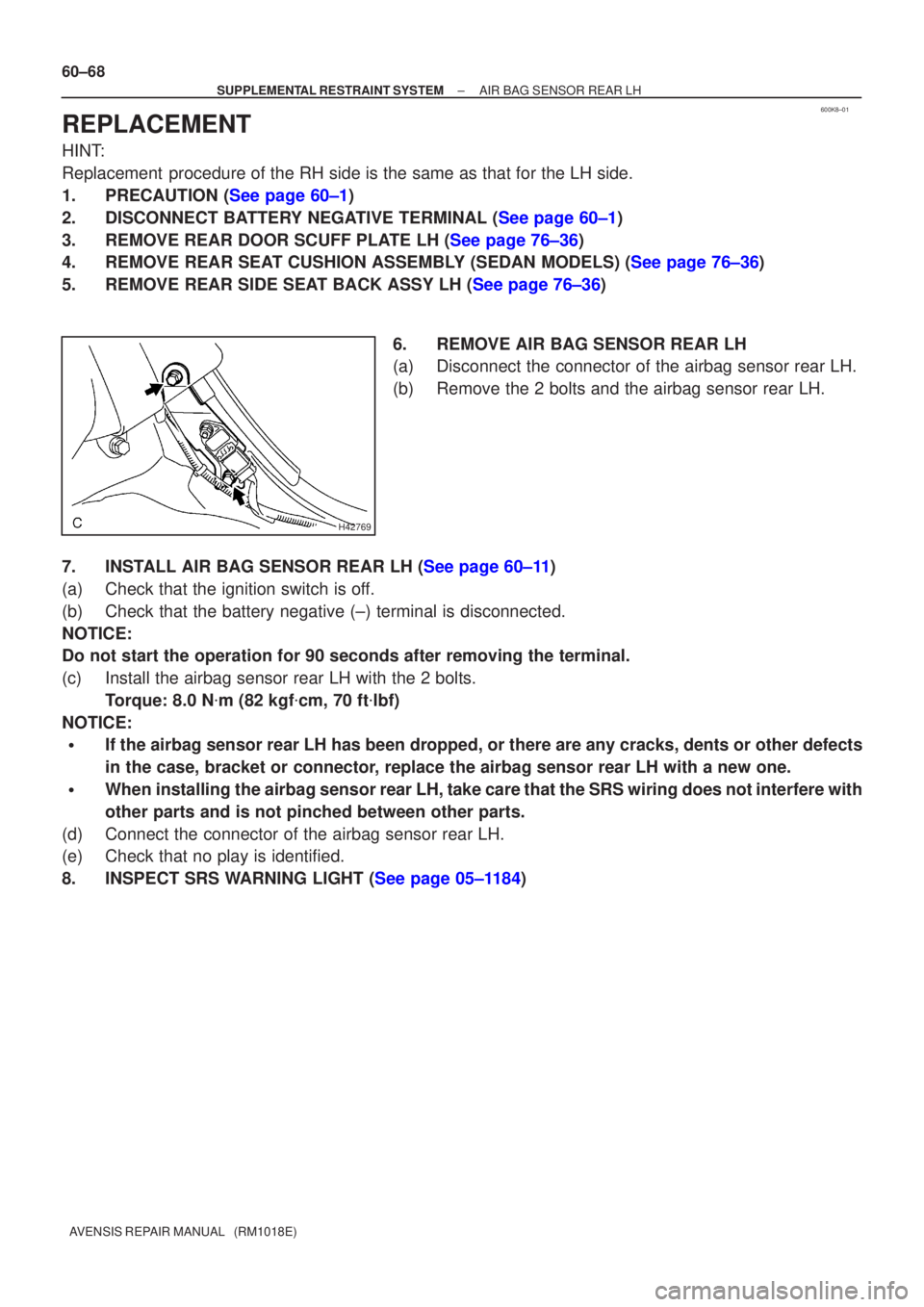
5.REMOVE REAR SIDE SEAT BACK ASSY LH (See page 76±36) 6. REMOVE AIR BAG SENSOR REAR LH
(a) Disconnect the connector of the airbag sensor rear LH.
(b) Remove the 2 bolts and the airbag sensor rear LH.
7.INSTALL AIR BAG SENSOR REAR LH (See page 60±11)
(a) Check that the ignition switch is off.
(b) Check that the battery negative (±) terminal is disconnected.
NOTICE:
Do not start the operation for 90 seconds after removing the terminal.
(c) Install the airbag sensor rear LH with the 2 bolts. Torque: 8.0 N �m (82 kgf �cm, 70 ft �lbf)
NOTICE:
�If the airbag sensor rear LH has been dropped, or there are any cracks, \
dents or other defects
in the case, bracket or connector, replace the airbag sensor rear LH with a new one.
�When installing the airbag sensor rear LH, take care that the SRS wiring does not interfere \
with
other parts and is not pinched between other parts.
(d) Connect the connector of the airbag sensor rear LH.
(e) Check that no play is identified.
8.INSPECT SRS WARNING LIGHT (See page 05±1184)
Page 3012 of 5135
600A7±03
H42767
60±66
±
SUPPLEMENTAL RESTRAINT SYSTEM SIDE AIR BAG SENSOR ASSY LH
AVENSIS REPAIR MANUAL (RM1018E)
REPLACEMENT
HINT:
Replacement procedure of the RH side is the same as that for with LH side.
1.PRECAUTION (See page 60±1)
2.DISCONNECT BATTERY NEGATIVE TERMINAL (See page 60±1)
3.REMOVE FRONT DOOR SCUFF PLATE LH (See page 76±36)
4.REMOVE REAR DOOR SCUFF PLATE LH (See page 76±36)
5.REMOVE FRONT DOOR WEATHERSTRIP LH (See page 76±36)
6.REMOVE REAR DOOR WEATHERSTRIP LH (See page 76±36)
7.REMOVE CENTER PILLAR GARNISH LOWER LH (See page 76±36)
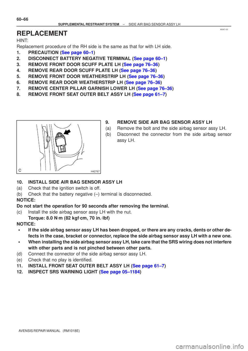
8.REMOVE FRONT SEAT OUTER BELT ASSY LH (See page 61±7) 9. REMOVE SIDE AIR BAG SENSOR ASSY LH
(a) Remove the bolt and the side airbag sensor assy LH.
(b) Disconnect the connector from the side airbag sensorassy LH.
10. INSTALL SIDE AIR BAG SENSOR ASSY LH
(a) Check that the ignition switch is off.
(b) Check that the battery negative (±) terminal is disconnected.
NOTICE:
Do not start the operation for 90 seconds after removing the terminal.
(c) Install the side airbag sensor assy LH with the nut. Torque: 8.0 N �m (82 kgf �cm, 70 in. �lbf)
NOTICE:
�If the side airbag sensor assy LH has been dropped, or there are any cra\
cks, dents or other de-
fects in the case, bracket or connector, replace the side airbag sensor assy LH with a new one.
�When installing the side airbag sensor assy LH, take care that the SRS wiring\
does not interfere
with other parts and is not pinched between other parts.
(d) Connect the connector of the side airbag sensor assy LH.
(e) Check that no play is identified.
11.INSTALL FRONT SEAT OUTER BELT ASSY LH (See page 61±7)
12.INSPECT SRS WARNING LIGHT (See page 05±1184)
Page 3032 of 5135
6009Y±02
H40004
SST(s)
H40005
Battery
SST(s)
±
SUPPLEMENTAL RESTRAINT SYSTEM CURTAIN SHIELD AIR BAG ASSY LH
60±41
AVENSIS REPAIR MANUAL (RM1018E)
DISPOSAL
HINT:
�Disposal procedure of the RH side is the same as that for the LH side.
�When scrapping a vehicle equipped with SRS or disposing of the curtain shield airbag assy LH, be sure
to deploy the airbag first in accordance with the procedure described belo\
w. If any abnormality occurs
with the airbag deployment, contact the SERVICE DEPT. of TOYOTA MOTOR SALES, U.S.A., INC.
CAUTION:
�Never dispose of the curtain shield airbag assy LH
that has an undeployed airbag.
�The airbag produces an exploding sound when it is
deployed, so perform the operation outdoors and
where it will not create a nuisance to nearby resi-
dents.
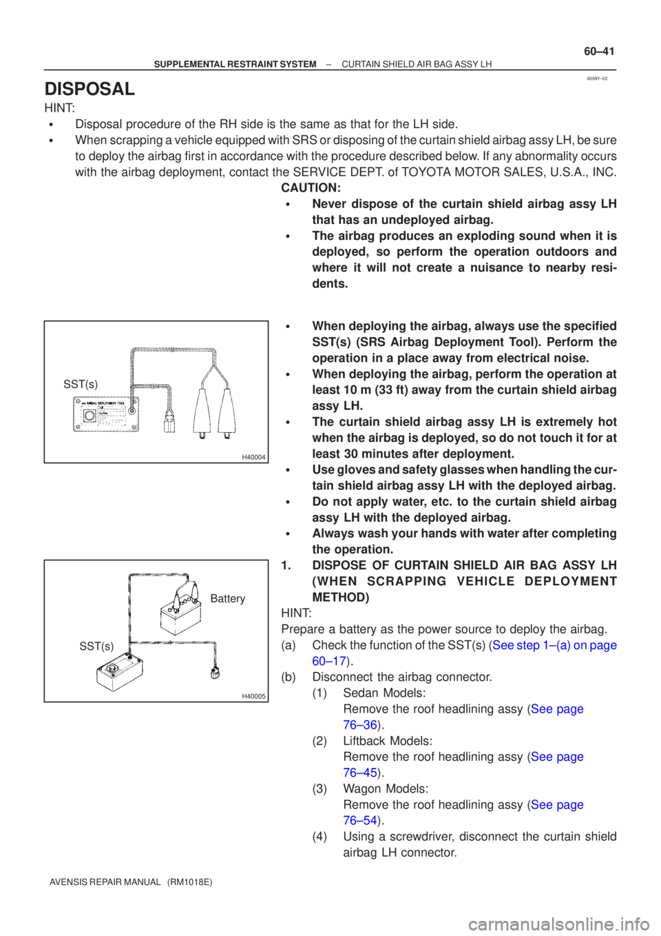
�When deploying the airbag, always use the specified
SST(s) (SRS Airbag Deployment Tool). Perform the
operation in a place away from electrical noise.
�When deploying the airbag, perform the operation at
least 10 m (33 ft) away from the curtain shield airbag
assy LH.
�The curtain shield airbag assy LH is extremely hot
when the airbag is deployed, so do not touch it for at
least 30 minutes after deployment.
�Use gloves and safety glasses when handling the cur-
tain shield airbag assy LH with the deployed airbag.
�Do not apply water, etc. to the curtain shield airbag
assy LH with the deployed airbag.
�Always wash your hands with water after completing
the operation.
1. DISPOSE OF CURTAIN SHIELD AIR BAG ASSY LH (WHEN SCRAPPING VEHICLE DEPLOYMENT
METHOD)
HINT:
Prepare a battery as the power source to deploy the airbag.
(a)Check the function of the SST(s) (See step 1±(a) on page
60±17).
(b) Disconnect the airbag connector.
(1) Sedan Models:Remove the roof headlining assy (See page
76±36).
(2) Liftback Models: Remove the roof headlining assy (See page
76±45).
(3) Wagon Models: Remove the roof headlining assy (See page
76±54).
(4) Using a screwdriver, disconnect the curtain shield airbag LH connector.