Page 5104 of 5135
600UO–01
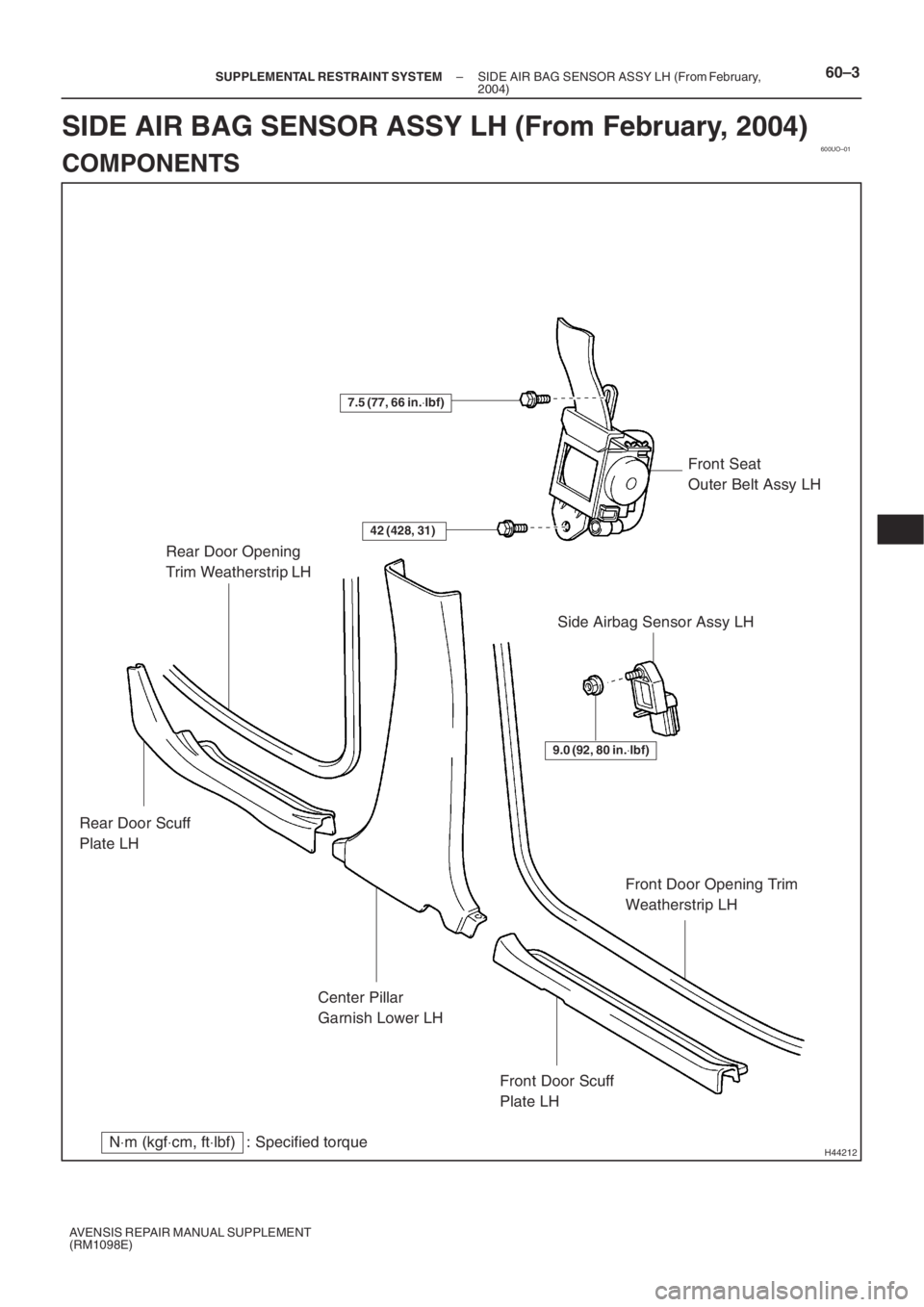
H44212N⋅m (kgf⋅cm, ft⋅lbf) : Specified torque Rear Door Opening
Trim Weatherstrip LH
Rear Door Scuff
Plate LH
Center Pillar
Garnish Lower LH
Front Door Scuff
Plate LHFront Door Opening Trim
Weatherstrip LHFront Seat
Outer Belt Assy LH
9.0 (92, 80 in.⋅lbf)
Side Airbag Sensor Assy LH
42 (428, 31)
7.5 (77, 66 in.⋅lbf)
– SUPPLEMENTAL RESTRAINT SYSTEMSIDE AIR BAG SENSOR ASSY LH (From February,
2004)60–3
AVENSIS REPAIR MANUAL SUPPLEMENT
(RM1098E)
SIDE AIR BAG SENSOR ASSY LH (From February, 2004)
COMPONENTS
Page 5110 of 5135
A95728
A95729
Connecting Bearing Cap: Connecting Bearing:
TAIHO Mark Lot. Number Mark
TAIHO Made
FEDERAL MOGUL
/GLYCO Made
MarkMark
14–54
– ENGINE MECHANICALCYLINDER BLOCK ASSY (1ZZ–FE/3ZZ–FE)
1ZZ–FE,3ZZ–FE ENGINE REPAIR MANUAL
(RM1099E)
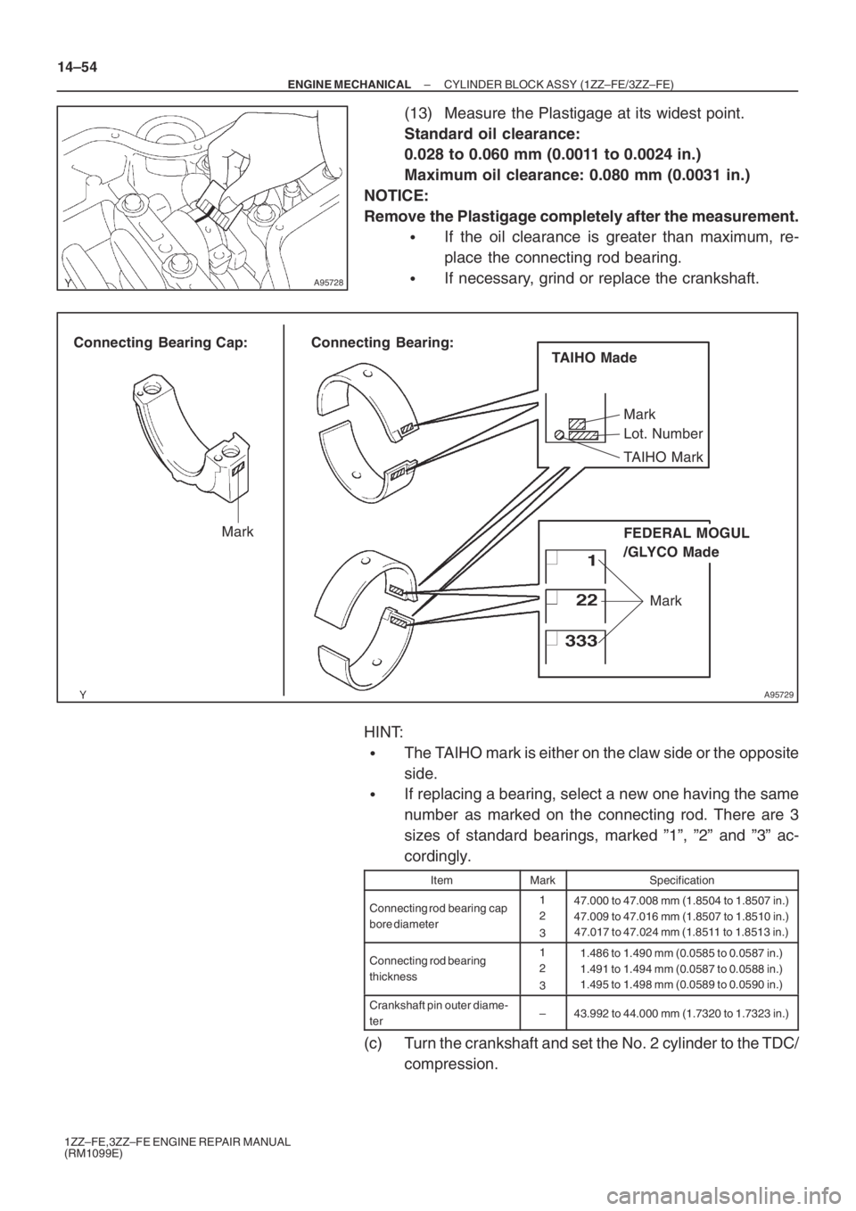
(13) Measure the Plastigage at its widest point.
Standard oil clearance:
0.028 to 0.060 mm (0.0011 to 0.0024 in.)
Maximum oil clearance: 0.080 mm (0.0031 in.)
NOTICE:
Remove the Plastigage completely after the measurement.
�If the oil clearance is greater than maximum, re-
place the connecting rod bearing.
�If necessary, grind or replace the crankshaft.
HINT:
�The TAIHO mark is either on the claw side or the opposite
side.
�If replacing a bearing, select a new one having the same
number as marked on the connecting rod. There are 3
sizes of standard bearings, marked ”1”, ”2” and ”3” ac-
cordingly.
ItemMarkSpecification
Connecting rod bearing cap
bore diameter1
2
347.000 to 47.008 mm (1.8504 to 1.8507 in.)
47.009 to 47.016 mm (1.8507 to 1.8510 in.)
47.017 to 47.024 mm (1.8511 to 1.8513 in.)
Connecting rod bearing
thickness1
2
31.486 to 1.490 mm (0.0585 to 0.0587 in.)
1.491 to 1.494 mm (0.0587 to 0.0588 in.)
1.495 to 1.498 mm (0.0589 to 0.0590 in.)
Crankshaft pin outer diame-
ter–43.992 to 44.000 mm (1.7320 to 1.7323 in.)
(c) Turn the crankshaft and set the No. 2 cylinder to the TDC/
compression.
Page 5113 of 5135
A01160
A95729
Connecting Bearing Cap: Connecting Bearing:
TAIHO Mark Lot. Number Mark
TAIHO Made
FEDERAL MOGUL
/GLYCO Made
MarkMark
– ENGINE MECHANICALCYLINDER BLOCK ASSY (1ZZ–FE/3ZZ–FE)
14–57
1ZZ–FE,3ZZ–FE ENGINE REPAIR MANUAL
(RM1099E)
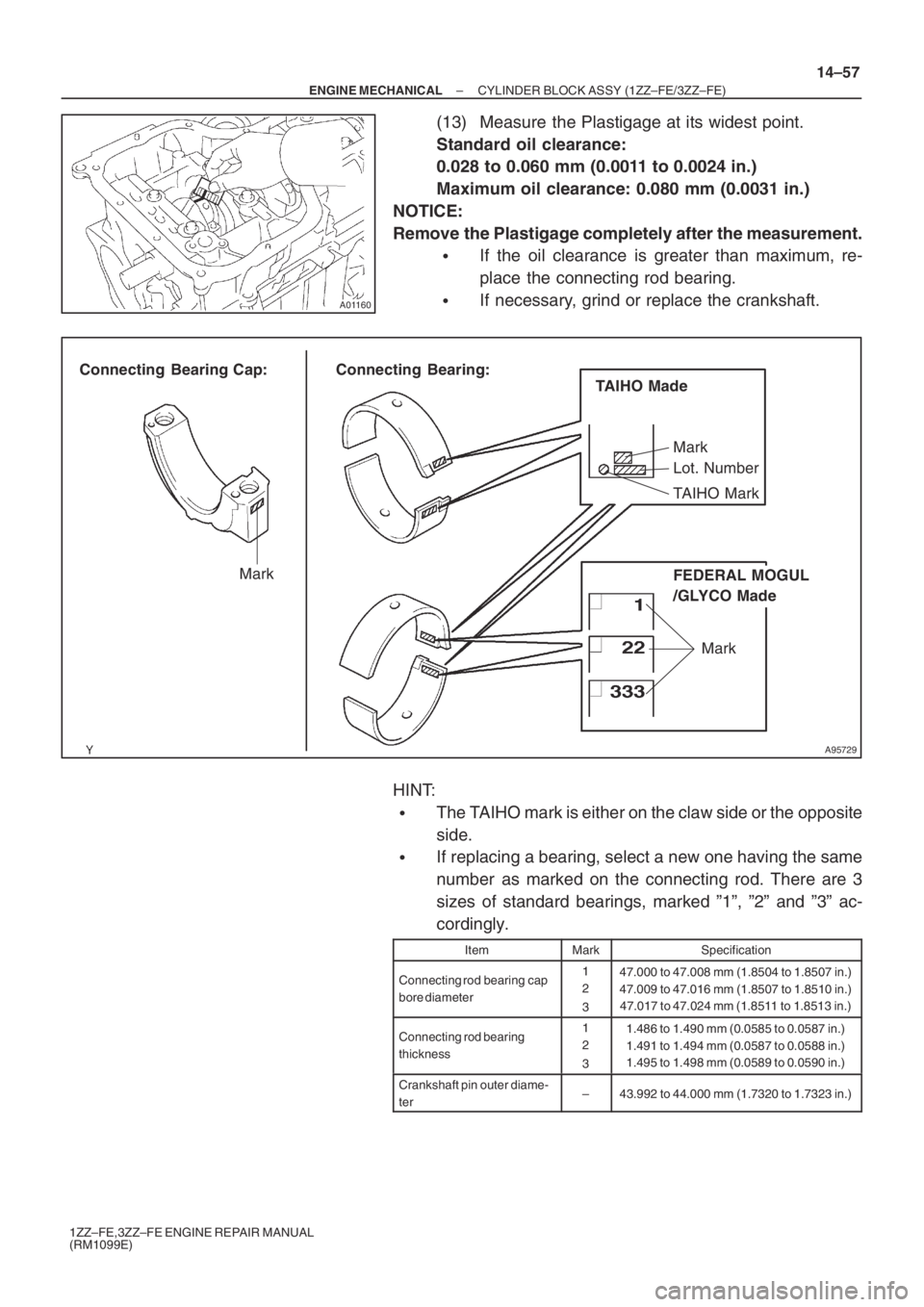
(13) Measure the Plastigage at its widest point.
Standard oil clearance:
0.028 to 0.060 mm (0.0011 to 0.0024 in.)
Maximum oil clearance: 0.080 mm (0.0031 in.)
NOTICE:
Remove the Plastigage completely after the measurement.
�If the oil clearance is greater than maximum, re-
place the connecting rod bearing.
�If necessary, grind or replace the crankshaft.
HINT:
�The TAIHO mark is either on the claw side or the opposite
side.
�If replacing a bearing, select a new one having the same
number as marked on the connecting rod. There are 3
sizes of standard bearings, marked ”1”, ”2” and ”3” ac-
cordingly.
ItemMarkSpecification
Connecting rod bearing cap
bore diameter1
2
347.000 to 47.008 mm (1.8504 to 1.8507 in.)
47.009 to 47.016 mm (1.8507 to 1.8510 in.)
47.017 to 47.024 mm (1.8511 to 1.8513 in.)
Connecting rod bearing
thickness1
2
31.486 to 1.490 mm (0.0585 to 0.0587 in.)
1.491 to 1.494 mm (0.0587 to 0.0588 in.)
1.495 to 1.498 mm (0.0589 to 0.0590 in.)
Crankshaft pin outer diame-
ter–43.992 to 44.000 mm (1.7320 to 1.7323 in.)
Page 5127 of 5135
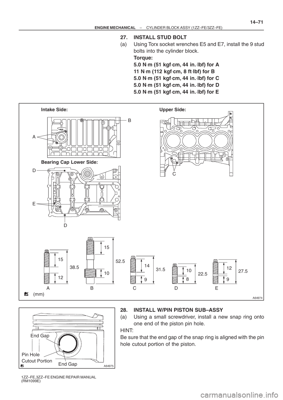
A64974
Intake Side:
Bearing Cap Lower Side:Upper Side:
A
D
E
DC B
ABCDE
(mm)15
1238.515
1052.5
14
931.512
927.5 10
822.5
A64975
End Gap
End Gap
Pin Hole
Cutout Portion
– ENGINE MECHANICALCYLINDER BLOCK ASSY (1ZZ–FE/3ZZ–FE)
14–71
1ZZ–FE,3ZZ–FE ENGINE REPAIR MANUAL
(RM1099E)
27. INSTALL STUD BOLT
(a) Using Torx socket wrenches E5 and E7, install the 9 stud
bolts into the cylinder block.
Torque:
5.0 N⋅m (51 kgf⋅cm, 44 in.⋅lbf) for A
11 N⋅m (112 kgf⋅cm, 8 ft⋅lbf) for B
5.0 N⋅m (51 kgf⋅cm, 44 in.⋅lbf) for C
5.0 N⋅m (51 kgf⋅cm, 44 in.⋅lbf) for D
5.0 N⋅m (51 kgf⋅cm, 44 in.⋅lbf) for E
28. INSTALL W/PIN PISTON SUB–ASSY
(a) Using a small screwdriver, install a new snap ring onto
one end of the piston pin hole.
HINT:
Be sure that the end gap of the snap ring is aligned with the pin
hole cutout portion of the piston.
Page 5128 of 5135
A01187
A64976
Front
Mark
A96654
End Gap
End Gap
Pin Hole
Cutout Portion
A62811
Cord Mark
Piston Ring
Expander
14–72
– ENGINE MECHANICALCYLINDER BLOCK ASSY (1ZZ–FE/3ZZ–FE)
1ZZ–FE,3ZZ–FE ENGINE REPAIR MANUAL
(RM1099E)
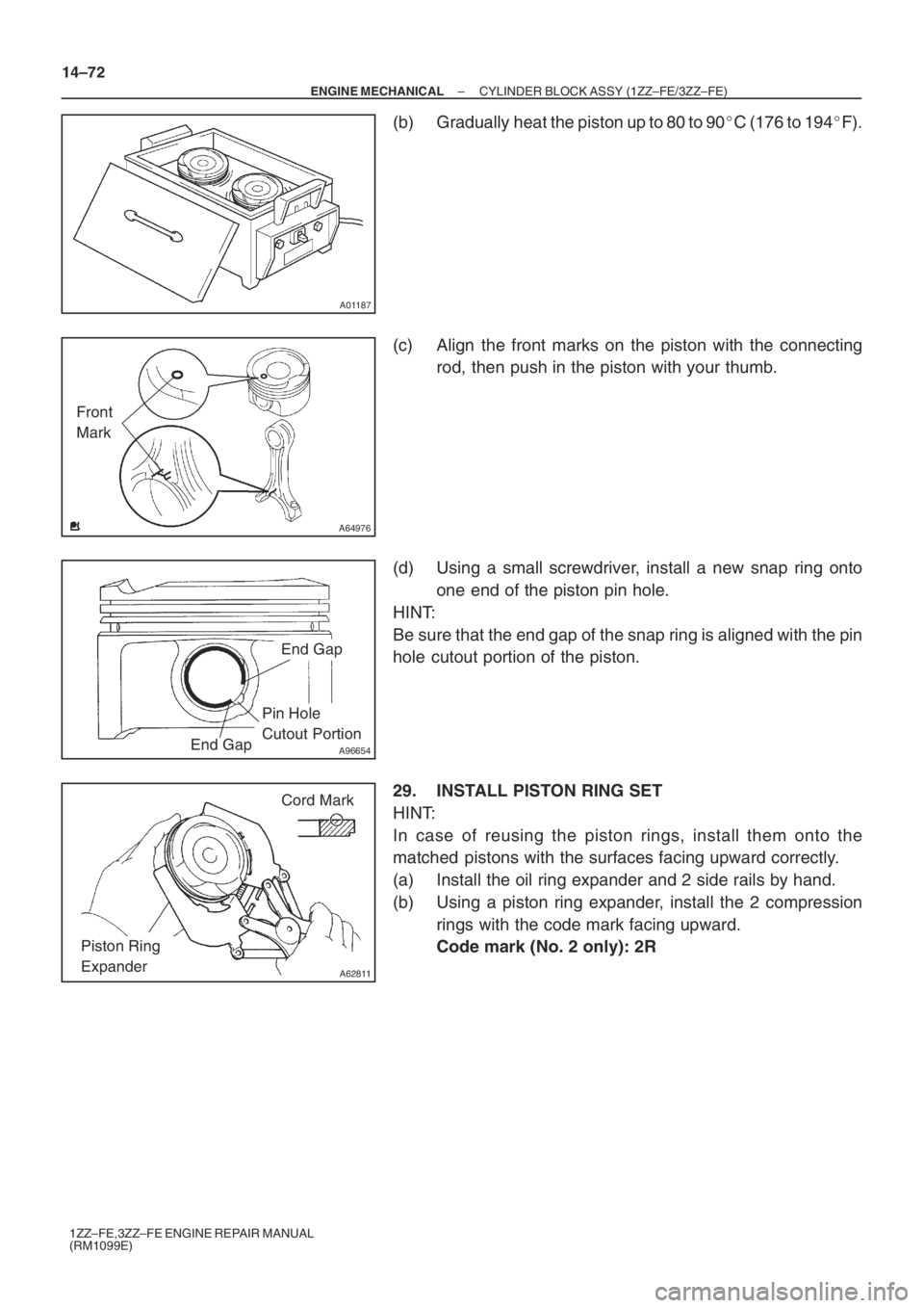
(b) Gradually heat the piston up to 80 to 90�C (176 to 194�F).
(c) Align the front marks on the piston with the connecting
rod, then push in the piston with your thumb.
(d) Using a small screwdriver, install a new snap ring onto
one end of the piston pin hole.
HINT:
Be sure that the end gap of the snap ring is aligned with the pin
hole cutout portion of the piston.
29. INSTALL PISTON RING SET
HINT:
In case of reusing the piston rings, install them onto the
matched pistons with the surfaces facing upward correctly.
(a) Install the oil ring expander and 2 side rails by hand.
(b) Using a piston ring expander, install the 2 compression
rings with the code mark facing upward.
Code mark (No. 2 only): 2R
Page 5129 of 5135
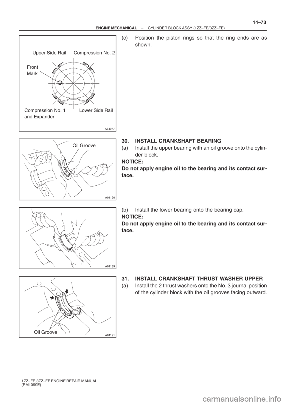
A64977
Upper Side Rail
Front
MarkCompression No. 2
Lower Side Rail Compression No. 1
and Expander
A01190
Oil Groove
A01189
A01191Oil Groove
– ENGINE MECHANICALCYLINDER BLOCK ASSY (1ZZ–FE/3ZZ–FE)
14–73
1ZZ–FE,3ZZ–FE ENGINE REPAIR MANUAL
(RM1099E)
(c) Position the piston rings so that the ring ends are as
shown.
30. INSTALL CRANKSHAFT BEARING
(a) Install the upper bearing with an oil groove onto the cylin-
der block.
NOTICE:
Do not apply engine oil to the bearing and its contact sur-
face.
(b) Install the lower bearing onto the bearing cap.
NOTICE:
Do not apply engine oil to the bearing and its contact sur-
face.
31. INSTALL CRANKSHAFT THRUST WASHER UPPER
(a) Install the 2 thrust washers onto the No. 3 journal position
of the cylinder block with the oil grooves facing outward.