Page 1236 of 5135

(b) Clear the DTCs.
(1) Connect the hand±held tester to the DLC3.
(2) Turn the ignition switch to the ON positio")
± DIAGNOSTICSSUPPLEMENTAL RESTRAINT SYSTEM
05±1187
AVENSIS REPAIR MANUAL (RM1018E)
(b) Clear the DTCs.
(1) Connect the hand±held tester to the DLC3.
(2) Turn the ignition switch to the ON position.
(3) Clear the DTCs by following the prompts on the tester screen.
HINT:
Please refer to the hand±held tester operation's manual for further details.
5. RELEASE METHOD OF ACTIVATION PREVENTION MECHANISM
(a) The activation prevention mechanism is built in the connector for the squib circuit of the SRS.
As explained in the troubleshooting later, insert a paper with the same thickness as the male terminal
between the terminal and the short spring to release it (Refer to illustrations on next 2 pages).
CAUTION:
Never release the activation prevention mechanism on the squib connector.
NOTICE:
�Do not release the activation prevention mechanism unless specially directed by the trouble-
shooting procedure.
�To prevent the terminal and the short spring from damage, always use a paper with the same
thickness as the male terminals.
Page 1240 of 5135
050YF±18
±
DIAGNOSTICS SUPPLEMENTAL RESTRAINT SYSTEM
05±1181
AVENSIS REPAIR MANUAL (RM1018E)
SUPPLEMENTAL RESTRAINT SYSTEM
HOW TO PROCEED WITH TROUBLESHOOTING
The hand±held tester can be used at step 3, 5, 8, 9.
1VEHICLE BROUGHT TO WORKSHOP
2CUSTOMER PROBLEM ANALYSIS (See page 05±1183)
3DTC CHECK (Present and Past DTC) (See page 05±1184)
DTC IS OUTPUT: Go to step 4
DTC IS NOT OUTPUT: Go to step 11
4THE DTCS CHART (See page 05±1190)
5CIRCUIT INSPECTION (See page 05±1198 to 05±1374)
MALFUNCTION CODE IS OUTPUT: Go to step 6
NORMAL CODE IS OUTPUT: Go to step 11
6 IDENTIFICATION OF PROBLEM
7 REPAIR
8CLEAR THE DTCS (Present and Past DTC) (See page 05±1184)
9DTC CHECK (See page 05±1184)
DTC CODE IS NOT OUTPUT: Go to step 10
DTC CODE IS OUTPUT: Go to step 4
Page 1242 of 5135
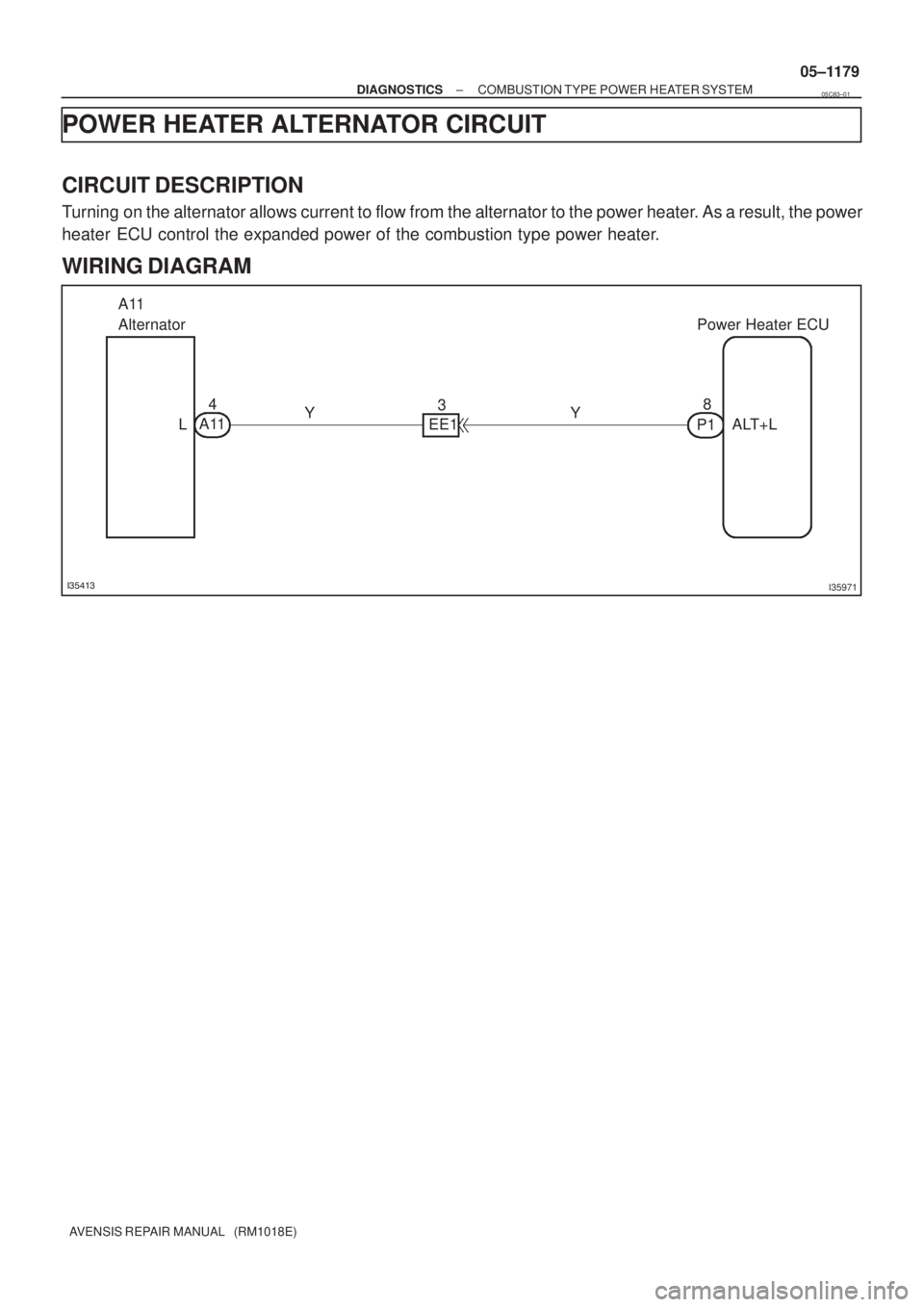
������I35971
A11
AlternatorPower Heater ECU
L EE1
P1ALT+L A114
38
YY
± DIAGNOSTICSCOMBUSTION TYPE POWER HEATER SYSTEM
05±1179
AVENSIS REPAIR MANUAL (RM1018E)
POWER HEATER ALTERNATOR CIRCUIT
CIRCUIT DESCRIPTION
Turning on the alternator allows current to flow from the alternator to the power heater. As a result, the power
heater ECU control the expanded power of the combustion type power heater.
WIRING DIAGRAM
05C83±01
Page 1243 of 5135
I37735
ALT+LL
1 23 45 67 8
1234
P1
A11
05±1180
±
DIAGNOSTICS COMBUSTION TYPE POWER HEATER SYSTEM
AVENSIS REPAIR MANUAL (RM1018E)
1CHECK WIRE HARNESS(POWER HEATER ECU ± ALTERNATOR)
(a)Check for an open or short circuit in harness and connec- tor between terminal ALT+L of power heater ECU and ter-
minal L of alternator (See page 01±32).
NG REPAIR OR REPLACE WIRE HARNESS
OK
2 CHECK AND REPLACE GENERATOR W/CLUTCH PULLEY
NG REPAIR OR REPLACE GENERATOR W/CLUTCH PULLEY
OK
REPAIR OR REPLACE POWER HEATER ECU
Page 1244 of 5135
I35412
F17
Fuel Pump
M
21L
W±B
ECP12
F/P Power Heater ECU 05±1176
± DIAGNOSTICSCOMBUSTION TYPE POWER HEATER SYSTEM
AVENSIS REPAIR MANUAL (RM1018E)
POWER HEATER FUEL PUMP CIRCUIT
CIRCUIT DESCRIPTION
When the power heater switch is turned on, the fuel pump receives the drive voltage from the power heater
ECU, causing the combustion type power heater to operate.
WIRING DIAGRAM
05C82±01
Page 1245 of 5135
I37732
1 23 4
5 67 8
F/P
P1
I37734
12 F17
I37734
12F17
±
DIAGNOSTICS COMBUSTION TYPE POWER HEATER SYSTEM
05±1177
AVENSIS REPAIR MANUAL (RM1018E)
1CHECK WIRE HARNESS(POWER HEATER ECU ± BODY GROUND)
(a)Check for short circuit in harness and connector between
terminal F/P of power heater ECU and body ground
(See page 01±32).
NG REPAIR OR REPLACE WIRE HARNESS
OK
2 CHECK WIRE HARNESS(POWER HEATER ECU ± POWER HEATER FUEL PUMP)
(a) Check for an open or short circuit in harness and connec- tor betwen terminal 1 of power heater ECU and power
heater fuel pump (See page 01±32).
NG REPAIR OR REPLACE WIRE HARNESS
OK
3 CHECK WIRE HARNESS(POWER HEATER FUEL PUMP ± BODY GROUND)
(a) Check for an open circuit in harness and connector be- tween terminal 2 of power heater fuel pump and body
ground
(See page 01±32).
NG REPAIR OR REPLACE WIRE HARNESS
OK
Page 1246 of 5135
I36139
F17
05±1178
± DIAGNOSTICSCOMBUSTION TYPE POWER HEATER SYSTEM
AVENSIS REPAIR MANUAL (RM1018E)
4 INSPECT POWER HEATER FUEL PUMP
(a) Connect the positive (+) lead from the battery to terminal
1 and negative (±) to terminal 2 with the power heater
turned on and check the pressure of the hose by hand.
Standard: The pressure is applied to the hose.
NG REPAIR OR REPLACE POWER HEATER FUEL
PUMP
OK
PROCEED TO NEXT CIRCUIT INSPECTION SHOWN IN PROBLEM SYMPTOMS TABLE
Page 1247 of 5135
I36132
Center J/BP5
Power Heater SWPower Heater ECU
CB1
CK12
R±W G±Y G±Y
IE612
P13
SW
W±B
R±W36IG IN
2 E
Driver Side J/B
B±L
DN
DH5 1 IG1 Relay HTR
DC
DA9 6
DH1W±B
AM1
I13
Ignition SW
1 IG1 AM1 3G±R
Engine Room R/B No.3
ALT
ED11
B±L W
33
21
B
FL MAIN
Battery
IJ IKA
J15
J/C 53
12
G±Y
± DIAGNOSTICSCOMBUSTION TYPE POWER HEATER SYSTEM
05±1173
AVENSIS REPAIR MANUAL (RM1018E)
POWER HEATER SWITCH CIRCUIT
CIRCUIT DESCRIPTION
When the power heter switch is turned on, the power heater ECU sends the drive signal to the fuel pump,
causing the combustion type power heater to operate.
WIRING DIAGRAM
05C81±01

SUPPLEMENTAL RESTRAINT SYSTEM
HOW TO PROCEED WITH TROUBLESHOOTING
The hand±held tester can be used at")

1CHECK WIRE HARNESS(POWER HEATER ECU ± ALTERNATOR)
(a)Check fo")

POWER HEATER FUEL PUMP CIRCUIT
CIRCUIT DESCRIPTI")

1CHECK WIRE HARNESS(POWER HEATER ECU ± BODY GR")

4 INSPECT POWER HEATER FUEL PUMP
(a) Connect the positive (+) lead from the battery to terminal")
