Page 1288 of 5135

DTC B0136/74 OPEN IN P/T SQU")
������������H40056
P/T Squib LHPL±
PL+ Airbag
Sensor
Assy
CenterFloor Wire
A
B
C
D
±
DIAGNOSTICS SUPPLEMENTAL RESTRAINT SYSTEM
05±1273
AVENSIS REPAIR MANUAL (RM1018E)
DTC B0136/74 OPEN IN P/T SQUIB (LH) CIRCUIT
CIRCUIT DESCRIPTION
The P/T squib LH circuit consists of the airbag sensor assy center and the \
front seat outer belt assy LH (seat
belt pretensioner LH).
This circuit actuates the SRS to deploy when the SRS deployment conditio\
ns are fulfilled.
DTC B0136/74 is recorded when an open circuit is detected in the P/T squ\
ib LH circuit.
DTC No.DTC Detecting ConditionTrouble Area
B0136/74
�Open circuit in PL+ wire harness or PL± wire harness of P/T
squib LH
� P/T squib LH malfunction
� Airbag sensor assy center malfunction�Front seat outer belt assy LH (P/T squib LH)
� Airbag sensor assy center
� Floor wire
WIRING DIAGRAM
See page 05±1270.
INSPECTION PROCEDURE
1 CHECK FLOOR WIRE(P/T SQUIB LH CIRCUIT)
(a) Turn the ignition switch to the LOCK position.
(b) Disconnect the negative (±) terminal cable from the bat-
tery, and wait for at least 90 seconds.
(c) Disconnect the connectors from the airbag sensor assy center and the front seat outer belt assy LH.
(d) Measure the resistance between PL+ and PL± of the con- nector ºCº.
OK:
Resistance: Below 1 �
NG REPAIR OR REPLACE FLOOR WIRE
OK
056MA±03
Page 1291 of 5135
H01454
Airbag Sensor Assy Center
P16
P/T Squib LH
A26 PL+ Y±B
A26PL± Y 1
28
7 05±1270
± DIAGNOSTICSSUPPLEMENTAL RESTRAINT SYSTEM
AVENSIS REPAIR MANUAL (RM1018E)
DTC B0135/73 SHORT IN P/T SQUIB (LH) CIRCUIT
CIRCUIT DESCRIPTION
The P/T squib LH circuit consists of the airbag sensor assy center and the front seat outer belt assy LH (seat
belt pretensioner LH).
This circuit actuates the SRS to deploy when the SRS deployment conditions are fulfilled.
DTC B0135/73 is recorded when a short circuit is detected in the P/T squib LH circuit.
DTC No.DTC Detecting ConditionTrouble Area
B0135/73
�Short circuit between PL+ wire harness and PL± wire harness
of P/T squib LH
�P/T squib LH malfunction
�Airbag sensor assy center malfunction�Front seat outer belt assy LH (P/T squib LH)
�Airbag sensor assy center
�Floor wire
WIRING DIAGRAM
056M9±03
Page 1292 of 5135
������������H40056
P/T Squib LHPL±
PL+ Airbag
Sensor
Assy
CenterFloor Wire
A
B
C
D
±
DIAGNOSTICS SUPPLEMENTAL RESTRAINT SYSTEM
05±1271
AVENSIS REPAIR MANUAL (RM1018E)
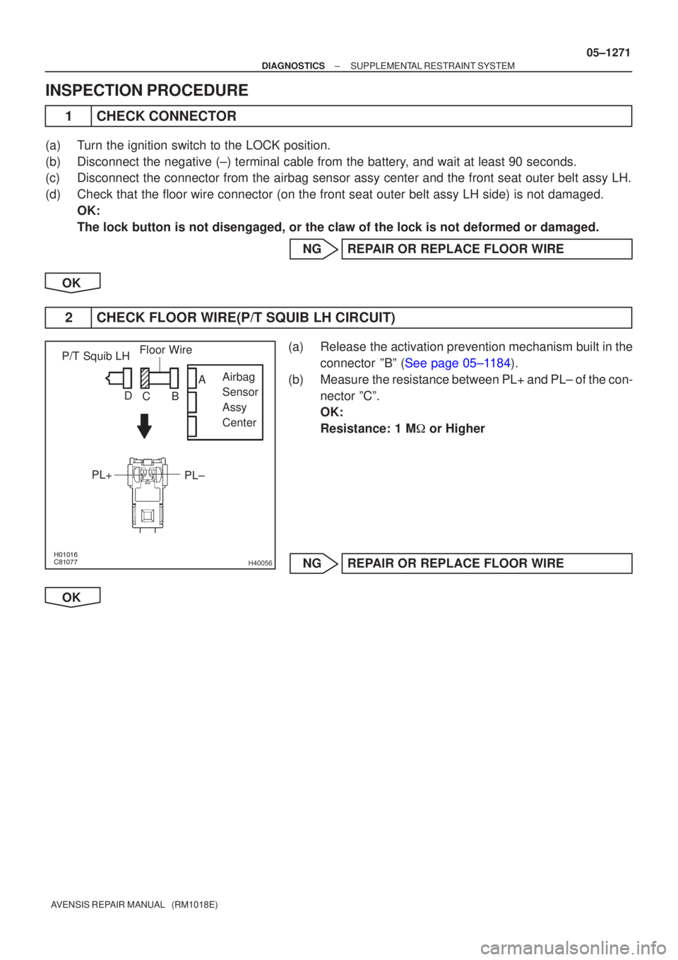
INSPECTION PROCEDURE
1CHECK CONNECTOR
(a)Turn the ignition switch to the LOCK position.
(b)Disconnect the negative (±) terminal cable from the battery, and wait at least 90 seconds.
(c)Disconnect the connector from the airbag sensor assy center and the fron\
t seat outer belt assy LH.
(d)Check that the floor wire connector (on the front seat outer belt assy \
LH side) is not damaged.
OK:
The lock button is not disengaged, or the claw of the lock is not deform\
ed or damaged.
NGREPAIR OR REPLACE FLOOR WIRE
OK
2CHECK FLOOR WIRE(P/T SQUIB LH CIRCUIT)
(a)Release the activation prevention mechanism built in the connector ºBº (See page 05±1184).
(b) Measure the resistance between PL+ and PL± of the con- nector ºCº.
OK:
Resistance: 1 M � or Higher
NG REPAIR OR REPLACE FLOOR WIRE
OK
Page 1294 of 5135

DTC B0133/62 SHORT")
������������H40048
P/T Squib RHPR±
PR+ Airbag
Sensor
Assy
Center
Floor Wire No.2
A
B
C
D
±
DIAGNOSTICS SUPPLEMENTAL RESTRAINT SYSTEM
05±1267
AVENSIS REPAIR MANUAL (RM1018E)
DTC B0133/62 SHORT IN P/T SQUIB (RH) CIRCUIT (TO B+)
CIRCUIT DESCRIPTION
The P/T squib RH circuit consists of the airbag sensor assy center and the \
front seat outer belt assy RH (seat
belt pretensioner RH).
This circuit actuates the SRS to deploy when the SRS deployment conditio\
ns are fulfilled.
DTC B0133/62 is recorded when a short to B+ is detected in the P/T squib\
RH circuit.
DTC No.DTC Detecting ConditionTrouble Area
B0133/62
�Short circuit in P/T squib RH wire harness (to B+)
� P/T squib RH malfunction
� Airbag sensor assy center malfunction�Front seat outer belt assy RH (P/T squib RH)
� Airbag sensor assy center
� Floor wire No.2
WIRING DIAGRAM
See page 05±1258.
INSPECTION PROCEDURE
1 CHECK FLOOR WIRE NO.2(P/T SQUIB RH CIRCUIT)
(a) Turn the ignition switch to the LOCK position.
(b) Disconnect the negative (±) terminal cable from the bat-
tery, and wait for at least 90 seconds.
(c) Disconnect the connectors from the airbag sensor assy center and the front seat outer belt assy RH.
(d) Connect the negative (±) terminal cable to the battery, and turn the ignition switch to the ON position.
(e) Measure the voltage between the body ground and PR+ of the connector ºCº.
OK:
Voltage: Below 1 V
NG REPAIR OR REPLACE FLOOR WIRE NO.2
OK
054M2±07
Page 1297 of 5135

DTC B0132/61 SHORT")
������������H40048
P/T Squib RHPR±
PR+ Airbag
Sensor
Assy
Center
Floor Wire No.2
A
B
C
D
05±1264
±
DIAGNOSTICS SUPPLEMENTAL RESTRAINT SYSTEM
AVENSIS REPAIR MANUAL (RM1018E)
DTC B0132/61 SHORT IN P/T SQUIB (RH) CIRCUIT (TO GROUND)
CIRCUIT DESCRIPTION
The P/T squib RH circuit consists of the airbag sensor assy center and the \
front seat outer belt assy RH (seat
belt pretensioner RH).
This circuit actuates the SRS to deploy when the SRS deployment conditio\
ns are fulfilled.
DTC B0132/61 is recorded when a short to ground is detected in the P/T s\
quib RH circuit.
DTC No.DTC Detecting ConditionTrouble Area
B0132/61
�Short circuit in P/T squib RH wire harness (to ground)
� P/T squib RH malfunction
� Airbag sensor assy center malfunction�Front seat outer belt assy RH (P/T squib RH)
� Airbag sensor assy center
� Floor wire No.2
WIRING DIAGRAM
See page 05±1258.
INSPECTION PROCEDURE
1 CHECK FLOOR WIRE NO.2(P/T SQUIB RH CIRCUIT)
(a) Turn the ignition switch to the LOCK position.
(b) Disconnect the negative (±) terminal cable from the bat-
tery, and wait for at least 90 seconds.
(c) Disconnect the connectors from the airbag sensor assy center and the front seat outer belt assy RH.
(d) Measure the resistance between the body ground and
PR+ of the connector ºCº.
OK:
Resistance: 1 M � or Higher
NG REPAIR OR REPLACE FLOOR WIRE NO.2
OK
054M1±07
Page 1300 of 5135

DTC B0131/64 OPEN IN P")
������������H40048
P/T Squib RHAirbag
Sensor
Assy
Center
PR±
PR+
Floor Wire No.2
A
B
C
D
±
DIAGNOSTICS SUPPLEMENTAL RESTRAINT SYSTEM
05±1261
AVENSIS REPAIR MANUAL (RM1018E)
DTC B0131/64 OPEN IN P/T (RH) CIRCUIT
CIRCUIT DESCRIPTION
The P/T squib RH circuit consists of the airbag sensor assy center and the \
front seat outer belt assy RH (seat
belt pretensioner RH).
This circuit actuates the SRS to deploy when the SRS deployment conditio\
ns are fulfilled.
DTC B0131/64 is recorded when an open circuit is detected in the P/T squ\
ib RH circuit.
DTC No.DTC Detecting ConditionTrouble Area
B0131/64
�Open circuit in PR+ wire harness or PR± wire harness of P/T
squib RH
� P/T squib RH malfunction
� Airbag sensor assy center malfunction�Front seat outer belt assy RH (P/T squib RH)
� Airbag sensor assy center
� Floor wire No.2
WIRING DIAGRAM
See page 05±1258.
INSPECTION PROCEDURE
1 CHECK FLOOR WIRE NO.2(P/T SQUIB RH CIRCUIT)
(a) Turn the ignition switch to the LOCK position.
(b) Disconnect the negative (±) terminal cable from the bat-
tery, and wait for at least 90 seconds.
(c) Disconnect the connectors from the airbag sensor assy center and the front seat outer belt assy RH.
(d) Measure the resistance between PR+ and PR± of the connector ºCº.
OK:
Resistance: Below 1 �
NG REPAIR OR REPLACE FLOOR WIRE NO.2
OK
056M8±03
Page 1303 of 5135
H01454
A28
PR+
PR± Y±B
Y 1
2Airbag Sensor Assy Center
P17
P/T Squib RH
A289
10 05±1258
± DIAGNOSTICSSUPPLEMENTAL RESTRAINT SYSTEM
AVENSIS REPAIR MANUAL (RM1018E)
DTC B0130/63 SHORT IN P/T SQUIB (RH) CIRCUIT
CIRCUIT DESCRIPTION
The P/T squib RH circuit consists of the airbag sensor assy center and the front seat outer belt assy RH (seat
belt pretensioner RH).
This circuit actuates the SRS to deploy when the SRS deployment conditions are fulfilled.
DTC B0130/63 is recorded when a short circuit is detected in the P/T squib RH circuit.
DTC No.DTC Detecting ConditionTrouble Area
B0130/63
�Short circuit between PR+ wire harness and PR± wire har-
ness of P/T squib RH
�P/T squib RH malfunction
�Airbag sensor assy center malfunction�Front seat outer belt assy RH (P/T squib RH)
�Airbag sensor assy center
�Floor wire No.2
WIRING DIAGRAM
056M7±03
Page 1304 of 5135
������������H40048
Airbag
Sensor
Assy
Center
P/T Squib RH
PR±
PR+
Floor Wire No.2
A
B
C
D
±
DIAGNOSTICS SUPPLEMENTAL RESTRAINT SYSTEM
05±1259
AVENSIS REPAIR MANUAL (RM1018E)
INSPECTION PROCEDURE
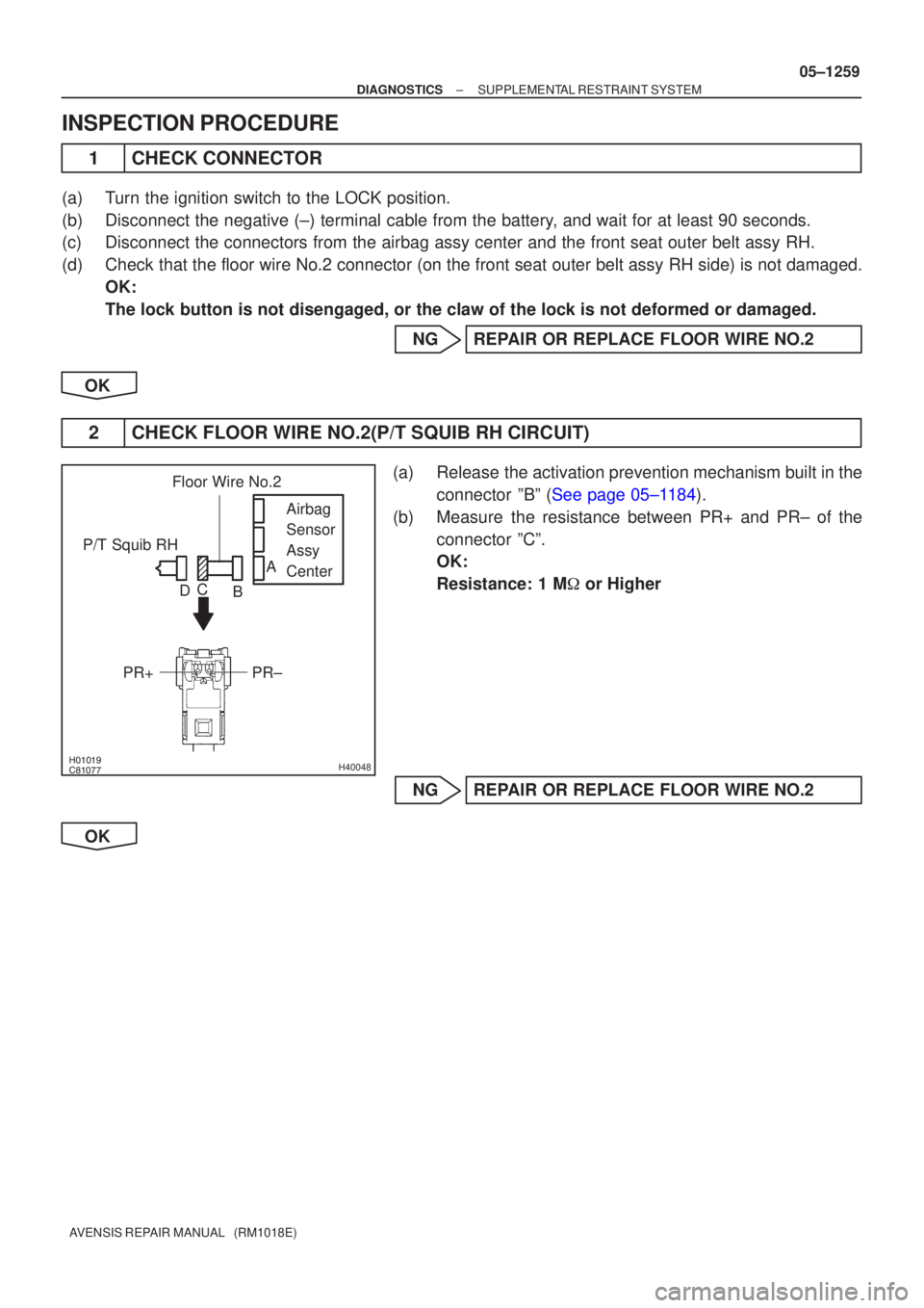
1CHECK CONNECTOR
(a)Turn the ignition switch to the LOCK position.
(b)Disconnect the negative (±) terminal cable from the battery, and wait for at least 90 seconds.
(c)Disconnect the connectors from the airbag assy center and the front seat\
outer belt assy RH.
(d)Check that the floor wire No.2 connector (on the front seat outer belt assy \
RH side) is not damaged.
OK:
The lock button is not disengaged, or the claw of the lock is not deform\
ed or damaged.
NGREPAIR OR REPLACE FLOOR WIRE NO.2
OK
2CHECK FLOOR WIRE NO.2(P/T SQUIB RH CIRCUIT)
(a)Release the activation prevention mechanism built in the connector ºBº (See page 05±1184).
(b) Measure the resistance between PR+ and PR± of the connector ºCº.
OK:
Resistance: 1 M � or Higher
NG REPAIR OR REPLACE FLOOR WIRE NO.2
OK

DTC B0135/73 SHORT IN P/T SQUIB (")

DTC B0130/63 SHORT IN P/T SQUIB")