Page 4329 of 5135

054JC−11
ENGINE CONTROL SYSTEM Check Sheet
Customer’s Name
Date Vehicle
Brought in
VIN
Production Date
Licence Plate No.
Odometer Reading
km
miles
Problem Symptoms
Engine does
not Start
Difficult to
Start
Poor Idling
Poor
Driveability
Engine Stall
Others
Engine does not crankNo initial combustionNo complete combustion
Engine cranks slowly
Other
Incorrect first idleIdling rpm is abnormalHigh ( rpm)Low ( rpm)
Rough idling
Other
HesitationBack fireMuffler explosion (after−fire)Surging
Knocking
Other
Soon after startingAfter accelerator pedal depressed
After accelerator pedal released
During A/C operation
Shifting from N to D
Other
Data Problem
Occurred
Problem Frequency
Condition When
Problem Occurs
Weather
Engine Operation
Engine Temp. Place Outdoor
TemperatureConstant
Sometimes ( times per day/month)Once only
Other
Fine
CloudyRainySnowyVarious/Other
Hot
Warm Cool
HighwaySuburbsInner CityUphillDownhill
Rough road
Other
Cold
Warming upAfter Warming upAny temp.Other
Starting
Just after starting ( min.)IdlingRacing
Driving
Constant speedAccelerationDeceleration
A/C switch ON/OFF
Other
Condition of malfunction indicator lamp
(CHK ENG)Remains on Sometimes lights up Does not light up
Normal Malfunction code(s) (code )
Freeze frame data ( )
Normal Malfunction code(s) (code )
Freeze frame data ( )
Normal mode
(Pre−check)
Check Mode DTC InspectionInspector’s
Name
Cold (approx._C/_F)
− DIAGNOSTICSECD SYSTEM (1CD−FTV)(From September, 2003)
05−269
AVENSIS Supplement (RM1045E)
CUSTOMER PROBLEM ANALYSIS CHECK
Page 4331 of 5135
−
DIAGNOSTICS ECD SYSTEM (1CD −FTV)(From September, 2003)
05 −267
AVENSIS Supplement (RM 1045E)
9 SYMPTOM SIMULATION (See page 05 −282)
1 0 DTC CHECK (See page 05 −290)
AMalfunction code
BNo code
B GO TO STEP 12
A
11 PROCEED TO DTC CHART (See page 05 −299)
GO TO STEP 14
12 BASIC INSPECTION (See page 05 −27 1)
ANot confirm wrong parts
BConfirm wrong parts
B GO TO STEP 17
A
1 3 PROCEED TO PROBLEM SYMPTOMS TABLE (See page 05 −282)
AConfirm wrong circuit
BConfirm wrong Parts
B GO TO STEP 17
A
1 4 CHECK ECM POWER SOURCE CIRCUIT (See page 05 −489)
1 5 CIRCUIT INSPECTION
ANot confirm malfunction
BConfirm malfunction
B GO TO STEP 18
A
Page 4336 of 5135

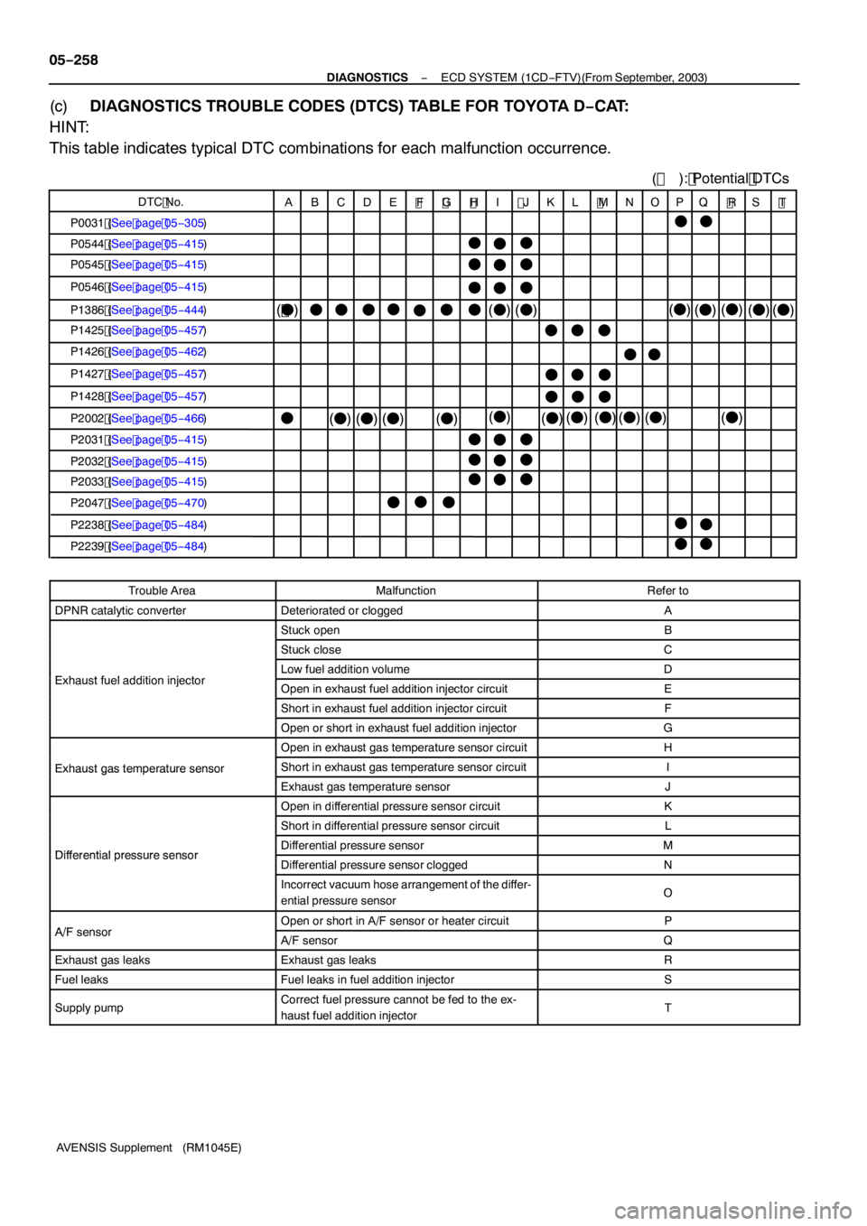
DTC No.
( ): Potential DTCs
( F )
ABCDE F G HI JKL MNOPQ RS T
P003 1 (See page 05 −305)
P0544 (See page 05 −415)
P0545 (See page 05 −415)
P0546 (See page 05 −415)
P 1386 (See page 05 −444)
P 1425 (See page 05 −457)
P 1426 (See page 05 −462)
P 1427 (See page 05 −457)
P 1428 (See page 05 −457)
P2002 (See page 05 −466)
P203 1 (See page 05 −415)
P2032 (See page 05 −415)
P2033 (See page 05 −415)
P2047 (See page 05 −470)
P2238 (See page 05 −484)
P2239 (See page 05 −484)
F
F
F F
F
F FF
FF F F FFF
FF
F
F
F
F FF
F
F
F
F F F
F
F
F
FFF
F (
F )(F)
( F )
(F )(F )(F ) (
F )(F )
( F )
F
F
F F
F
F
(F )(
F )
( F )
( F )(
F )
F F F
F
( F )
( F )(F)( F)
05
−258
−
DIAGNOSTICS ECD SYSTEM (1CD −FTV)(From September, 2003)
AVENSIS Supplement (RM 1045E)
(c) DIAGNOSTICS TROUBLE CODES (DTCS) TABLE FOR TOYOTA D −CAT:
HINT:
This table indicates typical DTC combinations for each malfunction occurrence.
Trouble AreaMalfunctionRefer to
DPNR catalytic converterDeteriorated or cloggedA
Stuck openB
Stuck closeC
Eha stfeladditioi jectoLow fuel addition volumeDExhaust fuel addition injectorOpen in exhaust fuel addition injector circuitE
Short in exhaust fuel addition injector circuitF
Open or short in exhaust fuel addition injectorG
Open in exhaust gas temperature sensor circuitH
Exhaust gas temperature sensorShort in exhaust gas temperature sensor circuitIExhaustgastemperaturesensor
Exhaust gas temperature sensorJ
Open in differential pressure sensor circuitK
Short in differential pressure sensor circuitL
DifferentialpressuresensorDifferential pressure sensorMDifferential pressure sensorDifferential pressure sensor cloggedN
Incorrect vacuum hose arrangement of the differ-
ential pressure sensorO
A/Fse soOpen or short in A/F sensor or heater circuitPA/F sensorA/F sensorQ
Exhaust gas leaksExhaust gas leaksR
Fuel leaksFuel leaks in fuel addition injectorS
Supply pumpCorrect fuel pressure cannot be fed to the ex-
haust fuel addition injectorT
Page 4337 of 5135

− DIAGNOSTICSECD SYSTEM (1CD−FTV)(From September, 2003)
05−259
AVENSIS Supplement (RM1045E)
(d)DIAGNOSTICS TROUBLE CODE DESCRIPTION FOR TOYOTA D−CAT:
DTC No.Description
P0031Open or short in A/F sensor or heater circuit (Low output)
P0544Open or short in exhaust gas temperature sensor circuit (Up stream)
P0545Open or short in exhaust gas temperature sensor circuit (Up stream) (Low output)
P0546Open or short in exhaust gas temperature sensor circuit (Up stream) (High output)
P1386TOYOTA D−CAT fuel addition system malfunction
P1425Open or short in differential pressure sensor circuit
P1426Differential pressure sensor is clogged or has incorrect vacuum hose arrangement
P1427Open or short in differential pressure sensor circuit (Low output)
P1428Open or short in differential pressure sensor circuit (High output)
P2002DPNR Catalytic converter malfunction
P2031Open or short in exhaust gas temperature sensor circuit (Down stream)
P2032Open or short in exhaust gas temperature sensor circuit (Down stream) (Low output)
P2033Open or short in exhaust gas temperature sensor circuit (Down stream) (High output)
P2047Open in exhaust fuel addition injector circuit
P2238Open or short in A/F sensor or heater circuit (Low output)
P2239Open or short in A/F sensor or heater circuit (High output)
Page 4339 of 5135

P0087 (See page 05−314)
P0088 (See page 05 −32 1)
P0093 (See page 05 −328)
P0 190 (See page 05 −314)
P0 192 (See page 05 −314)
P0 193 (See page 05 −314)
P0200 (See page 05 −368)
P0627 (See page 05 −429)
P 1229 (See page 05 −32 1)
P 127 1 (See page 05 −435)
P 1272 (See page 05 −435)
P
1238 (See page 05 −43 1)
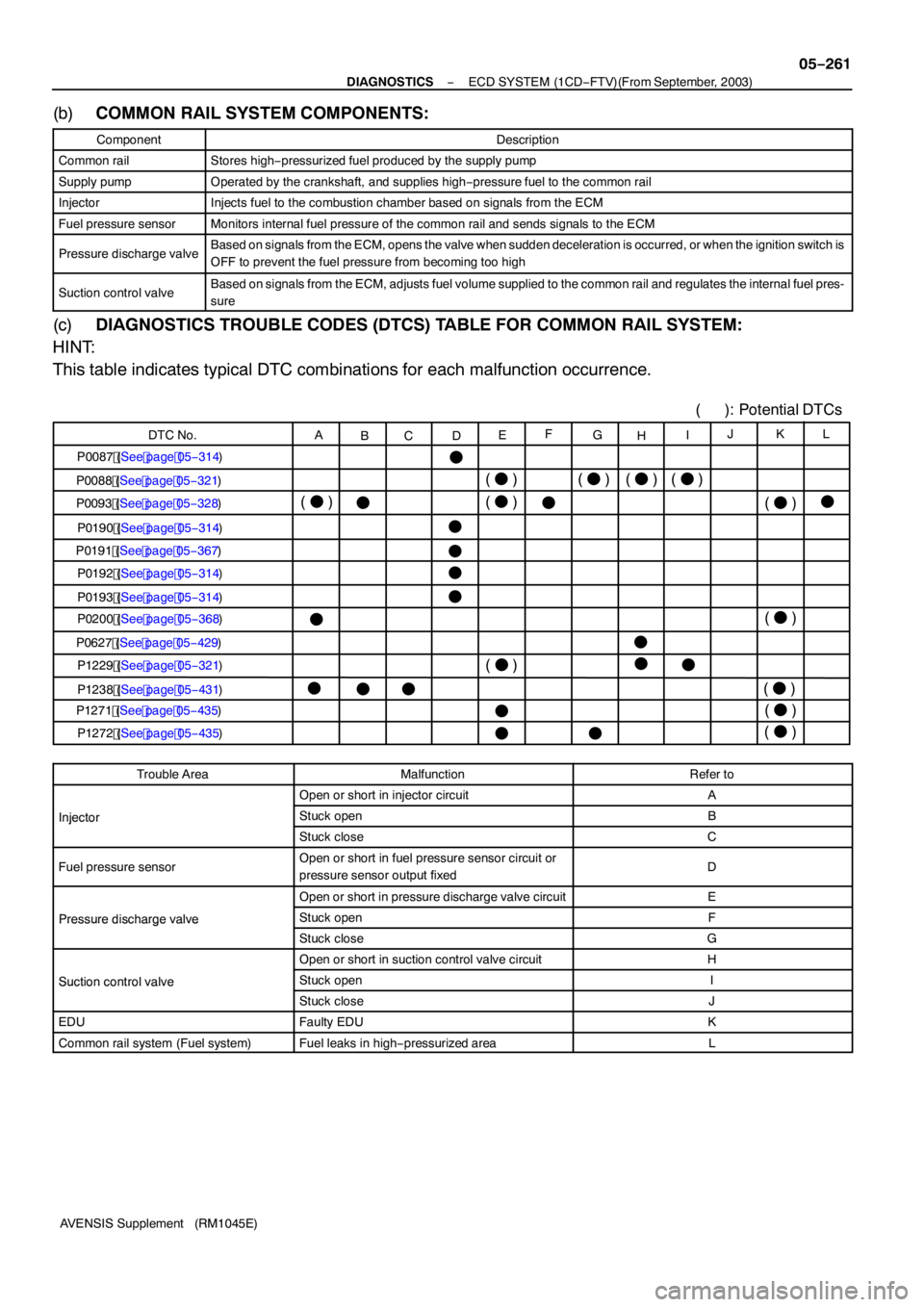
DTC No. A
BC DEF
GH IJKL
(
F )
F
( F )
F F
FF F
F
F
F
F F
(
F )
( F ) F
(
F )( F)( F)
F F
F F (
F )
( F )
( F )
(
F ) F
P0
191 (See page 05 −367)
F ( ): Potential DTCs
(F )
−
DIAGNOSTICS ECD SYSTEM (1CD −FTV)(From September, 2003)
05 −26 1
AVENSIS Supplement (RM 1045E)
(b) COMMON RAIL SYSTEM COMPONENTS:
ComponentDescription
Common railStores high −pressurized fuel produced by the supply pump
Supply pumpOperated by the crankshaft, and supplies high −pressure fuel to the common rail
InjectorInjects fuel to the combustion chamber based on signals from the ECM
Fuel pressure sensorMonitors internal fuel pressure of the common rail and sends signals to the ECM
Pressure discharge valveBased on signals from the ECM, opens the valve when sudden deceleration is occurred, or when the ignition switch is
OFF to prevent the fuel pressure from becoming too high
Suction control valveBased on signals from the ECM, adjusts fuel volume supplied to the common rail and regulates the internal fuel pres-
sure
(c) DIAGNOSTICS TROUBLE CODES (DTCS) TABLE FOR COMMON RAIL SYSTEM:
HINT:
This table indicates typical DTC combinations for each malfunction occurrence.
Trouble AreaMalfunctionRefer to
Open or short in injector circuitA
InjectorStuck openBInjector
Stuck closeC
Fuel pressure sensorOpen or short in fuel pressure sensor circuit or
pressure sensor output fixedD
Open or short in pressure discharge valve circuitE
Pressure discharge valveStuck openFPressuredischargevalve
Stuck closeG
Open or short in suction control valve circuitH
Suction control valveStuck openISuctioncontrolvalve
Stuck closeJ
EDUFaulty EDUK
Common rail system (Fuel system)Fuel leaks in high −pressurized areaL
Page 4340 of 5135
05−262
− DIAGNOSTICSECD SYSTEM (1CD−FTV)(From September, 2003)
AVENSIS Supplement (RM1045E)
(d)DIAGNOSTICS TROUBLE CODE DESCRIPTION FOR COMMON RAIL SYSTEM:
DTC No.Description
P0087Fuel pressure sensor output status at fixed value
P0088Internal fuel pressure too high (200 MPa [2,039 kgf/cm2, 29,007 psi] or more)
P0093Fuel leaks in high−pressurized area
P0190Open or short in fuel pressure sensor circuit (Low or high output)
P0191Fuel pressure sensor output out of range (Low output)
P0192Open or short in fuel pressure sensor circuit (High output)
P0193Open or short in fuel pressure sensor circuit (Sensor1and/or 2 relation)
P0200Open or short in EDU or injector circuit
P0627Open or short in suction control valve circuit
P1229Fuel over−feed
P1238Injection malfunction, exclude open or short in injector circuit
P1271Open or short in pressure discharge valve circuit
P1272Closed malfunction of the pressure discharge valve
Page 4348 of 5135
056II−05
//
How Often Does
Problem Occur?//
Automatic Transaxle
System Check SheetInspector’s
Name :
Customer’s Name
Date Vehicle
Brought In//km
mile
Date Problem
Occurred
ContinuousIntermittent ( times a day)
SymptomsNo up−shift (1st�2nd 2nd�3rd 3rd�4th 4th�5th)
Vehicle does not move ( Any position particular position)
No down−shift ( 5th�4th 4th�3rd 3rd�2nd 2nd�1st)
Lock−up malfunction
Shift point too high or too low
Harsh engagement ( N�D Lock−up Any drive position)
Slip or shudder
No kick−down
Others
DTC Check1st Time
2nd Time Check Item
Normal codeMalfunction code (DTC )
Normal codeMalfunction code (DTC )
Malfunction
Indicator LampNormal
Remains ON
VIN
Odometer Reading Production Date
Licence plate No.
− DIAGNOSTICSELECTRONIC CONTROLLED AUTOMATIC
TRANSAXLE [ECT] (U151E)05−533
AVENSIS Supplement (RM1045E)
CUSTOMER PROBLEM ANALYSIS CHECK
Page 4354 of 5135

05−512
−
DIAGNOSTICS ECD SYSTEM (1CD −FTV)(From September, 2003)
AVENSIS Supplement (RM 1045E)
BLACK SMOKE
HINT:
Specified values in the following troubleshooting flowchart are the reference information.
Because of resultant values in DATA LIST vary depending on measuring conditions, or vehicle’s model
years. Do not judge the vehicle normal even if the DATA LIST values indicate a standard level. There is a
possibility that factors of the malfunction are hiding.
INSPECTION PROCEDURE
1 READ OUTPUT DTCS(RELATED TO ENGINE)
(a) Connect the hand −held tester to the DLC3.
(b) Turn the ignition switch to ON and turn the hand −held tester ON.
(c) Select the item ”DIAGNOSIS / OBD/MOBD / DTC INFO / CURRENT CODES”.
(d) Read DTCs. Result:
Display (DTC Output)Proceed to
Other than engine −related DTCs (See page 05 −266)A
DTCs related to the engine (See page 05 −299)B
B REPAIR OR REPLACE ENGINE CONTROL
SYSTEM ACCORDING TO DTC OUTPUT
(See page 05 −299)
A
2 READ VALUE OF HAND −HELD TESTER
(a) Connect the hand −held tester to the DLC3.
(b) Start the engine and push the hand −held tester ON.
(c) Select the item ”DIAGNOSIS / OBD/MOBD / DATA LIST / ALL / INJ VOLUME and INJ VOL FB # 1to
#4” and read its value displayed on the hand −held tester.
Standard:
ItemEngine Speed *Reference Value
INJ VOLUMEIdling (No engine load)3to 10mm3
INJ VOL FB # 1Idling (No engine load)−4.9 to 4.9 mm3
INJ VOL FB #2Idling (No engine load)−4.9 to 4.9 mm3
INJ VOL FB #3Idling (No engine load)−4.9 to 4.9 mm3
INJ VOL FB #4Idling (No engine load)−4.9 to 4.9 mm3
*: If no conditions are specifically stated for ”ldling”, it means the A/C switch is OFF and all accessory switches
are OFF.
NG Go to step11
OK
05I7Y −01