Page 586 of 5135
B16200
A54393
Wire Harness Side
Ignition Coil with Igniter
Connector
+B
I1I2
I3I4
������A79064IG2 Relay
Engine Room
R/B No. 4 05±444
± DIAGNOSTICSSFI SYSTEM (1AZ±FSE)
AVENSIS REPAIR MANUAL (RM1018E)
Standard (Check for short):
Symbols (Terminal No.)Specified condition
Ignition coil (I1±3) or IGT1 (E13±8) ± Body ground
Ignition coil (I2±3) or IGT2 (E13±9) ± Body groundNo continuityIgnition coil (I3±3) or IGT3 (E13±10) ± Body groundNo continuity
Ignition coil (I4±3) or IGT4 (E13±11) ± Body ground
NG REPAIR OR REPLACE HARNESS OR
CONNECTOR
OK
REPLACE IGNITION COIL ASSY
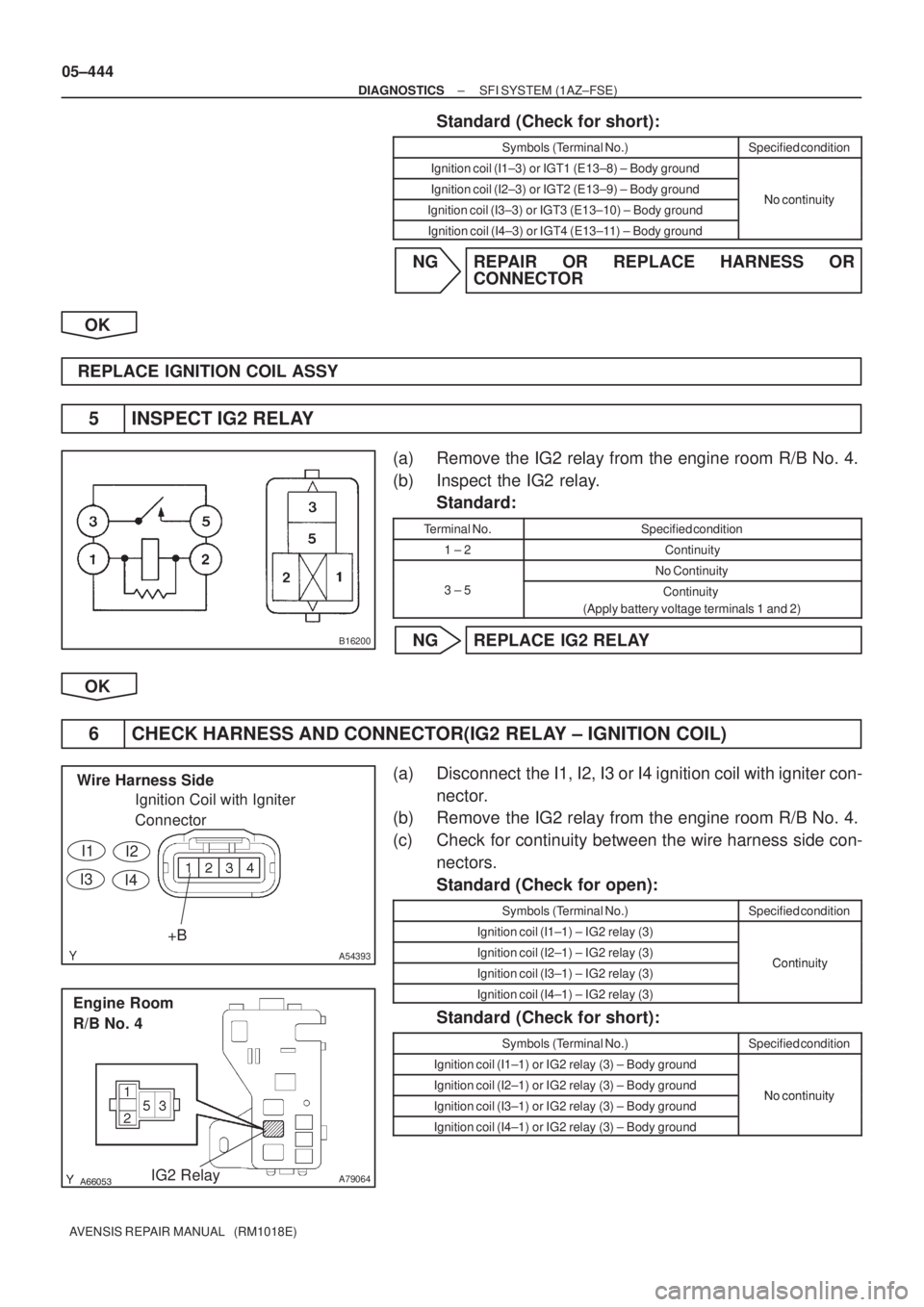
5 INSPECT IG2 RELAY
(a) Remove the IG2 relay from the engine room R/B No. 4.
(b) Inspect the IG2 relay.
Standard:
Terminal No.Specified condition
1 ± 2Continuity
No Continuity
3 ± 5Continuity
(Apply battery voltage terminals 1 and 2)
NG REPLACE IG2 RELAY
OK
6 CHECK HARNESS AND CONNECTOR(IG2 RELAY ± IGNITION COIL)
(a) Disconnect the I1, I2, I3 or I4 ignition coil with igniter con-
nector.
(b) Remove the IG2 relay from the engine room R/B No. 4.
(c) Check for continuity between the wire harness side con-
nectors.
Standard (Check for open):
Symbols (Terminal No.)Specified condition
Ignition coil (I1±1) ± IG2 relay (3)
Ignition coil (I2±1) ± IG2 relay (3)ContinuityIgnition coil (I3±1) ± IG2 relay (3)Continuity
Ignition coil (I4±1) ± IG2 relay (3)
Standard (Check for short):
Symbols (Terminal No.)Specified condition
Ignition coil (I1±1) or IG2 relay (3) ± Body ground
Ignition coil (I2±1) or IG2 relay (3) ± Body groundNo continuityIgnition coil (I3±1) or IG2 relay (3) ± Body groundNo continuity
Ignition coil (I4±1) or IG2 relay (3) ± Body ground
Page 587 of 5135
±
DIAGNOSTICS SFI SYSTEM(1AZ±FSE)
05±445
AVENSIS REPAIR MANUAL (RM1018E)
NGREPAIR OR REPLACE HARNESS OR
CONNECTOR
OK
CHECK FOR FUEL PUMP CONTROL CIRCUIT (See page 05±507)
Page 588 of 5135
A76880
FL MAIN
StarterCircuit
Opening Relay
Park/Neutral
Position SWIG2 Relay
AM2
BatteryECM
STA IGSW IGN Ignition SWFuel Pump
ST2IG2
ST
Relay
(NE Signal) (A/T)FC
IG2STTr
(M/T)
(A/T) AM2
± DIAGNOSTICSSFI SYSTEM (1AZ±FSE)
05±507
AVENSIS REPAIR MANUAL (RM1018E)
FUEL PUMP CONTROL CIRCUIT
CIRCUIT DESCRIPTION
In the diagram below, when the engine is cranked, current flows from terminal ST2 of the ignition switch to
the starter relay coil and also current flows to terminal STA of ECM (STA signal).
When the STA signal and NE signal are input to the ECM, Tr is turned ON, current flows to the coil of the
circuit opening relay, the relay switches on, power is supplied to the fuel pump and the fuel pump operates.
While the NE signal is generated (engine running), the ECM keeps Tr ON (circuit opening relay ON) and the
fuel pump also keeps operating.
05CK1±01
Page 589 of 5135
A76881
IE4B±R
I13
Ignition SW
AM2
FCECM
1
B±R
6 6 4
2
IB1 Engine Room
R/B No. 1
B±G
FL MAIN
BatteryB±R
ECW±B 1ADHE9 10
IC3
32 51
1
3 5
4B 1AM2
IG2
Relay
B±G
F25
Fuel
Pump 4
5
W±B 10 Engine
Room
R/B No. 4IG2
1
24 4
4 4 4A 1C8
Circuit
Opening
Relay 16 DLIGN B±R
(LHD)IP11
(RHD)
IG2
B±R
Driver
Side J/B
B 1
11
2 2
1
Engine Room
R/B No. 4
BR B±WB±WB±WB±W
L±BG±Y G±YG±Y 05±508
± DIAGNOSTICSSFI SYSTEM (1AZ±FSE)
AVENSIS REPAIR MANUAL (RM1018E)
WIRING DIAGRAM
Page 590 of 5135
B16200
A67446
FC (+)
E9E11
E1 (±)
ECM Connector
±
DIAGNOSTICS SFI SYSTEM(1AZ±FSE)
05±509
AVENSIS REPAIR MANUAL (RM1018E)
INSPECTION PROCEDURE
1PERFORM ACTIVE TEST BY HAND±HELD TESTER(OPERATION OF CIRCUIT
OPENING RELAY)
(a)Turn the ignition switch ON.
(b)Select the item ºDIAGNOSIS / OBD/MOBD / ACTIVE TEST / FUEL PUMP/SPDº\
.
(c)Perform the ACTIVE TEST with the engine stopped.
Result: The circuit opening relay operates.
NGGo to step 2
OK
PROCEED TO NEXT CIRCUIT INSPECTION SHOWN ON PROBLEM SYMPTOMS TABLE
(See page 05±320)
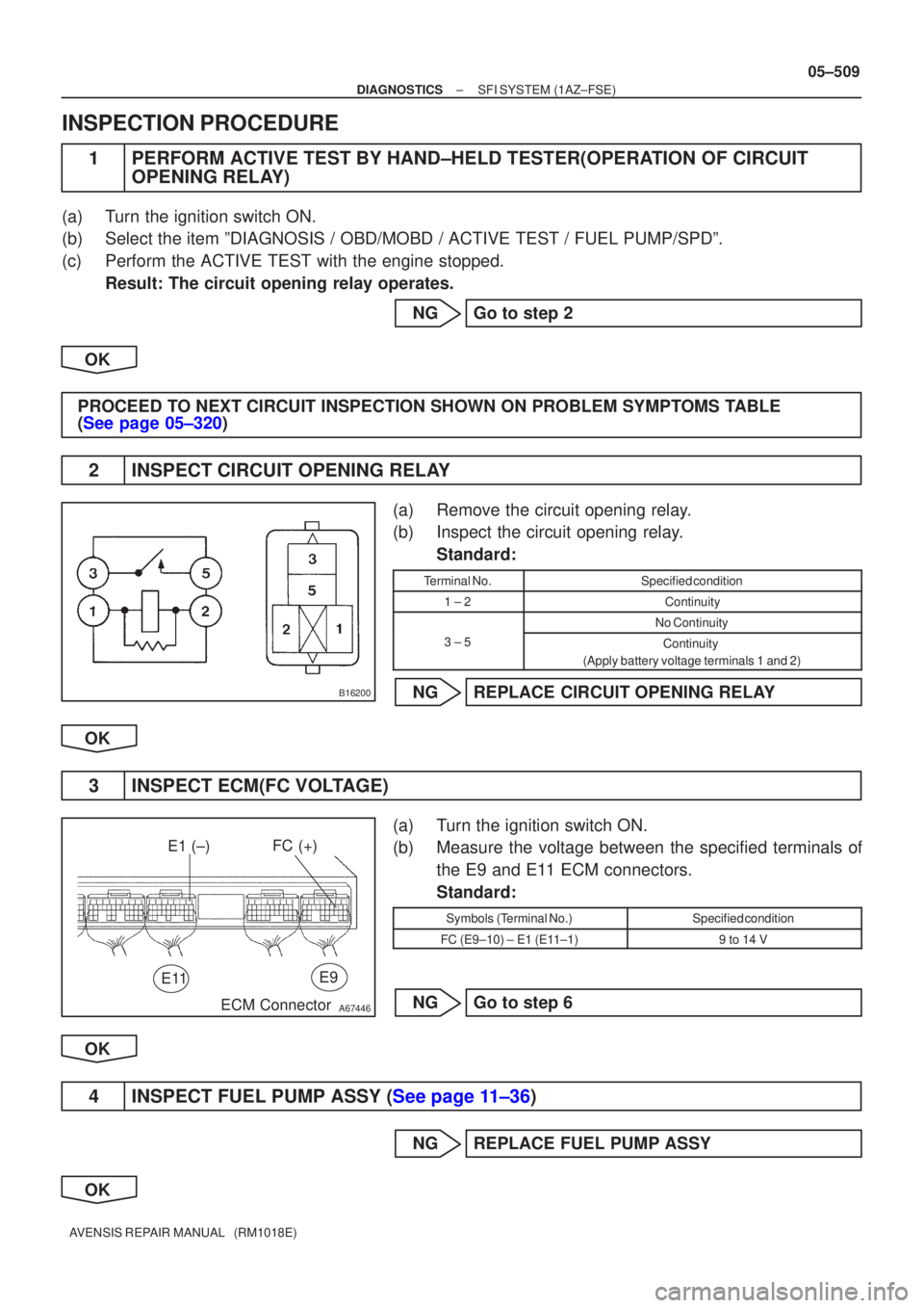
2INSPECT CIRCUIT OPENING RELAY
(a)Remove the circuit opening relay.
(b)Inspect the circuit opening relay. Standard:
Terminal No.Specified condition
1 ± 2Continuity
No Continuity
3 ± 5Continuity
(Apply battery voltage terminals 1 and 2)
NGREPLACE CIRCUIT OPENING RELAY
OK
3INSPECT ECM(FC VOLTAGE)
(a)Turn the ignition switch ON.
(b)Measure the voltage between the specified terminals of the E9 and E11 ECM connectors.
Standard:
Symbols (Terminal No.)Specified condition
FC (E9±10) ± E1 (E11±1)9 to 14 V
NGGo to step 6
OK
4INSPECT FUEL PUMP ASSY (See page 11±36)
NG REPLACE FUEL PUMP ASSY
OK
Page 591 of 5135
123
5
A79099
Wire Harness Side
Circuit Opening Relay Connector
C8
A67586
Wire Harness Side
Fuel Pump Connector
F25
B16200
05±510
±
DIAGNOSTICS SFI SYSTEM(1AZ±FSE)
AVENSIS REPAIR MANUAL (RM1018E)
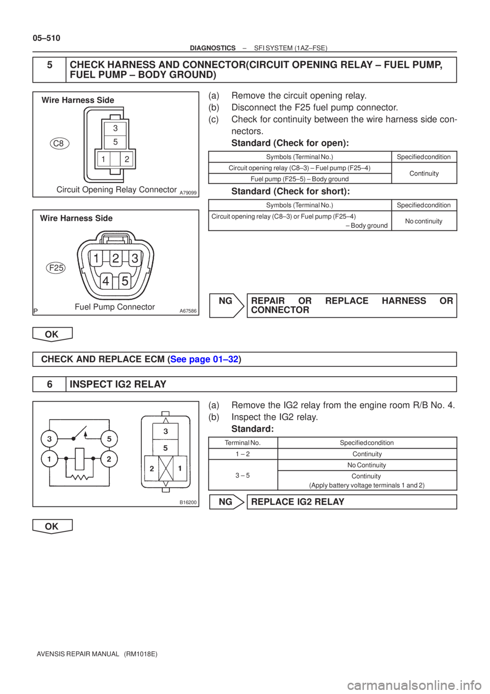
5CHECK HARNESS AND CONNECTOR(CIRCUIT OPENING RELAY ± FUEL PUMP, FUEL PUMP ± BODY GROUND)
(a)Remove the circuit opening relay.
(b)Disconnect the F25 fuel pump connector.
(c)Check for continuity between the wire harness side con-
nectors.
Standard (Check for open):
Symbols (Terminal No.)Specified condition
Circuit opening relay (C8±3) ± Fuel pump (F25±4)ContinuityFuel pump (F25±5) ± Body groundContinuity
Standard (Check for short):
Symbols (Terminal No.)Specified condition
Circuit opening relay (C8±3) or Fuel pump (F25±4)
± Body groundNo continuity
NGREPAIR OR REPLACE HARNESS ORCONNECTOR
OK
CHECK AND REPLACE ECM (See page 01±32)
6 INSPECT IG2 RELAY
(a) Remove the IG2 relay from the engine room R/B No. 4.
(b) Inspect the IG2 relay. Standard:
Terminal No.Specified condition
1 ± 2Continuity
No Continuity
3 ± 5Continuity
(Apply battery voltage terminals 1 and 2)
NG REPLACE IG2 RELAY
OK
Page 592 of 5135
A79096
Driver Side J/B
IGN Fuse
A66267
Ignition Coil Connector
Wire Harness Side
IG2 I13
������A79064IG2 Relay
Engine Room R/B No. 4
������A81706
IG2 Fuse
Engine Room R/B No. 1
2
1
± DIAGNOSTICSSFI SYSTEM (1AZ±FSE)
05±511
AVENSIS REPAIR MANUAL (RM1018E)
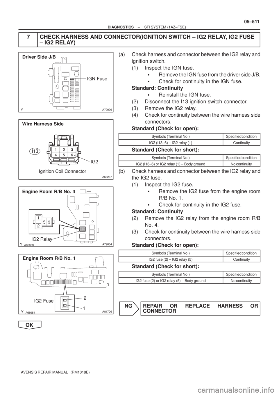
7 CHECK HARNESS AND CONNECTOR(IGNITION SWITCH ± IG2 RELAY, IG2 FUSE
± IG2 RELAY)
(a) Check harness and connector between the IG2 relay and
ignition switch.
(1) Inspect the IGN fuse.
�Remove the IGN fuse from the driver side J/B.
�Check for continuity in the IGN fuse.
Standard: Continuity
�Reinstall the IGN fuse.
(2) Disconnect the I13 ignition switch connector.
(3) Remove the IG2 relay.
(4) Check for continuity between the wire harness side
connectors.
Standard (Check for open):
Symbols (Terminal No.)Specified condition
IG2 (I13±6) ± IG2 relay (1)Continuity
Standard (Check for short):
Symbols (Terminal No.)Specified condition
IG2 (I13±6) or IG2 relay (1) ± Body groundNo continuity
(b) Check harness and connector between the IG2 relay and
the IG2 fuse.
(1) Inspect the IG2 fuse.
�Remove the IG2 fuse from the engine room
R/B No. 1.
�Check for continuity in the IG2 fuse.
Standard: Continuity
(2) Remove the IG2 relay from the engine room R/B
No. 4.
(3) Check for continuity between the wire harness side
connectors.
Standard (Check for open):
Symbols (Terminal No.)Specified condition
IG2 fuse (2) ± IG2 relay (5)Continuity
Standard (Check for short):
Symbols (Terminal No.)Specified condition
IG2 fuse (2) or IG2 relay (5) ± Body groundNo continuity
NG REPAIR OR REPLACE HARNESS OR
CONNECTOR
OK
Page 593 of 5135
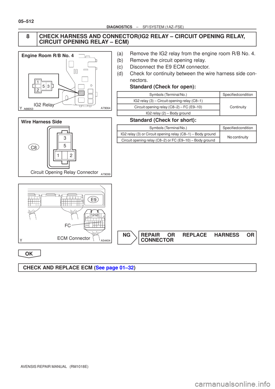
������A79064IG2 Relay
Engine Room R/B No. 4
123
5
A79099Circuit Opening Relay Connector
Wire Harness Side
C8
A54404
FC
ECM Connector E9
05±512
±
DIAGNOSTICS SFI SYSTEM(1AZ±FSE)
AVENSIS REPAIR MANUAL (RM1018E)
8CHECK HARNESS AND CONNECTOR(IG2 RELAY ± CIRCUIT OPENING RELAY, CIRCUIT OPENING RELAY ± ECM)
(a)Remove the IG2 relay from the engine room R/B No. 4.
(b)Remove the circuit opening relay.
(c)Disconnect the E9 ECM connector.
(d)Check for continuity between the wire harness side con-
nectors.
Standard (Check for open):
Symbols (Terminal No.)Specified condition
IG2 relay (3) ± Circuit opening relay (C8±1)
Circuit opening relay (C8±2) ± FC (E9±10)Continuity
IG2 relay (2) ± Body ground
y
Standard (Check for short):
Symbols (Terminal No.)Specified condition
IG2 relay (3) or Circuit opening relay (C8±1) ± Body groundNocontinuityCircuit opening relay (C8±2) or FC (E9±10) ± Body groundNo continuity
NGREPAIR OR REPLACE HARNESS OR CONNECTOR
OK
CHECK AND REPLACE ECM (See page 01±32)