Page 594 of 5135

A76879
IP1I13
Ignition Switch
IGN Driver Side J/B
E9
E11ECM
Battery FL MAINEFI
No. 1
2
B±G2
118
9
18 4DH
2
E9E9
1 12 31 5
EFI
Relay
D
EFBR GR B±W
DA
J/C 1A
J28IGSW
+B2 MREL
E1
Engine Room
J/B No. 41 4A
4BEngine Room
R/B No. 1 and
Engine Room
J/B No. 1 1EFI AM2
1 211
1 2
B±G6
(RHD) IE4 1 (LHD)
B±R B±R B±R
4 4
4
4
4
4Engine Room
R/B No. 4
Engine
Room
R/B No. 4B±Y
B±W
B±R
ECW±B
B±RB±R B±R
(RHD) (LHD)
D J14 D J28 (RHD)(LHD)
D J14
D J28 D J141
E9 +B (RHD)
(LHD)B±W
B±W (RHD)
(LHD)B±W
J26A
J27E
J8
J/CJ/C
CC
IE12
GR
(LHD) (RHD)IP1 IE42
3
AM2 IG2
05±502
± DIAGNOSTICSSFI SYSTEM (1AZ±FSE)
AVENSIS REPAIR MANUAL (RM1018E)
ECM POWER SOURCE CIRCUIT
CIRCUIT DESCRIPTION
When the ignition switch is turned ON, battery positive voltage is applied to terminal IGSW of the ECM and
the EFI relay (Marking: EFI) control circuit in the ECM sends a signal to terminal MREL of the ECM switching
on the EFI relay.
This signal causes current to flow to the coil, closing the contacts of the EFI relay and supplying power to
terminals +B and +B2 of the ECM.
If the ignition switch is turned off, the ECM continues to switch on the EFI relay for maximum 2 seconds for
the initial setting of the throttle valve.
WIRING DIAGRAM
05CK0±01
Page 595 of 5135
+B (+)
ECM Connecter
E11E9
A81698
E1
E11
ECM Connecter
A67446ECM Connecter
E11E9
E1 (±)IGSW (+)
±
DIAGNOSTICS SFI SYSTEM(1AZ±FSE)
05±503
AVENSIS REPAIR MANUAL (RM1018E)
INSPECTION")
A67446
E1 (±)+B (+)
ECM Connecter
E11E9
A81698
E1
E11
ECM Connecter
A67446ECM Connecter
E11E9
E1 (±)IGSW (+)
±
DIAGNOSTICS SFI SYSTEM(1AZ±FSE)
05±503
AVENSIS REPAIR MANUAL (RM1018E)
INSPECTION PROCEDURE
1INSPECT ECM(+B VOLTAGE)
(a)Turn the ignition switch ON.
(b)Measure the voltage between the specified terminals of
the E9 and E11 ECM connectors.
Standard:
Symbols (Terminal No.)Specified condition
+B (E9±1) ± E1 (E11±1)9 to 14 V
OKPROCEED TO NEXT CIRCUIT INSPECTION SHOWN ON PROBLEM SYMPTOMS TABLE
(See page 05±320)
NG
2 CHECK HARNESS AND CONNECTOR(ECM ± BODY GROUND)
(a) Disconnect the battery negative (±) terminal.
(b) Disconnect the E11 ECM connector.
(c) Check for continuity between the wire harness side con- nector.
Standard (Check for open):
Symbols (Terminal No.)Specified condition
E1 (E11±1) ± Body groundContinuity
NG REPAIR OR REPLACE HARNESS OR CONNECTOR
OK
3 INSPECT ECM(IGSW VOLTAGE)
(a) Turn the ignition switch ON.
(b) Measure the voltage between the specified terminals of the E9 and E11 ECM connectors.
Standard:
Symbols (Terminal No.)Specified condition
IGSW (E9±9) ± E1 (E11±1)9 to 14 V
OK Go to step 6
NG
Page 596 of 5135
MREL (+)
05±504
±
DIAGNOSTICS SFI SYSTEM(1AZ±FSE)
AVENSIS REPAIR MANUAL (RM1018E)
4CHECK F")
A79096
Driver Side J/BIGN Fuse
B50489Ignition Switch
I13
Component Side
A67446ECM Connecter
E11E9
E1 (±)MREL (+)
05±504
±
DIAGNOSTICS SFI SYSTEM(1AZ±FSE)
AVENSIS REPAIR MANUAL (RM1018E)
4CHECK FUSE(IGN FUSE)
(a)Remove the IGN fuse from the driver side J/B.
(b)Check for continuity in the IGN fuse. Standard: Continuity
NGCHECK FOR SHORT IN ALL HARNESSES AND COMPONENTS CONNECTED FUSE
OK
5INSPECT IGNITION OR STARTER SWITCH ASSY
(a)Measure the resistance between the connector terminals shown in the chart below.
SwitchTerminal No.Resistance
LOCKAll Terminals1 M� or more
ACC1±31 � or less
ON1±2, 1±3, 2±3, 5±61 � or less
START4±5, 4±6, 5±6, 1±21 � or less
NGREPLACE IGNITION OR STARTER SWITCH
ASSY
OK
CHECK AND REPAIR HARNESS AND CONNECTOR(BATTERY ± IGNITION SWITCH, IGNITION
SWITCH ± ECM)
6INSPECT ECM(MREL VOLTAGE)
(a)Turn the ignition switch ON.
(b)Measure the voltage between the specified terminals of the E9 and E11 ECM connectors.
Standard:
Symbols (Terminal No.)Specified condition
MREL (E9±8) ± E1 (E11±1)9 to 14 V
NGCHECK AND REPLACE ECM (See page 01±32)
OK
Page 597 of 5135
A66054
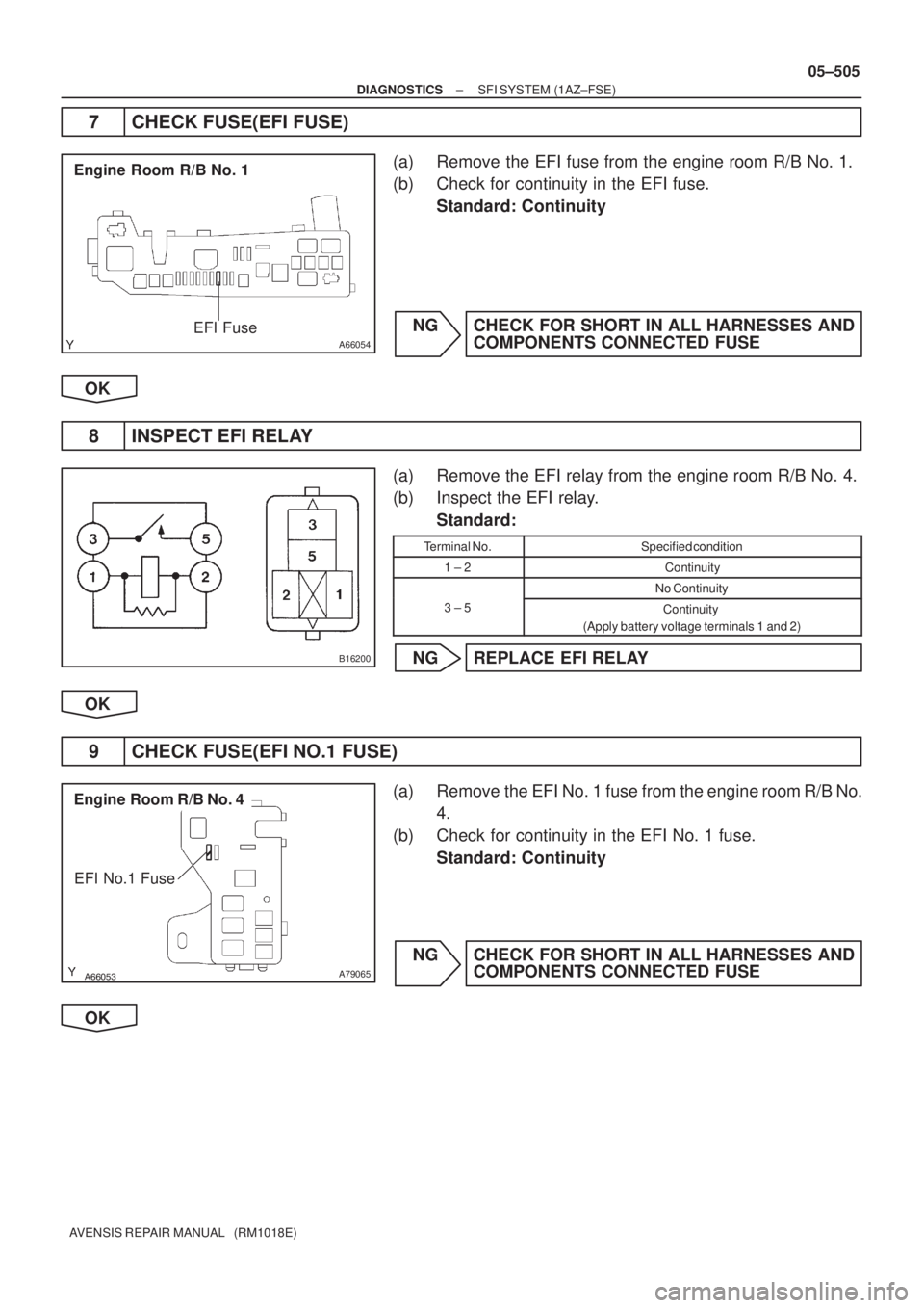
Engine Room R/B No. 1
EFI Fuse
B16200
������
� �
A79065
Engine Room R/B No. 4
EFI No.1 Fuse
± DIAGNOSTICSSFI SYSTEM (1AZ±FSE)
05±505
AVENSIS REPAIR MANUAL (RM1018E)
7 CHECK FUSE(EFI FUSE)
(a) Remove the EFI fuse from the engine room R/B No. 1.
(b) Check for continuity in the EFI fuse.
Standard: Continuity
NG CHECK FOR SHORT IN ALL HARNESSES AND
COMPONENTS CONNECTED FUSE
OK
8 INSPECT EFI RELAY
(a) Remove the EFI relay from the engine room R/B No. 4.
(b) Inspect the EFI relay.
Standard:
Terminal No.Specified condition
1 ± 2Continuity
No Continuity
3 ± 5Continuity
(Apply battery voltage terminals 1 and 2)
NG REPLACE EFI RELAY
OK
9 CHECK FUSE(EFI NO.1 FUSE)
(a) Remove the EFI No. 1 fuse from the engine room R/B No.
4.
(b) Check for continuity in the EFI No. 1 fuse.
Standard: Continuity
NG CHECK FOR SHORT IN ALL HARNESSES AND
COMPONENTS CONNECTED FUSE
OK
Page 598 of 5135

AVENSIS REPA")
A66053
Engine Room R/B No. 4
EFI Relay
������
�
A79066
Engine Room R/B No. 4
EFI No.1 Fuse
1
2
A67445
MREL
E9
ECM Connector+B
Wire Harness Side
05±506
± DIAGNOSTICSSFI SYSTEM (1AZ±FSE)
AVENSIS REPAIR MANUAL (RM1018E)
10 CHECK HARNESS AND CONNECTOR(EFI RELAY ± ECM, EFI RELAY ± BODY
GROUND)
(a) Check harness and connector between the EFI relay and
the ECM connector.
(1) Remove the EFI relay from the engine room R/B No.
4.
(2) Remove the EFI No.1 fuse from the engine room
R/B No. 4.
(3) Disconnect the E9 ECM connector.
(4) Check for continuity between the wire harness side
connectors.
Standard (Check for open):
Symbols (Terminal No.)Specified condition
EFI relay (1) ± MREL (E9±8)
EFI relay (3) ± EFI No. 1 fuse (1)Continuity
EFI No. 1 fuse (2) ± +B (E9±1)
y
Standard (Check for short):
Symbols (Terminal No.)Specified condition
EFI relay (1) or MREL (E9±8) ± Body ground
EFI relay (3) or EFI No. 1 fuse (1) ± Body groundNo continuity
EFI No. 1 fuse (2) or +B (E9±1) ± Body ground
y
(b) Check harness and connector between the EFI relay and
the body ground.
(1) Remove the EFI relay from the engine room R/B No.
4.
(2) Check for continuity between the wire harness side
connector and the body ground.
Standard (Check for open):
Symbols (Terminal No.)Specified condition
EFI relay (2) ± Body groundContinuity
OK REPAIR OR REPLACE HARNESS OR
CONNECTOR
NG
CHECK AND REPAIR HARNESS AND CONNECTOR(TERMINAL +B OF ECM ± BATTERY POSITIVE
TERMINAL)
Page 599 of 5135
05±492
± DIAGNOSTICSSFI SYSTEM (1AZ±FSE)
AVENSIS REPAIR MANUAL (RM1018E)
DTC P2120 THROTTLE/PEDAL POSITION
SENSOR/SWITCH ºDº CIRCUIT
DTC P2122 THROTTLE/PEDAL POSITION
SENSOR/SWITCH ºDº CIRCUIT LOW INPUT
DTC P2123 THROTTLE/PEDAL POSITION
SENSOR/SWITCH ºDº CIRCUIT HIGH INPUT
DTC P2125 THROTTLE/PEDAL POSITION
SENSOR/SWITCH ºEº CIRCUIT
DTC P2127 THROTTLE/PEDAL POSITION
SENSOR/SWITCH ºEº CIRCUIT LOW INPUT
DTC P2128 THROTTLE/PEDAL POSITION
SENSOR/SWITCH ºEº CIRCUIT HIGH INPUT
DTC P2138 THROTTLE/PEDAL POSITION
SENSOR/SWITCH ºDº/ºEº VOLTAGE
CORRELATION
HINT:
This is procedure of accelerator pedal position sensor.
05CKT±01
Page 600 of 5135
125
VPA1 VPA2
5
Movable Range
Usable Range
Usable Range *1
*1
Movable Range
Usable Range
*2
Accelerator pedal released (15�)
Accelerator pedal depressed
(")
A71015
0
Accelerator Pedal Opening Angle (deg)125
VPA1 VPA2
5
Movable Range
Usable Range
Usable Range *1
*1
Movable Range
Usable Range
*2
Accelerator pedal released (15�)
Accelerator pedal depressed
(about 100�)
Accelerator Pedal
Position Sensor
Output Voltage (V)
VPA2VPA1 EP2
VCP2
*1:
*
2:
EP1
0.8
105
VCP1*2
*2*1
± DIAGNOSTICSSFI SYSTEM (1AZ±FSE)
05±493
AVENSIS REPAIR MANUAL (RM1018E)
CIRCUIT DESCRIPTION
HINT:
This electrical throttle system is no used throttle cable.
The accelerator pedal position sensor is mounted on the accelerator pedal bracket and it have the 2 sensors
to detect the accelerator position and a malfunction of the accelerator position sensor.
In the accelerator pedal position sensor, the voltage applied to VPA1 and VPA2 of the ECM changes be-
tween 0 V and 5 V in proportion to the opening angle of the accelerator pedal. The VPA1 is a signal to indicate
the actual accelerator pedal opening angle which is used for the engine control, and the VPA2 is a signal
to indicate the information about VPA1 which is used for detecting a malfunction in VPA1.
The ECM monitors the current opening angle of the accelerator pedal from these signals input from VPA1
and VPA2, and controls the throttle motor based on these signals.
Page 601 of 5135

AVENSIS REPAIR MANUAL (RM1018E)DTC No.
DTC Detection ConditionTrouble Area
P2120
Condition (a) continues for 0.5 sec. or more:
(a) VPA less than 0.2 V and")
05±494
± DIAGNOSTICSSFI SYSTEM (1AZ±FSE)
AVENSIS REPAIR MANUAL (RM1018E)DTC No.
DTC Detection ConditionTrouble Area
P2120
Condition (a) continues for 0.5 sec. or more:
(a) VPA less than 0.2 V and VPA2 greater than 0.97 deg, or
VPA greater than 4.8 V
P2122
Conditions (a) and (b) continue for 0.5 sec. or more:
(a) VPA less than 0.2 V
(b) VPA2 greater than 0.97 deg
P2123Condition (a) continues for 2.0 sec. or more:
(a) VPA greater than 4.8 V
P2125
Condition (a) continues for 0.5 sec. or more:
(a) VPA2 less than 0.5 V and VPA greater than 0.97 deg, or
VPA2 greater than 4.8 V and VPA greater than 0.2 V but
less than 3.45 V
�Open or short in accelerator pedal position sensor circuit
�Accelerator pedal position sensor
�ECM
P2127
Conditions (a) and (b) continue for 0.5 sec. or more:
(a) VPA2 less than 0.5 V
(b) VPA greater than 0.97 deg
P2128
Conditions (a) and (b) continue for 2.0 sec. or more:
(a) VPA2 greater than 4.8 V
(b) VPA greater than 0.2 V but less than 3.45 V
P2138
Condition (a) or (b) continues for 2.0 sec. or more:
(a) Difference between VPA and VPA2 less than 0.02 V
(b) VPA less than 0.2 V and VPA2 less than 0.5 V
HINT:
After confirming ºDTC P2120, P2122, P2123, P2125, P2127, P2128 and P2138º, use the hand±held tester
to confirm the accelerator pedal position sensor output voltage.
Accelerator pedal position expressed as voltage output
Trouble areaAccelerator pedal releasedAccelerator pedal depressed
ACCEL POS #1ACCEL POS #2ACCEL POS #1ACCEL POS #2
VCP circuit open0 V0 V0 V0 V
VPA circuit open or ground short0 V1.5 to 2.9 V0 V3.5 to 5.5 V
VPA2 circuit open or ground short0.5 to 1.1 V0 V2.5 to 4.6 V0 V
EP circuit open5 V5 V5 V5 V

AVENSIS REPAIR MANUAL (RM1018E)
DTC P2120 THROTTLE/PEDAL POSITION
SENSOR/SWITCH ºDº CIRCUIT
DTC P2122 THROTTLE/PEDAL POSITION
SENSOR/SWITCH ºDº CIRCUI")