Page 824 of 5135

BR3893
Malfunction Code (Example Code 72 76)
ON
OFF
0.5 sec. 0.5 sec.1.5 sec.
0.5 sec.2.5 sec.
0.5 sec. 72 7 6
4 sec.
Repeat 05±764
± DIAGNOSTICSABS WITH EBD & BA & TRC & VSC SYSTEM
AVENSIS REPAIR MANUAL (RM1018E)
�If 2 or more DTCs are detected at the same time, the low-
est numbered code is displayed first.
(f) After the check, disconnect the SST from terminal Ts and
CG, Tc and CG of DLC3 and turn the ignition switch to
OFF.
SST 09843±19040
6. With using hand±held tester:
ABS SENSOR SIGNAL CHECK (TEST MODE)
NOTICE:
After replacing the steering angle sensor and/or ECU, perform zero point calibration of the steering
angle sensor or system decision (When replacing the ECU) (See step 7.).
HINT:
If the ignition switch is turned from ON to ACC or LOCK during test mode, the DTCs will be erased.
(a) Hook up the hand±held tester to the DLC3.
(b) Perform step 5. (c) to (d) on the previous page.
(c) Read the DTC by following the prompts on the tester screen.
HINT:
Please refer to the hand±held tester operator's manual for further details.
7. STEERING ANGLE SENSOR ZERO POINT CALIBRATION
NOTICE:
When replacing the steering angle sensor with column assembly or ECU, Engine and ECT ECU (A/T),
Engine ECU (M/T) or when adjusting the front wheel alignment or steering wheel center point in ac-
cordance with the removing or installing or replacing the suspension, axle or steering parts, make
sure to perform steering angle sensor zero point calibration.
(a) Using SST, connect terminals Ts and CG of the DLC3
.
SST 09843±18040
(b) Turn the ignition switch ON and keep the shift lever at P range.
(c) Make sure the steering off center angle is less than �3� when assembling the steering wheels (Smaller
value is desirable).
(d) Press the TRC OFF switch and hold it.
(e) Check that the following conditions are satisfied.
HINT:
�Engine warning light comes on.
�ABS warning light is blinking.
(f) Depress the brake pedal 3 times or more within 2 seconds.
Page 826 of 5135
0542O±04
ABS & EBD & BA Check SheetInspector 's
Name:
Customer 's Name
Date Vehicle
Brought InOdometer Reading/ /
/ /
Date Problem First Occurred
Frequency Problem Occurs/ /
ContinuousIntermittent ( times a day)
ABS does not operate.
ABS does not operate efficiently.
ABS Warning Light
Remains ONDoes not Light Up
DTC Check1st Time
2nd TimeNormal Code
Malfunction Code (Code )
Normal CodeMalfunction Code (Code )
Symptomskm
miles
Brake Warning
Light
(PKB released)Remains ONDoes not Light Up
BA does not operate.
EBD does not operate.
STOP LIGHT SW
SYSTEM
Freeze Frame Data
#IG ON
VEHICLE SPDON
OFF
NO SYS
ABS
BA
FAIL SF
km/h
MPH VIN
Licence No. Production Date 05±754
± DIAGNOSTICSABS WITH EBD & BA & TRC & VSC SYSTEM
AVENSIS REPAIR MANUAL (RM1018E)
CUSTOMER PROBLEM ANALYSIS CHECK
Page 829 of 5135
± DIAGNOSTICSABS WITH EBD & BA & TRC & VSC SYSTEM
05±753
AVENSIS REPAIR MANUAL (RM1018E)
10 Identification of Problem
11 Repair
12 Confirmation Test
End
HINT:
Step 3, 6, 9, 12:
Diagnostic steps permitting the use of the hand±held tester.
Fail safe function:
When a failure occurs in the ABS & BA & TRC & VSC systems, the ABS warning light, the VSC warning light
and the TRC OFF indicator light come on and the ABS & BA & TRC & VSC operations are prohibited. In
addition to this, when the failure that disables the EBD operation occurs, the brake warning light comes on
as well and the EBD operation is prohibited.
Page 834 of 5135
05±744
± DIAGNOSTICSABS WITH EBD SYSTEM
AVENSIS REPAIR MANUAL (RM1018E)
BRAKE WARNING LIGHT CIRCUIT
CIRCUIT DESCRIPTION
The Brake warning light comes on when the brake fluid is insufficient, the parking brake is applied or the EBD
is defective.
0577X±04
Page 836 of 5135

05±746
±
DIAGNOSTICS ABS WITH EBD SYSTEM
AVENSIS REPAIR MANUAL (RM1018E)
INSPECTION PROCEDURE
1RECONFIRM DTC
(a)Check the DTC (See page 05±699). OK:
Normal code
NGREPAIR CIRCUIT INDICATED BY OUTPUTCODE
OK
2INSPECT PARKING BRAKE SWITCH CIRCUIT
(a)Check for an open or short circuit in the parking brake switch circuit (See page 01±32). NGREPAIR OR REPLACE PARKING BRAKESWITCH CIRCUIT
OK
3INSPECT BRAKE FLUID LEVEL WARNING SWITCH CIRCUIT
(a)Check the brake fluid level in reservoir.
(b)Check for an open or shot circuit in brake fluid level warning switch ci\
rcuit (See page 01±32). NG REPAIR OR REPLACE BRAKE FLUID LEVELWARNING SWITCH CIRCUIT
OK
4 INSPECT VACUUM WARNING SWITCH CIRCUIT
(a) Check for an open or short circuit in harness and connector between the vacuum warning switch and skid control ECU (See page 01±32).
NG REPAIR OR REPLACE HARNESS ORCONNECTOR
OK
5 INSPECT COMBINATION METER ASSEMBLY(BRAKE WARNING LIGHT CIRCUIT)
(a)Check for an open or short circuit in the combination meter (See page 01±32). NG REPAIR OR REPLACE COMBINATION METERASSEMBLY
OK
Page 840 of 5135

INSPECTION PROCEDURE
HINT:
Start the inspection from step 1 if you are using the hand±held tester and\
start from step 2")
±
DIAGNOSTICS ABS WITH EBD SYSTEM
05±743
AVENSIS REPAIR MANUAL (RM1018E)
INSPECTION PROCEDURE
HINT:
Start the inspection from step 1 if you are using the hand±held tester and\
start from step 2 if you are not using
the hand±held tester.
1PERFORM ACTIVE TEST BY HAND±HELD TESTER(ABS WARNING LIGHT)
(a)Check that ºONº and ºOFFº of the ABS warning light is shown \
on the combination meter by the
hand±held tester.
OKREPLACE BRAKE ACTUATOR ASSY(See page 32±54)
NG
2INSPECT COMBINATION METER ASSY(ABS WARNING LIGHT) (See page 71±1)
(a)Disconnect the connector from the skid control ECU.
(b)Turn the ignition switch ON.
(c)Check the ABS warning light.
OK:
ABS warning light comes on
NGREPAIR OR REPLACE COMBINATION METERASSY
OK
3CHECK HARNESS AND CONNECTOR(WA CIRCUIT)
(a)Check for a short circuit in harness and connector between terminal WA of the skid control ECU and combination meter (See page 01±32).
NG REPAIR OR REPLACE HARNESS ORCONNECTOR
OK
REPLACE BRAKE ACTUATOR ASSY(See page 32±54)
Page 844 of 5135
F45088GNDGND
F45088GNDGNDWA
05±740
±
DIAGNOSTICS ABS WITH EBD SYSTEM
AVENSIS REPAIR MANUAL (RM1018E)
4INSPECT SKID CONTROL ECU CONNECTOR(GND TERMINAL CONTINUITY)
(a)Measure resistance between terminal GND of the skid control ECU harness side connector and body ground.
Resistance: 1 � or less
NGREPAIR OR REPLACE HARNESS OR CONNECTOR(GND TERMINAL ± BODY
GROUND)(See page 01±32)
OK
CHECK AND REPAIR HARNESS AND CONNECTOR(BATTERY ± IG1 TERMINAL)
(See page 01±32)
5INSPECT COMBINATION METER(ABS WARNING LIGHT)
(a)Disconnect the skid control ECU connector.
(b)Using service wire, connect terminals WA and GND of the skid control ECU harness side connector.
(c)Turn the ignition switch ON. OK:
ABS warning light goes off.
NGREPAIR OR REPLACE COMBINATION METER
OK
REPLACE BRAKE ACTUATOR ASSY(See page 32±54)
Page 851 of 5135
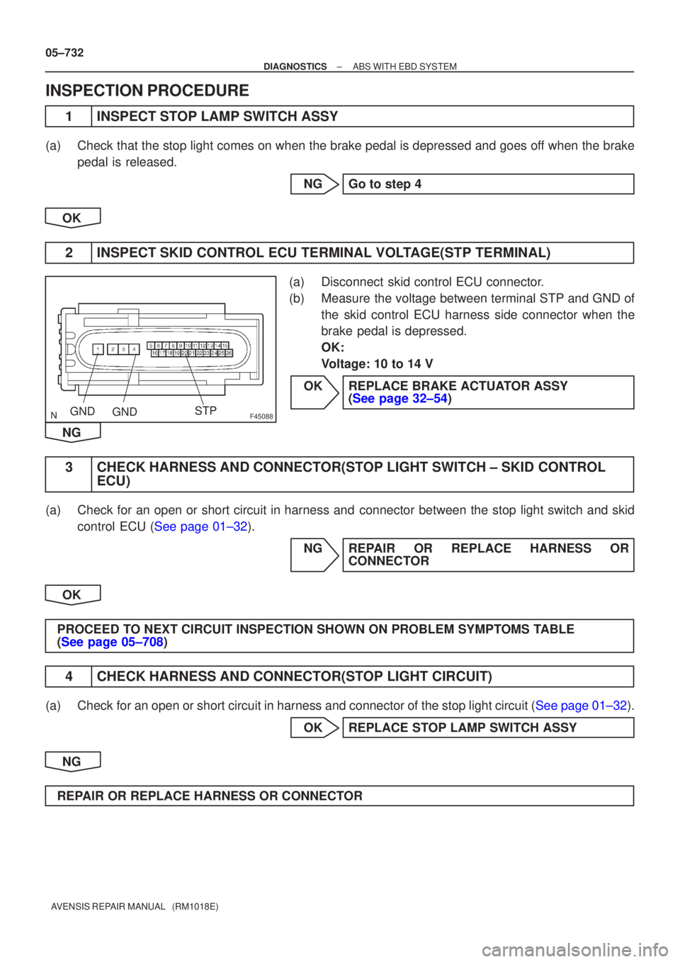
F45088GNDGNDSTP
05±732
±
DIAGNOSTICS ABS WITH EBD SYSTEM
AVENSIS REPAIR MANUAL (RM1018E)
INSPECTION PROCEDURE
1INSPECT STOP LAMP SWITCH ASSY
(a)Check that the stop light comes on when the brake pedal is depressed and goes\
off when the brake pedal is released.
NGGo to step 4
OK
2INSPECT SKID CONTROL ECU TERMINAL VOLTAGE(STP TERMINAL)
(a)Disconnect skid control ECU connector.
(b)Measure the voltage between terminal STP and GND of the skid control ECU harness side connector when the
brake pedal is depressed.
OK:
Voltage: 10 to 14 V
OKREPLACE BRAKE ACTUATOR ASSY (See page 32±54)
NG
3 CHECK HARNESS AND CONNECTOR(STOP LIGHT SWITCH ± SKID CONTROL ECU)
(a) Check for an open or short circuit in harness and connector between the stop light switch and skid
control ECU (See page 01±32).
NG REPAIR OR REPLACE HARNESS ORCONNECTOR
OK
PROCEED TO NEXT CIRCUIT INSPECTION SHOWN ON PROBLEM SYMPTOMS TABLE
(See page 05±708)
4 CHECK HARNESS AND CONNECTOR(STOP LIGHT CIRCUIT)
(a)Check for an open or short circuit in harness and connector of the stop light\
circuit (See page 01±32). OK REPLACE STOP LAMP SWITCH ASSY
NG
REPAIR OR REPLACE HARNESS OR CONNECTOR


