Page 4863 of 5135
D26404
Thrust Needle Roller Bearing
Thrust Bearing Race
D26393
Planetary
Carrier
Thrust
Washer
No.2
Rear
Planetary
Sun Gear
D26598
Thrust Needle
Roller Bearing
1−Way Clutch Assy
D03909
1−Wa y
Clutch
Inner Race
D03589
1−Way Clutch
Sleeve Outer
− AUTOMATIC TRANSMISSION / TRANSAUTOMATIC TRANSAXLE ASSY (U151E/U151F)
40−33
U151E, U151F A/T REPAIR MANUAL (RM1021U)
(b) Remove the thrust needle roller bearing and thrust bear-
ing race from the rear planetary sun gear assy.
(c) Remove the planetary carrier thrust washer No.2 from the
rear planetary sun gear assy.
55. REMOVE1WAY CLUTCH ASSY
(a) Remove the 1−way clutch assy and the thrust needle roll-
er bearing from the transaxle case.
(b) Remove the 1−way clutch inner race from the 1−way
clutch assy.
56. REMOVE1WAY CLUTCH SLEEVE OUTER
(a) Remove the 1−way clutch sleeve outer from the transaxle
case.
Page 4864 of 5135

D26394
Planetary Carrier
Thrust Washer No.1
D26395
Snap Ring
D26717
D08058
Snap Ring
D26396
Second Brake
Piston Assy
40−34
− AUTOMATIC TRANSMISSION / TRANSAUTOMATIC TRANSAXLE ASSY (U151E/U151F)
U151E, U151F A/T REPAIR MANUAL (RM1021U)
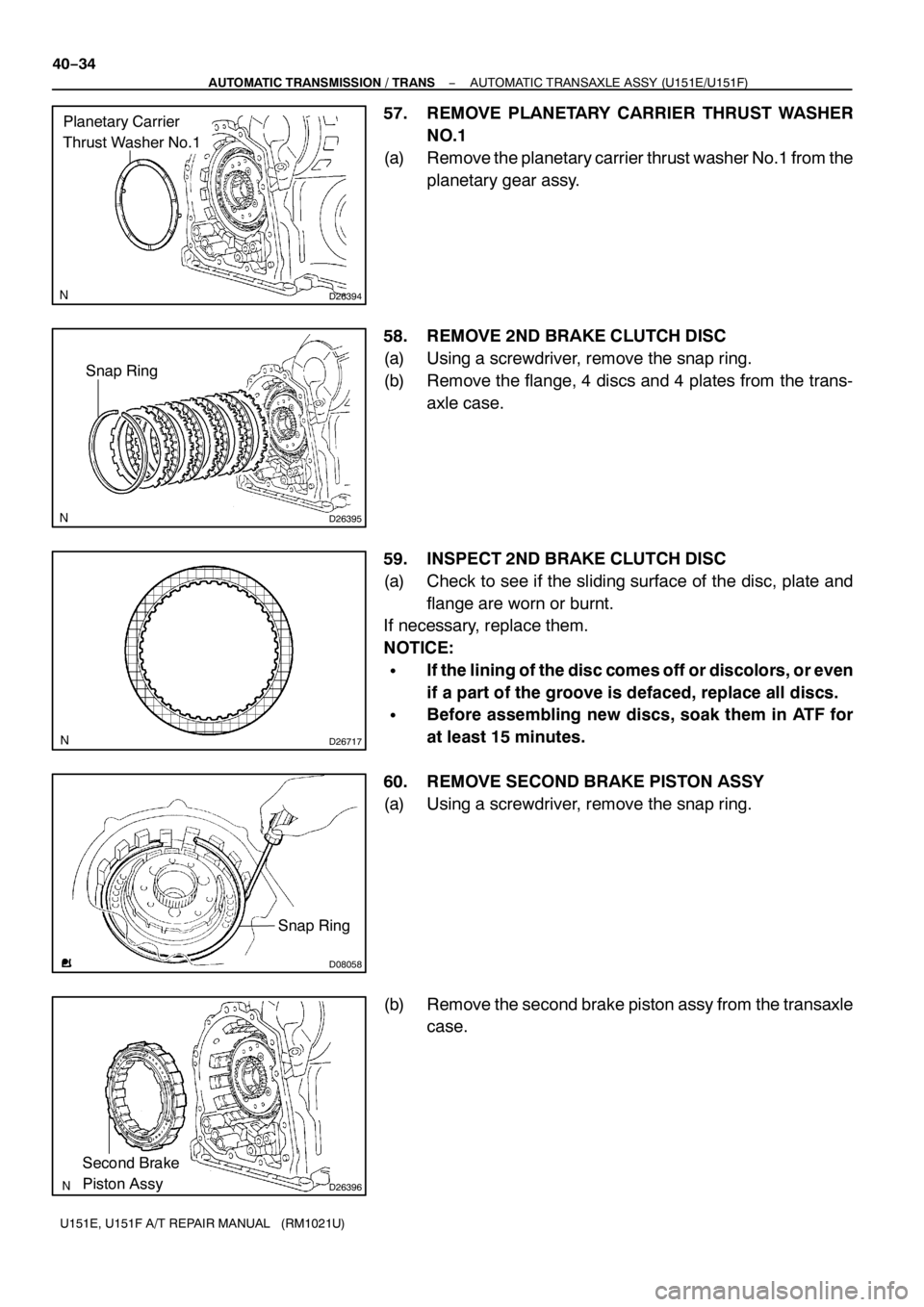
57. REMOVE PLANETARY CARRIER THRUST WASHER
NO.1
(a) Remove the planetary carrier thrust washer No.1 from the
planetary gear assy.
58. REMOVE 2ND BRAKE CLUTCH DISC
(a) Using a screwdriver, remove the snap ring.
(b) Remove the flange, 4 discs and 4 plates from the trans-
axle case.
59. INSPECT 2ND BRAKE CLUTCH DISC
(a) Check to see if the sliding surface of the disc, plate and
flange are worn or burnt.
If necessary, replace them.
NOTICE:
SIf the lining of the disc comes off or discolors, or even
if a part of the groove is defaced, replace all discs.
SBefore assembling new discs, soak them in ATF for
at least15 minutes.
60. REMOVE SECOND BRAKE PISTON ASSY
(a) Using a screwdriver, remove the snap ring.
(b) Remove the second brake piston assy from the transaxle
case.
Page 4865 of 5135

D03616
Snap Ring
D26591
Rear Planetary
Gear Assy
D03873
Thrust Bearing
Race No.2
Thrust Needle Roller BearingInput
Sun
Gear
D26397
D09189
− AUTOMATIC TRANSMISSION / TRANSAUTOMATIC TRANSAXLE ASSY (U151E/U151F)
40−35
U151E, U151F A/T REPAIR MANUAL (RM1021U)
61. REMOVE REAR PLANETARY GEAR ASSY
(a) Using a screwdriver, remove the snap ring.
(b) Remove the rear planetary gear assy from the transaxle
case.
62. REMOVE INPUT SUN GEAR
(a) Remove the 2 thrust needle roller bearings, thrust bearing
race No.2 and input sun gear from the transaxle case.
63. REMOVE1ST & REVERSE BRAKE CLUTCH DISC
(a) Remove the flange, 6 discs and 6 plates from the trans-
axle case.
64. INSPECT1ST & REVERSE BRAKE CLUTCH DISC
(a) Check to see if the sliding surface of the disc, plate and
flange are worn or burnt.
If necessary, replace them.
NOTICE:
SIf the lining of the disc comes off or discolors, or even
if a part of the groove is defaced, replace all discs.
SBefore assembling new discs, soak them in ATF for
at least15 minutes.
Page 4870 of 5135
D03605
SSTHold
Turn
D03914
Underdrive
Clutch Drum
Oil Seal Ring
D26383
D03606
SST
Hold
Turn
D03915
Underdrive
Output
Shaft Oil
Seal Ring
40−40
− AUTOMATIC TRANSMISSION / TRANSAUTOMATIC TRANSAXLE ASSY (U151E/U151F)
U151E, U151F A/T REPAIR MANUAL (RM1021U)
76. REMOVE NEEDLE ROLLER BEARING
(a) Using SST, remove the needle−roller bearing from the
transaxle case.
SST 09387−00041 (09387−01010, 09387−01030,
09387−01040)
77. REMOVE UNDERDRIVE CLUTCH DRUM OIL SEAL
RING
(a) Remove the 2 oil seal rings from the transaxle case.
78. REMOVE TRANSAXLE CASE NO.1PLUG
(a) Remove the 2 transaxle case No. 1 plugs.
(b) Remove the 2 O−rings from the 2 transaxle case No. 1
plugs.
79. REMOVE UNDERDRIVE CYLINDRICAL ROLLER
BEARING
(a) Using SST, remove the underdrive cylindrical roller bear-
ing from the transaxle case.
SST 09514−35011
80. REMOVE UNDERDRIVE OUTPUT SHAFT OIL SEAL
RING
(a) Remove the oil seal ring from the transaxle housing.
Page 4874 of 5135

D26400
Transaxle Apply
Tube Clamp
Differential Gear Lube Apply Tube
D26383
Underdrive
Output Shaft
Oil Seal Ring
D03915
AT F
D03807
SST
D03914
Underdrive
Clutch Drum
Oil Seal Ring
AT F 40−44
− AUTOMATIC TRANSMISSION / TRANSAUTOMATIC TRANSAXLE ASSY (U151E/U151F)
U151E, U151F A/T REPAIR MANUAL (RM1021U)
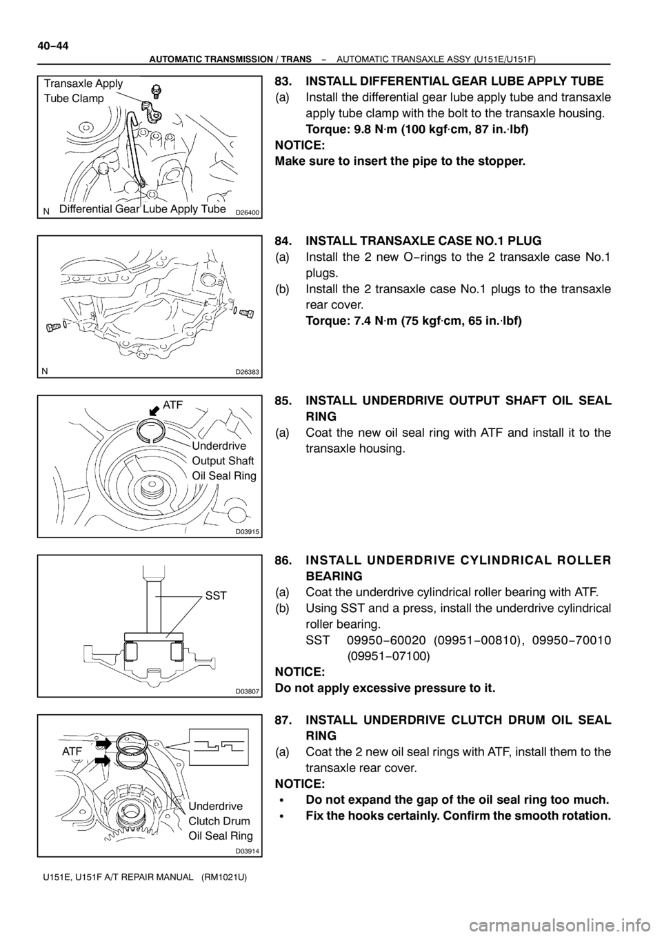
83. INSTALL DIFFERENTIAL GEAR LUBE APPLY TUBE
(a) Install the differential gear lube apply tube and transaxle
apply tube clamp with the bolt to the transaxle housing.
Torque: 9.8 N�m(100 kgf�cm, 87 in.�lbf)
NOTICE:
Make sure to insert the pipe to the stopper.
84. INSTALL TRANSAXLE CASE NO.1PLUG
(a) Install the 2 new O−rings to the 2 transaxle case No.1
plugs.
(b) Install the 2 transaxle case No.1 plugs to the transaxle
rear cover.
Torque: 7.4 N�m (75 kgf�cm, 65 in.�lbf)
85. INSTALL UNDERDRIVE OUTPUT SHAFT OIL SEAL
RING
(a) Coat the new oil seal ring with ATF and install it to the
transaxle housing.
86. INSTALL UNDERDRIVE CYLINDRICAL ROLLER
BEARING
(a) Coat the underdrive cylindrical roller bearing with ATF.
(b) Using SST and a press, install the underdrive cylindrical
roller bearing.
SST 09950−60020 (09951−00810), 09950−70010
(09951−07100)
NOTICE:
Do not apply excessive pressure to it.
87. INSTALL UNDERDRIVE CLUTCH DRUM OIL SEAL
RING
(a) Coat the 2 new oil seal rings with ATF, install them to the
transaxle rear cover.
NOTICE:
SDo not expand the gap of the oil seal ring too much.
SFix the hooks certainly. Confirm the smooth rotation.
Page 4876 of 5135

D26407
SST
Snap Ring
C89126
SST
D26467
Snap Ring
D26410
SST
40−46
− AUTOMATIC TRANSMISSION / TRANSAUTOMATIC TRANSAXLE ASSY (U151E/U151F)
U151E, U151F A/T REPAIR MANUAL (RM1021U)
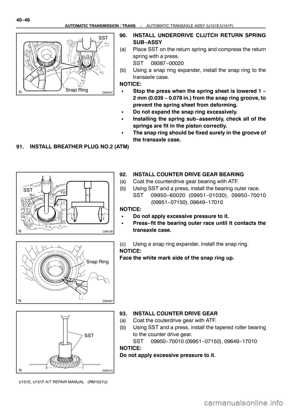
90. INSTALL UNDERDRIVE CLUTCH RETURN SPRING
SUB−ASSY
(a) Place SST on the return spring and compress the return
spring with a press.
SST 09387−00020
(b) Using a snap ring expander, install the snap ring to the
transaxle case.
NOTICE:
SStop the press when the spring sheet is lowered1−
2 mm (0.039−0.078 in.) from the snap ring groove, to
prevent the spring sheet from deforming.
SDo not expand the snap ring excessively.
SInstalling the spring sub−assembly, check all of the
springs are fit in the piston correctly.
SThe snap ring should be fixed surely in the groove of
the transaxle case.
91. INSTALL BREATHER PLUG NO.2 (ATM)
92. INSTALL COUNTER DRIVE GEAR BEARING
(a) Coat the counterdrive gear bearing with ATF.
(b) Using SST and a press, install the bearing outer race.
SST 09950−60020 (09951−01030), 09950−70010
(09951−07150), 09649−17010
NOTICE:
SDo not apply excessive pressure to it.
SPress−fit the bearing outer race until it contacts the
transaxle case.
(c) Using a snap ring expander, install the snap ring.
NOTICE:
Face the white mark side of the snap ring up.
93. INSTALL COUNTER DRIVE GEAR
(a) Coat the couterdrive gear with ATF.
(b) Using SST and a press, install the tapered roller bearing
to the counter drive gear.
SST 09950−70010 (09951−07150), 09649−17010
NOTICE:
Do not apply excessive pressure to it.
Page 4881 of 5135

D26591Rear Planetary Gear Assy
D03616
Snap Ring
D26413
Disc
Plate
D26452
A
− AUTOMATIC TRANSMISSION / TRANSAUTOMATIC TRANSAXLE ASSY (U151E/U151F)
40−51
U151E, U151F A/T REPAIR MANUAL (RM1021U)
Thrust bearing and bearing race diameter: mm (in.)
insideoutside
Thrust Bearing, A32.5 (1.28)56.5 (2.224)
Bearing Race, B40.2 (1.583)59.3 (2.335)
Thrust Bearing, C38.6 (1.520)59.7 (2.35)
Bearing Race, D38.6 (1.520)59.3 (2.335)
99. INSTALL REAR PLANETARY GEAR ASSY
(a) Install the rear planetary gear assy to the rear planetary
ring gear.
(b) Using a screwdriver, install the snap ring.
NOTICE:
Confirm the snap ring is fixed in the groove of the1st & re-
verse brake hub correctly.
100. INSTALL1ST & REVERSE BRAKE CLUTCH DISC
(a) Coat the 6 discs with ATF.
(b) Install the 6 plates and 6 discs.
NOTICE:
Be careful about the order of discs, plates and flange as-
sembly.
101. INSPECT PACK CLEARANCE OF FIRST & REVERSE
BRAKE
(a) Using vernier calipers, measure the distance between the
disc surface and the contact surface of the 2nd brake cyl-
inder and transaxle case(Dimension A).
(b) Select an appropriate flange so that the pack clearance
will meet the specified value.
Pack clearance:1.16−1.35 mm (0.0457−0.0531in.)
HINT:
Piston stroke = Dimension A−Flange thickness
Page 4882 of 5135

D03815
D26396Second Brake Piston Assy
D08058
Snap Ring
C929771−Way Clutch Sleeve Outer
40−52
− AUTOMATIC TRANSMISSION / TRANSAUTOMATIC TRANSAXLE ASSY (U151E/U151F)
U151E, U151F A/T REPAIR MANUAL (RM1021U)
Flange thickness: mm (in.)
MarkThicknessMarkThickness
11.8 (0.071)52.2 (0.087)
21.9 (0.075)62.3 (0.091)
32.0 (0.079)72.4 (0.094)
42.1 (0.083)82.5 (0.098)
(c) Install the flange.
102. INSTALL SECOND BRAKE PISTON ASSY
(a) Install the second brake piston assy to the transaxle case.
(b) Install the snap ring and measure the inside diameter.
Inside diameter: More than167 mm (6.57 in.)
NOTICE:
SBecause the taper snap ring has the positioning
direction, check it when installing.
SWhen the diameter does not meet the specified value,
replace the snap ring with new one.
SAfter assembling, confirm that there is no clearance
between the second brake cylinder and the fitting sur-
face of the cylinder in the transaxle case.
103. INSTALL1WAY CLUTCH SLEEVE OUTER
(a) Install the 1−way clutch sleeve outer to the 2nd brake cyl-
inder assy.
NOTICE:
Check the positioning direction of the outer sleeve.