Page 255 of 5135
A79094
*1: LHD
*2: RHD
*3: SEDAN
*4: LIFT BACK
*5: WAGON IE36
IR11 G±W
(*1)
G±W
(*2)G±W
G±W(*1)
(*2)
1
2DA DC
DM
1 210Driver Side J/B
E10STPECM
19
G±W
G±W
G±WG±W
G±W
G±W
G±W
G±W J30 C
BJ30 J30
J31
J31
B CC
2
1 R±W
IR1 2 IE3 11
DA22
STOP
DN1Driver
Side J/BCH20
High Mounted
Stop Light
J32
Junction
Connector W±B (*1)(*2) R±W
R±W
(*1)(*2) R±W(*3)
(*3)
C(*4, *5)
(*4, *5)
(*4, *5)
(*4)
(*5)
6 4 1
6 5 21 4 7
3 3 6 (*3)
(*4)
(*5)(*3)
(*4)
(*5)
(*3)
(*4)
(*5)(*3)
(*4)
(*5) R13
Rear
Combination
Light LHR14
Rear
Combination
Light RH Junction
ConnectorN8
Noise
FilterBD1 1
BF1 3
BE1 1L
G±W
G±W
1
2 H20
High
Mounted
Stop Light(*4)
(*4)(*5)
L
W±B
W±B (*4)(*5)
(*5)
(*4) (*4)
(*5)
(*4) (*5)
(*5)(*4, *5) W±B W±B
W±B
W±BW±B W±B
(*3)
W±B
(*3)W±B W±B
W±B
(*4, *5)
W±B Junction
Connector
Junction
Connector Engine
Room
J/B No.4 B±G
B±GALT 2
1
4B 14D
FL MAIN 1
J31 J30 B
CBD1
BF1BG1
J33
J34 BE1
BG14
A
A 2
2
3 4
Battery
BS
BTBX S13
Stop Light
Switch1 05±116
± DIAGNOSTICSSFI SYSTEM (1ZZ±FE/3ZZ±FE)
AVENSIS REPAIR MANUAL (RM1018E)
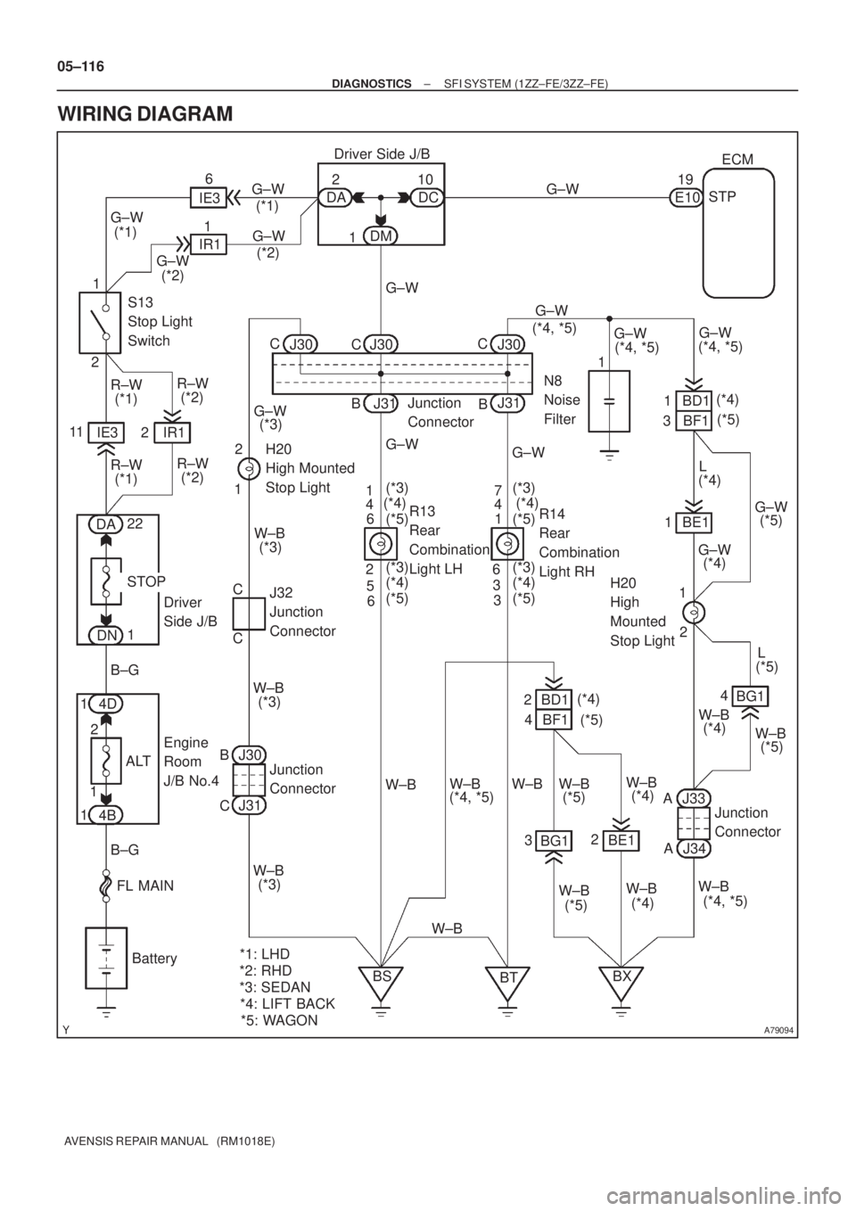
WIRING DIAGRAM
Page 258 of 5135

A63991
ECM
C2
Camshaft Timing
Oil Control Valve
2
1
Y±B
W±G
OCV+
OCV±
15
14
E13
E13
05±112
±
DIAGNOSTICS SFI SYSTEM(1ZZ±FE/3ZZ±FE)
AVENSIS REPAIR MANUAL (RM1018E)
DTCP1349VVT SYSTEM MALFUNCTION (BANK 1)
CIRCUIT DESCRIPTION
VVT system controls the intake valve timing to proper timing in response to\
driving condition.
The ECM controls the oil control valve (OCV) to make the intake valve timing properly, oil pressure regulated
by the OCV is supplied to the valiable valve timing (VVT) controller, and then the VVT controller changes
relative position between the camshaft and the crankshaft.
DTC No.DTC Detecting ConditionTrouble Area
P1349
Condition (a) or (b) continues with engine speed at 400 to
4,000 rpm after the engine is warmed up
(a)Valve timing does not change from the current valve timing
(b)Current valve timing is fixed� Valve timing
� OCV
� VVT controller assembly
� ECM
WIRING DIAGRAM
INSPECTION PROCEDURE
HINT:
Read freeze frame data using \f���� ����\b�\f��\f�
� Freeze frame data records the engine conditions when
a malfunction is detected. When troubleshooting, it is useful for determi\
ning whether the vehicle was running
or stopped, the engine was warmed up or not, the air±fuel ratio was lea\
n or rich, etc. at the time of the mal-
function.
1CHECK VALVE TIMING (See page 14±49)
NGADJUST VALVE TIMING(See page 14±49)
OK
05C6F±01
Page 263 of 5135
������A79093
ECM
EH W±B E13
IGT1
IGF
E13
E13
E13
E13 23 IGT2
IGT3
IGT4
8
10
11
R±W
3
2
1
I1
Ignition Coil and
Igniter No.1
I2
Ignition Coil and
Igniter No.2
I3
Ignition Coil and
Igniter No.3
I4
Ignition Coil and
Igniter No.4
R±B
W±B 4 3
2
B±R
1
1
1
B±R
R±B
33
2
2
L±YW±R
W±R W±R
4 4 4
W±B
W±B
W±B
W±B
R±B
W±R
R±B R±B
From Terminal 3
of IG2 Relay
(See Page 05±124)
W±B LG±B
P
W±R
W±R
W±R 9
R±B 1N2
Noise
Filter R±B
8 EA1
±
DIAGNOSTICS SFI SYSTEM (1ZZ±FE/3ZZ±FE)
05±105
AVENSIS REPAIR MANUAL (RM1018E)
WIRING DIAGRAM
Page 269 of 5135
A58697
Intake Air
Chamber
Throttle Valve
To Cylinder
ISC Valve
Valve
ECM
Signal From
Air
Cleaner
From
Terminal 2 of
EFI No.1 Fuse
(See Page 05±124)
A79101
2 VISC DUTY1
GND 3
I10
ISC Valve
G±R5
E13 RSDECM
B±R 12
EA1 B±R
W±B7
E13 E01
W±B
EG
05±100
±
DIAGNOSTICS SFI SYSTEM (1ZZ±FE/3ZZ±FE)
AVENSIS REPAIR MANUAL (RM1018E)
DTC P0505 IDLE CONTROL SYSTEM MALFUNCTION
CIRCUIT DESCRIPTION
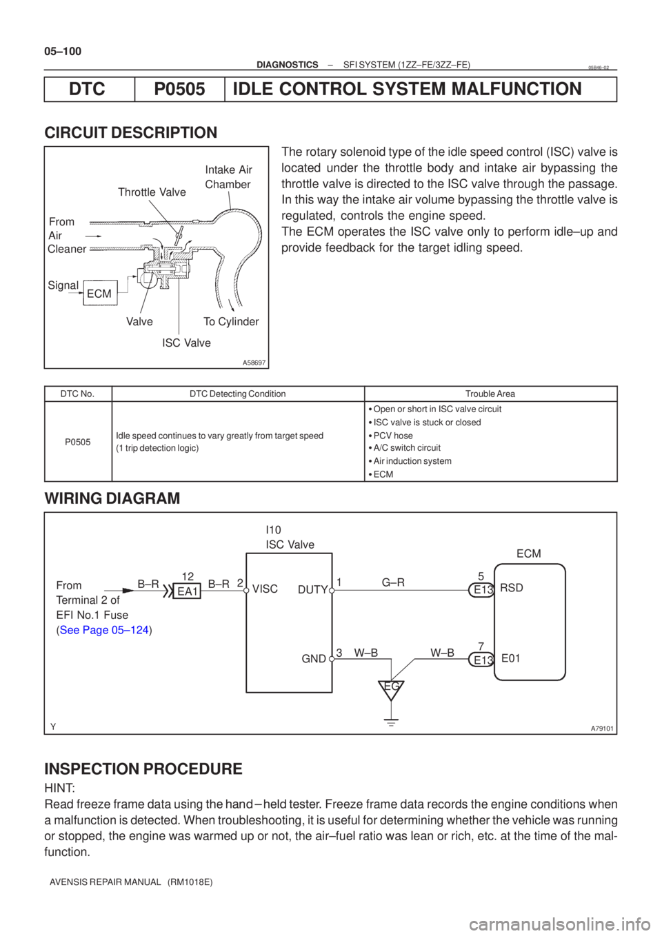
The rotary solenoid type of the idle speed control (ISC) valve is
located under the throttle body and intake air bypassing the
throttle valve is directed to the ISC valve through the passage.
In this way the intake air volume bypassing the throttle valve is
regulated, controls the engine speed.
The ECM operates the ISC valve only to perform idle±up and
provide feedback for the target idling speed.
DTC No.DTC Detecting ConditionTrouble Area
P0505Idle speed continues to vary greatly from target speed
(1 trip detection logic)
� Open or short in ISC valve circuit
� ISC valve is stuck or closed
� PCV hose
� A/C switch circuit
� Air induction system
� ECM
WIRING DIAGRAM
INSPECTION PROCEDURE
HINT:
Read freeze frame data using \f�� �� ����\b� \f��\f�
� Freeze frame data records the engine conditions when
a malfunction is detected. When troubleshooting, it is useful for determi\
ning whether the vehicle was running
or stopped, the engine was warmed up or not, the air±fuel ratio was lea\
n or rich, etc. at the time of the mal-
function.
05B46±02
Page 272 of 5135
A79413
From
Speed SensorSkid
Control
ECU4±Pulse
Combination
Meter4±Pulse
ECM
A79092
C11
Combination Meter
Junction Connector
17
V±W
E10ECM
V±W
SPD 18
J10
J20 H
*1*2
*1: LHD
*2: RHD J20 J10
*1 *2 HHH 05±98
± DIAGNOSTICSSFI SYSTEM (1ZZ±FE/3ZZ±FE)
AVENSIS REPAIR MANUAL (RM1018E)
DTC P0500 VEHICLE SPEED SENSOR MALFUNCTION
CIRCUIT DESCRIPTION
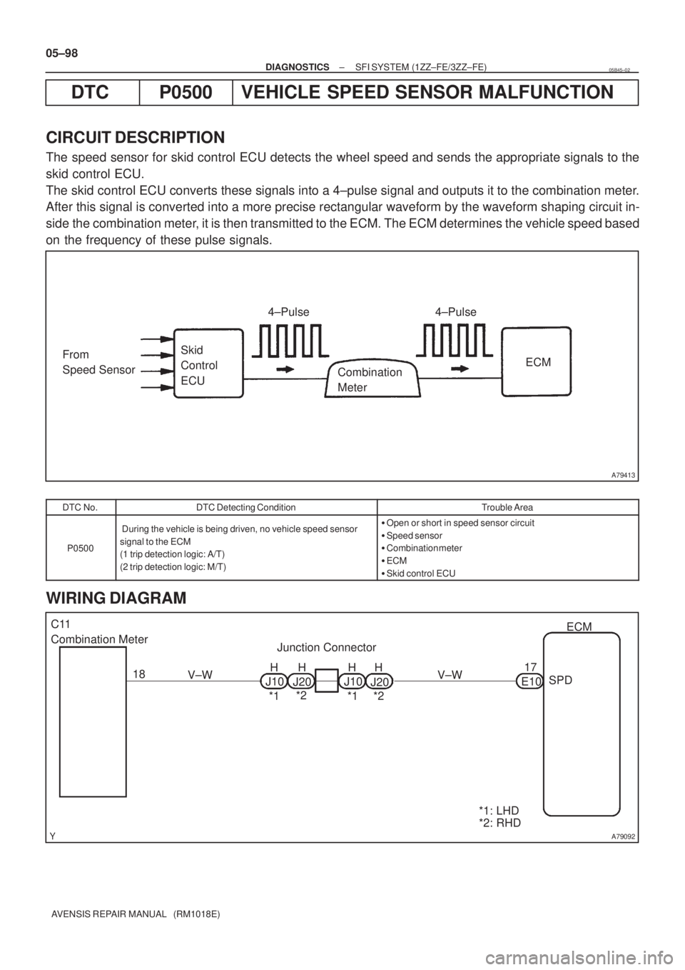
The speed sensor for skid control ECU detects the wheel speed and sends the appropriate signals to the
skid control ECU.
The skid control ECU converts these signals into a 4±pulse signal and outputs it to the combination meter.
After this signal is converted into a more precise rectangular waveform by the waveform shaping circuit in-
side the combination meter, it is then transmitted to the ECM. The ECM determines the vehicle speed based
on the frequency of these pulse signals.
DTC No.DTC Detecting ConditionTrouble Area
P0500
During the vehicle is being driven, no vehicle speed sensor
signal to the ECM
(1 trip detection logic: A/T)
(2 trip detection logic: M/T)�Open or short in speed sensor circuit
�Speed sensor
�Combination meter
�ECM
�Skid control ECU
WIRING DIAGRAM
05B45±02
Page 274 of 5135
A79073
From
Terminal 3 of
EFI Relay
(See Page 05±124)B±W
EA113
B±W 2V5
VSV for EVAP
1 W±G E1312
EVP1ECM
Engine Room R/B No.4 EFI No.2
4 1 2
B±W
4
05±94
±
DIAGNOSTICS SFI SYSTEM (1ZZ±FE/3ZZ±FE)
AVENSIS REPAIR MANUAL (RM1018E)
DTC P0443 EVAPORATIVE EMISSION CONTROL SYSTEM PURGE CONTROL VALVE CIRCUIT
MALFUNCTION
CIRCUIT DESCRIPTION
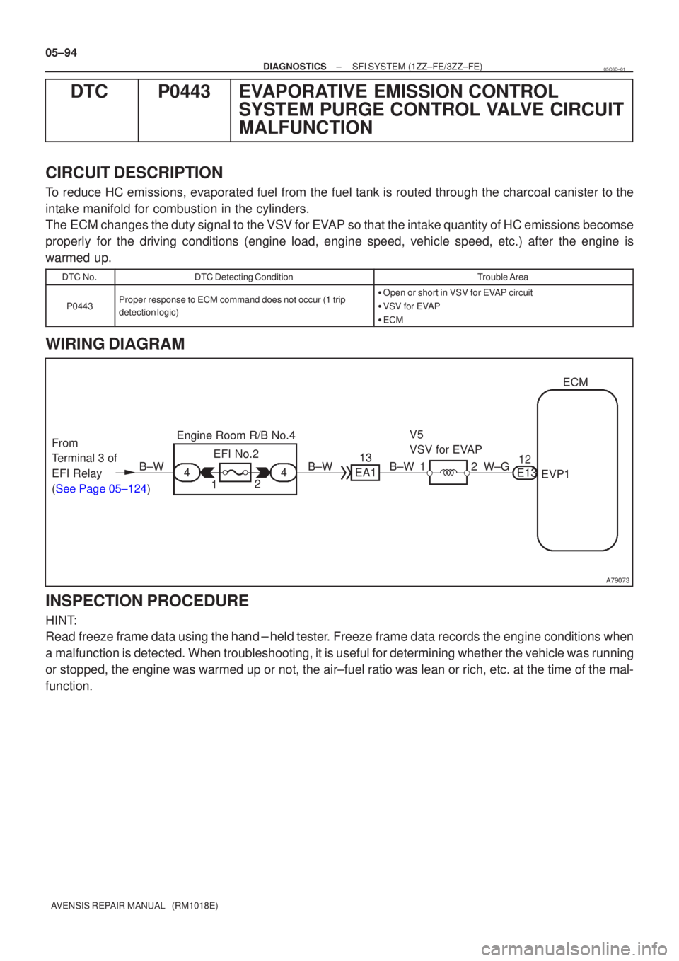
To reduce HC emissions, evaporated fuel from the fuel tank is routed through the charcoal canister to the
intake manifold for combustion in the cylinders.
The ECM changes the duty signal to the VSV for EVAP so that the intake quantity of HC emissions becomse
properly for the driving conditions (engine load, engine speed, vehicle speed, \
etc.) after the engine is
warmed up.
DTC No.DTC Detecting ConditionTrouble Area
P0443Proper response to ECM command does not occur (1 trip
detection logic)�Open or short in VSV for EVAP circuit
� VSV for EVAP
� ECM
WIRING DIAGRAM
INSPECTION PROCEDURE
HINT:
Read freeze frame data using \f�� �� ����\b� \f��\f�
� Freeze frame data records the engine conditions when
a malfunction is detected. When troubleshooting, it is useful for determi\
ning whether the vehicle was running
or stopped, the engine was warmed up or not, the air±fuel ratio was lea\
n or rich, etc. at the time of the mal-
function.
05C6D±01
Page 281 of 5135
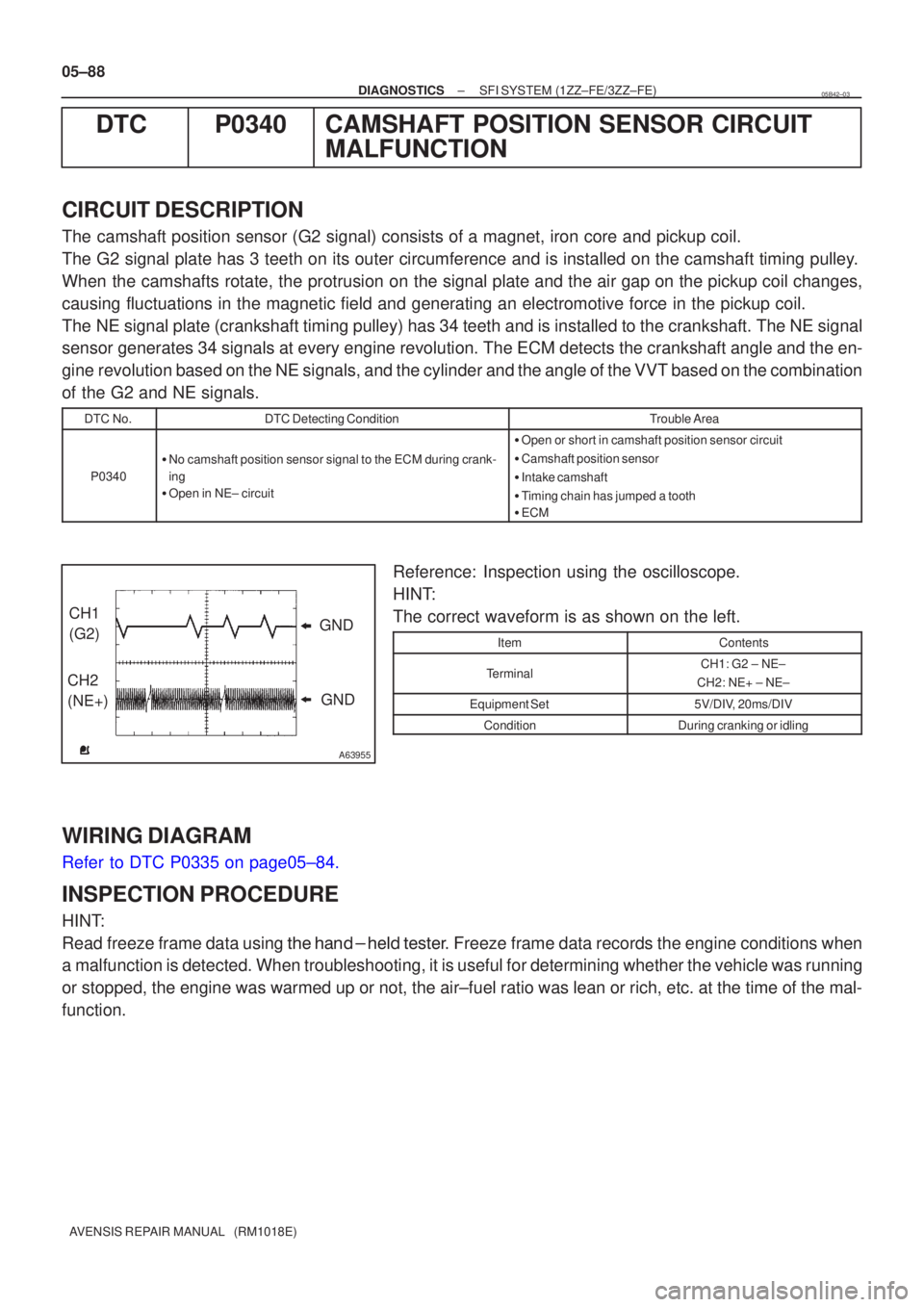
A63955
GND
CH1
(G2)
CH2
(NE+) GND
05±88
±
DIAGNOSTICS SFI SYSTEM(1ZZ±FE/3ZZ±FE)
AVENSIS REPAIR MANUAL (RM1018E)
DTCP0340CAMSHAFT POSITION SENSOR CIRCUIT MALFUNCTION
CIRCUIT DESCRIPTION
The camshaft position sensor (G2 signal) consists of a magnet, iron core \
and pickup coil.
The G2 signal plate has 3 teeth on its outer circumference and is instal\
led on the camshaft timing pulley.
When the camshafts rotate, the protrusion on the signal plate and the air gap on the pickup coil changes,
causing fluctuations in the magnetic field and generating an electromoti\
ve force in the pickup coil.
The NE signal plate (crankshaft timing pulley) has 34 teeth and is instal\
led to the crankshaft. The NE signal
sensor generates 34 signals at every engine revolution. The ECM detects \
the crankshaft angle and the en-
gine revolution based on the NE signals, and the cylinder and the angle of the VVT based on the combination
of the G2 and NE signals.
DTC No.DTC Detecting ConditionTrouble Area
P0340
�No camshaft position sensor signal to the ECM during crank-
ing
� Open in NE± circuit
�Open or short in camshaft position sensor circuit
� Camshaft position sensor
� Intake camshaft
� Timing chain has jumped a tooth
� ECM
Reference: Inspection using the oscilloscope.
HINT:
The correct waveform is as shown on the left.
ItemContents
TerminalCH1: G2 ± NE±
CH2: NE+ ± NE±
Equipment Set5V/DIV, 20ms/DIV
ConditionDuring cranking or idling
WIRING DIAGRAM
Refer to DTC P0335 on page05±84.
INSPECTION PROCEDURE
HINT:
Read freeze frame data using \f�� �� ����\b� \f��\f�
� Freeze frame data records the engine conditions when
a malfunction is detected. When troubleshooting, it is useful for determi\
ning whether the vehicle was running
or stopped, the engine was warmed up or not, the air±fuel ratio was lea\
n or rich, etc. at the time of the mal-
function.
05B42±03
Page 285 of 5135
A79089
C1
Camshaft Position Sensor(Shielded)
1 2ECM
(Shielded) 1
2
EHR
NE+NE± G2 W
G C6
Crankshaft Position Sensor
R RE13
E13
E1326
34
27
BR E
J12
Junction
ConnectorE E
± DIAGNOSTICSSFI SYSTEM (1ZZ±FE/3ZZ±FE)
05±85
AVENSIS REPAIR MANUAL (RM1018E)
WIRING DIAGRAM
INSPECTION PROCEDURE
HINT:
�Read freeze frame data using ��� �� ������ �����
� Freeze frame data records the engine conditions
when a malfunction is detected. When troubleshooting, it is useful for determining whether the vehicle
was running or stopped, the engine was warmed up or not, the air±fuel ratio was lean or rich, etc. at
the time of the malfunction.
�Perform troubleshooting on ºDTC P0335º first. If no trouble is found, troubleshoot the following me-
chanical system.