Page 288 of 5135

���
A05134
2.2V
A79088
K1
Knock SensorECM
FKN+
E12 (Shielded)
1EB1
11
W
E122
FKN± B
EH J12
J13
Junction
Connector EDEB1 2WB2
BR
BR J12 J13E D
± DIAGNOSTICSSFI SYSTEM (1ZZ±FE/3ZZ±FE)
05±81
AVENSIS REPAIR MANUAL (RM1018E)
DTC P0325 KNOCK SENSOR 1 CIRCUIT MALFUNCTION
(BANK 1)
CIRCUIT DESCRIPTION
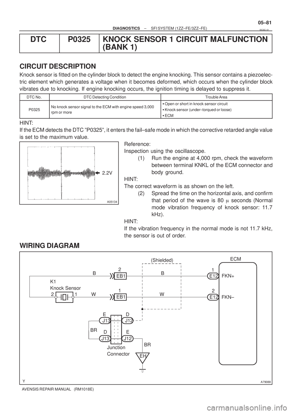
Knock sensor is fitted on the cylinder block to detect the engine knocking. This sensor contains a piezoelec-
tric element which generates a voltage when it becomes deformed, which occurs when the cylinder block
vibrates due to knocking. If engine knocking occurs, the ignition timing is delayed to suppress it.
DTC No.DTC Detecting ConditionTrouble Area
P0325No knock sensor signal to the ECM with engine speed 3,000
rpm or more�Open or short in knock sensor circuit
�Knock sensor (under±torqued or loose)
�ECM
HINT:
If the ECM detects the DTC ºP0325º, it enters the fail±safe mode in which the corrective retarded angle value
is set to the maximum value.
Reference:
Inspection using the oscillascope.
(1) Run the engine at 4,000 rpm, check the waveform
between terminal KNKL of the ECM connector and
body ground.
HINT:
The correct waveform is as shown on the left.
(2) Spread the time on the horizontal axis, and confirm
that period of the wave is 80 � seconds (Normal
mode vibration frequency of knock sensor: 11.7
kHz).
HINT:
If the vibration frequency in the normal mode is not 11.7 kHz,
the sensor is out of order.
WIRING DIAGRAM
05C6C±01
Page 292 of 5135

05C6P±01
A66714
E13 E12 E10
E9
05±166
± DIAGNOSTICSSFI SYSTEM (1AZ±FE)
AVENSIS REPAIR MANUAL (RM1018E)
TERMINALS OF ECM
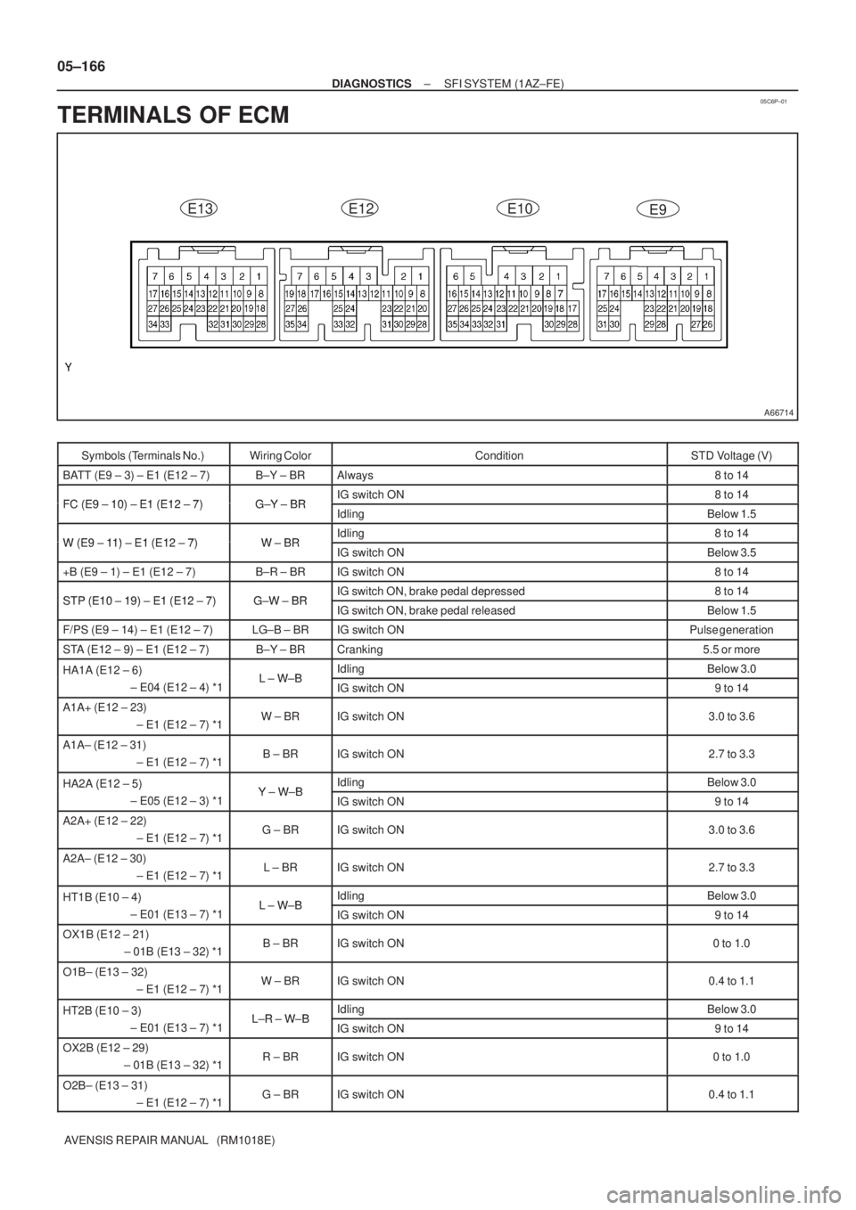
Symbols (Terminals No.)Wiring ColorConditionSTD Voltage (V)
BATT (E9 ± 3) ± E1 (E12 ± 7)B±Y ± BRAlways8 to 14
FC (E9 10) E1 (E12 7)GY BRIG switch ON8 to 14FC (E9 ± 10) ± E1 (E12 ± 7)G±Y ± BRIdlingBelow 1.5
W (E9 11) E1 (E12 7)WBRIdling8 to 14W (E9 ± 11) ± E1 (E12 ± 7)W ± BRIG switch ONBelow 3.5
+B (E9 ± 1) ± E1 (E12 ± 7)B±R ± BRIG switch ON8 to 14
STP (E10 19) E1 (E12 7)GW BRIG switch ON, brake pedal depressed8 to 14STP (E10 ± 19) ± E1 (E12 ± 7)G±W ± BRIG switch ON, brake pedal releasedBelow 1.5
F/PS (E9 ± 14) ± E1 (E12 ± 7)LG±B ± BRIG switch ONPulse generation
STA (E12 ± 9) ± E1 (E12 ± 7)B±Y ± BRCranking5.5 or more
HA1A (E12 ± 6) LWBIdlingBelow 3.0HA1A (E12 6)
± E04 (E12 ± 4) *1L ± W±BIG switch ON9 to 14
A1A+ (E12 ± 23)
± E1 (E12 ± 7) *1W ± BRIG switch ON3.0 to 3.6
A1A± (E12 ± 31)
± E1 (E12 ± 7) *1B ± BRIG switch ON2.7 to 3.3
HA2A (E12 ± 5) YWBIdlingBelow 3.0HA2A (E12 5)
± E05 (E12 ± 3) *1Y ± W±BIG switch ON9 to 14
A2A+ (E12 ± 22)
± E1 (E12 ± 7) *1G ± BRIG switch ON3.0 to 3.6
A2A± (E12 ± 30)
± E1 (E12 ± 7) *1L ± BRIG switch ON2.7 to 3.3
HT1B (E10 ± 4) LWBIdlingBelow 3.0HT1B (E10 4)
± E01 (E13 ± 7) *1L ± W±BIG switch ON9 to 14
OX1B (E12 ± 21)
± 01B (E13 ± 32) *1B ± BRIG switch ON0 to 1.0
O1B± (E13 ± 32)
± E1 (E12 ± 7) *1W ± BRIG switch ON0.4 to 1.1
HT2B (E10 ± 3) LR WBIdlingBelow 3.0HT2B (E10 3)
± E01 (E13 ± 7) *1L±R ± W±BIG switch ON9 to 14
OX2B (E12 ± 29)
± 01B (E13 ± 32) *1R ± BRIG switch ON0 to 1.0
O2B± (E13 ± 31)
± E1 (E12 ± 7) *1G ± BRIG switch ON0.4 to 1.1
Page 305 of 5135

A81014
4 D5
DLC3
CGTC13
W±BCBW±L20
E9TCECM
W±L
W±B J8
J/C
BB
J16
J/C
A
IP
IOCenter J/B
CA 36
A(RHD) W±B
(RHD)
(LHD)W±B
(LHD) (LHD)W±L
(LHD)
W±L W±L
(RHD)
(RHD) J21D
J20BDB DC173 Driver Side J/B
3 2 1 45678
9 1 0 111 21 31 41 51 6
DLC3
A04550
CG (±)TC (+)
DLC3
± DIAGNOSTICSSFI SYSTEM (1ZZ±FE/3ZZ±FE)
05±141
AVENSIS REPAIR MANUAL (RM1018E)
TC TERMINAL CIRCUIT
CIRCUIT DESCRIPTION
Terminals TC and CG are located in the DLC3. When connecting these terminals, DTCs in normal mode or
check mode can be read through the CHK ENG flashing in the combination meter.
WIRING DIAGRAM
INSPECTION PROCEDURE
HINT:
�Even though terminal TC is not connected to terminal CG, the CHK ENG blinks.
�For the above phenomenon, an open or short in the wire harness, or malfunction inside the ECM is
the likely cause.
1 CHECK DLC3(TC VOLTAGE)
(a) Turn the ignition switch ON.
(b) Measure the voltage between the terminals of the DLC3.
Standard:
Symbols (Terminal No.)Specified condition
TC (13) ± CG (4)9 to 14 V
OK Go to step 3
NG
05C6K±01
Page 307 of 5135
A81015
Engine
Room
R/B No. 1
Engine
Room
J/B No. 1W
9ECM
W
E9 11
1 2
B±W22 1
4A
Battery4
2I13
Ignition
Switch
DH 6
B±R B±R
C11
Combination
Meter Assy
Check
Engine
Warning
Light AM2
IG2
AM2
Driver
Side
J/B
FL MAINEngine
Room
J/B
No. 4
4BB±G 1A 1B±R
IE41
(LHD)IP11
(RHD)
18 DA
J8C
(LHD)J26A
(RHD)J8C
(LHD)J26A
(RHD) J/CB±W IGN
1
1
B±G
± DIAGNOSTICSSFI SYSTEM (1ZZ±FE/3ZZ±FE)
05±139
AVENSIS REPAIR MANUAL (RM1018E)
CHECK ENGINE WARNING LIGHT CIRCUIT
CIRCUIT DESCRIPTION
If the ECM detects a trouble, the CHK ENG is illuminated. At this time, the ECM records a DTC in the memory.
WIRING DIAGRAM
INSPECTION PROCEDURE
HINT:
Troubleshoot each trouble symptom in accordance with the chart below .
CHK ENG remains onStart inspection from step 1
CHK ENG is not illuminatedStart inspection from step 3
05C6J±01
Page 310 of 5135
A79100
I13
Ignition Switch
45
B±RB±Y
6
1
ST
2
6Fuse
Block
B±W
B±R B±R
1
1
IP1 IE4
(*1)
(*2)
B±R
1
2
1
1A 1AM2Engine
Room
R/B No.1
and
Engine
Room
J/B No.1
B±GB±Y
55
ST
Relay 51
32
55J13J12 BB
CA9
6N1
Neutral
Start
SwitchB±Y
(*4)
ECM
STA B±Y9
E12 B±W
(*3)
B±Y
(*3)
A J13 J12
J12
Junction
Connector
Engine
Room
J/B No.4 4A 1
1
4B
B±G
FL MAIN
BatteryB±R
IJDriver
Side R/B
BW±B
Driver
Side J/B DJ 2
DA 9
W±B B
S4
S511
Stater IK1
7*1: LHD
*2: RHD
*3: A/T
*4: M/T 05±136
± DIAGNOSTICSSFI SYSTEM (1ZZ±FE/3ZZ±FE)
AVENSIS REPAIR MANUAL (RM1018E)
WIRING DIAGRAM
Page 313 of 5135

A79082
53G±Y
L±B E9 10
4
5 W±B
BR F25
Fuel Pump ECM
B±W 12
FC
C8
Circuit
Opening Relay
From
Terminal 3 of
EFI Relay
(See Page 05±124)
G±Y
B±W
B±W
IB1 10 IC3
6
±
DIAGNOSTICS SFI SYSTEM(1ZZ±FE/3ZZ±FE)
05±131
AVENSIS REPAIR MANUAL (RM1018E)
FUEL PUMP CONTROL CIRCUIT
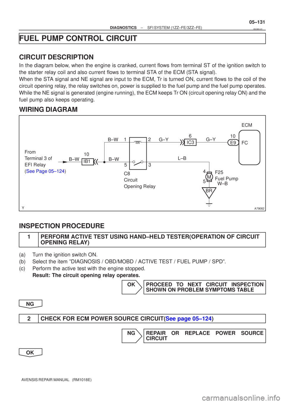
CIRCUIT DESCRIPTION
In the diagram below, when the engine is cranked, current flows from terminal ST of the igni\
tion switch to
the starter relay coil and also current flows to terminal STA of the ECM (STA signal).
When the STA signal and NE signal are input to the ECM, Tr is turned ON, current flows to the coil of the
circuit opening relay, the relay switches on, power is supplied to the fuel pump and the fuel p\
ump operates.
While the NE signal is generated (engine running), the ECM keeps Tr ON (circuit opening relay ON) and the
fuel pump also keeps operating.
WIRING DIAGRAM
INSPECTION PROCEDURE
1PERFORM ACTIVE TEST USING HAND±HELD TESTER(OPERATION OF CIRCUIT
OPENING RELAY)
(a)Turn the ignition switch ON.
(b)Select the item ºDIAGNOSIS / OBD/MOBD / ACTIVE TEST / FUEL PUMP / SPD\
º.
(c)Perform the active test with the engine stopped.
Result: The circuit opening relay operates.
OKPROCEED TO NEXT CIRCUIT INSPECTIONSHOWN ON PROBLEM SYMPTOMS TABLE
NG
2CHECK FOR ECM POWER SOURCE CIRCUIT(See page 05±124)
NG REPAIR OR REPLACE POWER SOURCE CIRCUIT
OK
05C6H±01
Page 318 of 5135
A79085
IE4
IP1
1 1 B±R
4
6
I13
Ignition Switch
B±RDH IGN
16 DL
2
Driver Side J/B
B±W
B
B±R 4
4
1
IG2
Relay
2
3 Engine Room
R/B No.4 ECM
4 4
5
111 B±Y
2
1 112
2
EFI
IG2
AM2
1A B±G Engine Room
R/B No.1 and
Engine Room
J/B No.1 R±B
EA1
8 8
MREL
E9
GR
IE1
2
GR
4
4
51
32 EFI
Relay
4 4
Engine Room
R/B No.4
W±B
W±B
1
1+B
E9
B±R
EC
To Injector
(See page 05±73)
To Ignition Coil
and Igniter
(See page 05±103)
B±R
B±R
EA1
IK1
8
12
Battery
FL MAIN
B±G Engine Room
J/B No.4
4A
4B
1
1
R±B
W±B EFI
No.1
Engine Room
R/B No.4
1 B±W
4
2 4
18
DA B±W
A
J26
Junction Connector
E
J27 B±W
E9IGSW
9
(*2) J8
Junction Connector
(*1) B±W
EH E1
7
E12
BR
(*2)
(*1)
C C
*1: RHD *2: LHD
(*1)
(*2)
±
DIAGNOSTICS SFI SYSTEM (1ZZ±FE/3ZZ±FE)
05±125
AVENSIS REPAIR MANUAL (RM1018E)
WIRING DIAGRAM
Page 324 of 5135

���\b�A79115
Reference (Bank 1 Sensor 2 System Drawing)Heated Oxygen Sensor
EFI Relay
Heater
SensorOX1B HT1BECM
From
Battery EFI Fuse
O1B±
MREL
EFI No.2 Fuse
05±218
±
DIAGNOSTICS SFI SYSTEM(1AZ±FE)
AVENSIS REPAIR MANUAL (RM1018E)
DTCP0141/27OXYGEN SENSOR HEATER CIRCUIT MALFUNCTION (BANK 1 SENSOR 2)
DTCP0161/29OXYGEN SENSOR HEATER CIRCUIT (BANK 2 SENSOR 2)
CIRCUIT DESCRIPTION
Refer to DTC P0136/27 on page 05±211.
HINT:
The ECM provides a pulse width modulated control circuit to adjust current \
through the heater. The heated
oxygen sensor heater circuit uses a relay on the B+ side of the circuit.
DTC No.DTC Detection ConditionTrouble Area
P0141/27
Heated current is 0.2 A or less when heater operates
(1 trip detection logic)�Open or short in heater circuit of heated oxygen sensor
� Heated oxygen sensor heater
P0141/27
P0161/29When heater operates, heated current exceeds 2 A
(1 trip detection logic)
yg
�EFI relay
� ECM
HINT:
�Bank 1 refers to the bank that includes cylinder No.1.
�Bank 2 refers to the bank that does not include cylinder No.1.
�Sensor 1 refers to the sensor closest to the engine assembly.
�Sensor 2 refers to the sensor farthest away from the engine assembly.
WIRING DIAGRAM
Refer to DTC P0136/27 on page 05±211.
INSPECTION PROCEDURE
HINT:
�If different DTCs that are related to a different system are output simultaneously while terminal E2 is
used as a ground terminal, terminal E2 may be open.
�Read freeze frame data using �
\f
���
\f�� �\f��\f�� Freeze frame data records the engine conditions
when a malfunction is detected. When troubleshooting, it is useful for d\
etermining whether the vehicle
was running or stopped, the engine was warmed up or not, the air±fuel ra\
tio was lean or rich, etc. at
the time of the malfunction.
05C6Y±01