Page 215 of 5135

±
DIAGNOSTICS SFI SYSTEM(1ZZ±FE/3ZZ±FE)
05±65
AVENSIS REPAIR MANUAL (RM1018E)
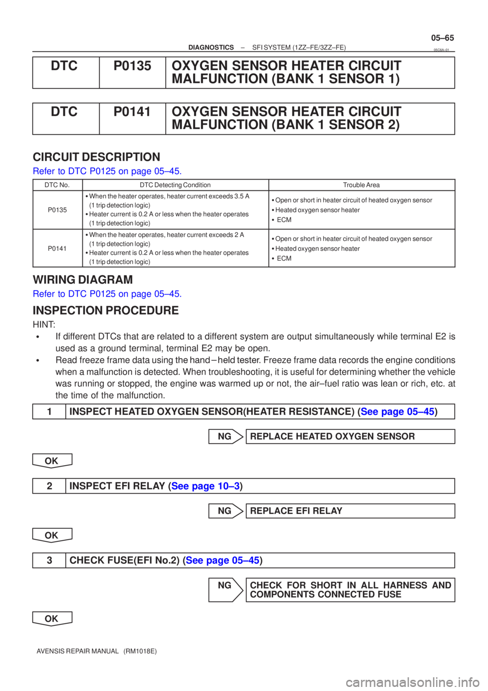
DTCP0135OXYGEN SENSOR HEATER CIRCUIT
MALFUNCTION (BANK 1 SENSOR 1)
DTCP0141OXYGEN SENSOR HEATER CIRCUIT MALFUNCTION (BANK 1 SENSOR 2)
CIRCUIT DESCRIPTION
Refer to DTC P0125 on page 05±45.
DTC No.DTC Detecting ConditionTrouble Area
P0135
�When the heater operates, heater current exceeds 3.5 A
(1 trip detection logic)
� Heater current is 0.2 A or less when the heater operates
(1 trip detection logic)�Open or short in heater circuit of heated oxygen sensor
� Heated oxygen sensor heater
� ECM
P0141
�When the heater operates, heater current exceeds 2 A
(1 trip detection logic)
� Heater current is 0.2 A or less when the heater operates
(1 trip detection logic)�Open or short in heater circuit of heated oxygen sensor
� Heated oxygen sensor heater
� ECM
WIRING DIAGRAM
Refer to DTC P0125 on page 05±45.
INSPECTION PROCEDURE
HINT:
�If different DTCs that are related to a different system are output simultaneously while terminal E2 is
used as a ground terminal, terminal E2 may be open.
�Read freeze frame data using \f���� ����\b�\f��\f�
� Freeze frame data records the engine conditions
when a malfunction is detected. When troubleshooting, it is useful for d\
etermining whether the vehicle
was running or stopped, the engine was warmed up or not, the air±fuel ra\
tio was lean or rich, etc. at
the time of the malfunction.
1INSPECT HEATED OXYGEN SENSOR(HEATER RESISTANCE) (See page 05±45)
NG REPLACE HEATED OXYGEN SENSOR
OK
2INSPECT EFI RELAY (See page 10±3)
NG REPLACE EFI RELAY
OK
3CHECK FUSE(EFI No.2) (See page 05±45)
NG CHECK FOR SHORT IN ALL HARNESS AND COMPONENTS CONNECTED FUSE
OK
05C6A±01
Page 217 of 5135

05±60
±
DIAGNOSTICS SFI SYSTEM(1ZZ±FE/3ZZ±FE)
AVENSIS REPAIR MANUAL (RM1018E)
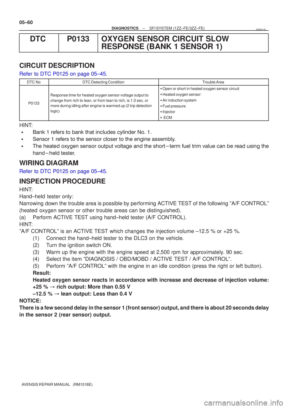
DTCP0133OXYGEN SENSOR CIRCUIT SLOW RESPONSE (BANK 1 SENSOR 1)
CIRCUIT DESCRIPTION
Refer to DTC P0125 on page 05±45.
DTC NoDTC Detecting ConditionTrouble Area
P0133
Response time for heated oxygen sensor voltage output to
change from rich to lean, or from lean to rich, is 1.0 sec. or
more during idling after engine is warmed up (2 trip detection
logic)
�Open or short in heated oxygen sensor circuit
� Heated oxygen sensor
� Air induction system
� Fuel pressure
� Injector
� ECM
HINT:
�� ����
�
����
���� ������\f
������\f
������
��
������
�
������
�
��������
�����
����
��
�
���
�\b�
�
�
\f����
��
�������������� �
�\f��
�������
����
������ ��
� �
�
\f�������
� �\f��
�\f�
��
��
WIRING DIAGRAM
Refer to DTC P0125 on page 05±45.
INSPECTION PROCEDURE
HINT:
Hand±held tester only:
Narrowing down the trouble area is possible by performing ACTIVE TEST of the following \
ºA/F CONTROLº
(heated oxygen sensor or other trouble areas can be distinguished).
(a) Perform ACTIVE TEST using hand±held tester (A/F CONTROL).
HINT:
ºA/F CONTROLº is an ACTIVE TEST which changes the injection volume\
±12.5 % or +25 %.
(1) Connect the hand±held tester to the DLC3 on the vehicle.
(2) Turn the ignition switch ON.
(3) Warm up the engine with the engine speed at 2,500 rpm for approximately. 90 sec.
(4) Select the item ºDIAGNOSIS / OBD/MOBD / ACTIVE TEST / A/F CONTROLº\
.
(5) Perform ºA/F CONTROLº with the engine in an idle condition (press\
the right or left button).
Result:
Heated oxygen sensor reacts in accordance with increase and decrease of injection volume:
+25 % � rich output: More than 0.55 V
±12.5 % � lean output: Less than 0.4 V
NOTICE:
There is a few second delay in the sensor 1 (front sensor) output, and ther\
e is about 20 seconds delay
in the sensor 2 (rear sensor) output.
05B3W±02
Page 222 of 5135

05±54
±
DIAGNOSTICS SFI SYSTEM(1ZZ±FE/3ZZ±FE)
AVENSIS REPAIR MANUAL (RM1018E)
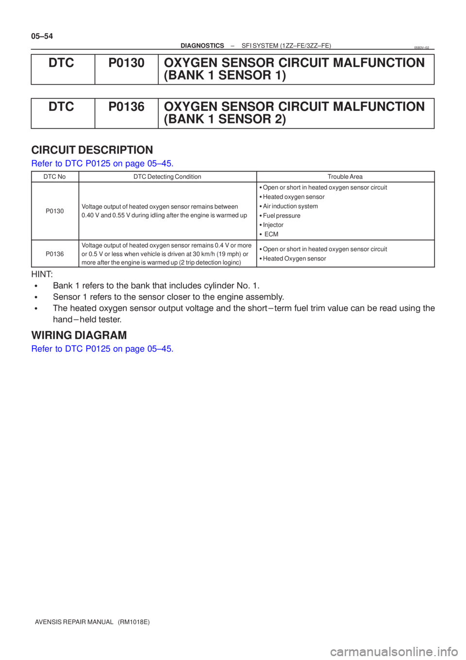
DTCP0130OXYGEN SENSOR CIRCUIT MALFUNCTION (BANK 1 SENSOR 1)
DTCP0136OXYGEN SENSOR CIRCUIT MALFUNCTION (BANK 1 SENSOR 2)
CIRCUIT DESCRIPTION
Refer to DTC P0125 on page 05±45.
DTC NoDTC Detecting ConditionTrouble Area
P0130Voltage output of heated oxygen sensor remains between
0.40 V and 0.55 V during idling after the engine is warmed up
�Open or short in heated oxygen sensor circuit
� Heated oxygen sensor
� Air induction system
� Fuel pressure
� Injector
� ECM
P0136
Voltage output of heated oxygen sensor remains 0.4 V or more
or 0.5 V or less when vehicle is driven at 30 km/h (19 mph) or
more after the engine is warmed up (2 trip detection loginc)�Open or short in heated oxygen sensor circuit
� Heated Oxygen sensor
HINT:
�� ����
�
������
���� ������\f
������\f
������
��
������
�
������
�
��������
�����
����
��
�
���
�\b�
�
�
\f����
��
�������������� �
�\f��
�������
����
������ ��
� �
�
\f�������
� �\f��
�\f�
��
��
WIRING DIAGRAM
Refer to DTC P0125 on page 05±45.
05B3V±02
Page 229 of 5135
A79067
HT1A
4
E12
Y
OX1A
23
E12
HT1B
4
E10
OX1B
21
E12
B ECM
3 EH
H17
Heated
Oxygen
Sensor
(Bank 1
Sensor 2) H7
Heated
Oxygen
Sensor
(Bank 1
Sensor 1)
B±W
21
4 E2
+B HT
OX B
P
(*1) E2
28
*1: Shielded
BR
From
Terminal 3 of
EFI Relay
(See Page 05±124)
4 4
2 1 EFI
No.2
B±W
EA1
13
B±W
B±W
IK1
10
IH2
1
B±WBR BR BR
BR
IK2
IH2
18
3 E2
+B HT
OX BR
BR
(*1)(*1)
(*1)
(*1) (*1)
(*1) P
BB
J13 J12 E
D
J13
D
J13
E
J12D
J12
D
Junction
Connector IK2
7
IH2 4
IH2
2
Engine Room
R/B No.4
E13
B±W B±W 3
2 1
4
05±46
±
DIAGNOSTICS SFI SYSTEM (1ZZ±FE/3ZZ±FE)
AVENSIS REPAIR MANUAL (RM1018E)
HINT:
� ���� ���������� �
�\f���\b�� ��� ��� ��������� ������ �� ������� ������ ������� �� ��� ������ � !"
��� ������ ��� ºDIAGNOSIS / OBD/MOBD / DATA LIST / ALLº.
WIRING DIAGRAM
Page 238 of 5135
A79108
VCECM
VTA
E2 L±W R±W
BR T2
Throttle Position Sensor
1
3
218
E13
21
E13
28
E13 VC
E2 VTA5V
E1 05±40
± DIAGNOSTICSSFI SYSTEM (1ZZ±FE/3ZZ±FE)
AVENSIS REPAIR MANUAL (RM1018E)
WIRING DIAGRAM
INSPECTION PROCEDURE
HINT:
�Read freeze frame data using ��� �� ������ �����
� Freeze frame data records the engine conditions
when a malfunction is detected. When troubleshooting, it is useful for determining whether the vehicle
was running or stopped, the engine was warmed up or not, the air±fuel ratio was lean or rich, etc. at
the time of the malfunction.
�If different DTCs that are related to a different system are output simultaneously while terminal E2 is
used as a ground terminal, terminal E2 may be open.
Page 243 of 5135

A72925
E2
Engine Coolant Temperature Sensor
2
1B±W
BR
E2 THWECM
19
E13
E13 285V
R 05±34
± DIAGNOSTICSSFI SYSTEM (1ZZ±FE/3ZZ±FE)
AVENSIS REPAIR MANUAL (RM1018E)
DTC P0115 ENGINE COOLANT TEMPERATURE CIRCUIT
CIRCUIT DESCRIPTION
A thermistor is built into the engine coolant temperature sensor and changes the resistance value according
to the engine coolant temperature.
The structure of the sensor and connection to the ECM is the same as the ones of the intake air temperature
sensor.
DTC No.DTC Detecting ConditionTrouble Area
P0115Open or short in water temp. sensor circuit
�Open or short in Engine coolant temperature sensor circuit
�Engine coolant temperature sensor
� ECM
If the ECM detects the DTC ºP0115º, it enters the fail±safe mode in which the engine coolant temperature
is assumed to be 80 �C (176 �F).
HINT:
After confirming DTC P0115, use the hand±held tester to confirm the engine coolant temperature in ºDIAG-
NOSIS / OBD/MOBD / DATA LIST / ALLº.
Temperature DisplayedMalfunction
±40 �C (±40 �F)Open circuit
140 �C (284 �F) or moreShort circuit
WIRING DIAGRAM
INSPECTION PROCEDURE
HINT:
�Read freeze frame data using ��� �� ������ �����
� Freeze frame data records the engine conditions
when a malfunction is detected. When troubleshooting, it is useful for determining whether the vehicle
was running or stopped, the engine was warmed up or not, the air±fuel ratio was lean or rich, etc. at
the time of the malfunction.
�If different DTCs that are related to a different system are output simultaneously while terminal E2 is
used as a ground terminal, terminal E2 may be open.
05B3Q±02
Page 248 of 5135

A72925
A6
Intake Air Temp. Sensor
(built in Mass Air Flow Meter)
4
5 G±R
BR E2
THA ECM
20
E13
E13 28 5V
R
THA
E2
±
DIAGNOSTICS SFI SYSTEM(1ZZ±FE/3ZZ±FE)
05±31
AVENSIS REPAIR MANUAL (RM1018E)
WIRING DIAGRAM
INSPECTION PROCEDURE
HINT:
�Read freeze frame data using \f���� ����\b�\f��\f�
� Freeze frame data records the engine conditions
when a malfunction is detected. When troubleshooting, it is useful for d\
etermining whether the vehicle
was running or stopped, the engine was warmed up or not, the air±fuel ra\
tio was lean or rich, etc. at
the time of the malfunction.
�If different DTCs that are related to a different system are output simultaneously while terminal E2 is
used as a ground terminal, terminal E2 may be open.
1READ VALUE OF HAND±HELD TESTER(INTAKE AIR TEMPERATURE)
(a)Connect the hand±held tester to the DLC3.
(b)Turn the ignition switch ON.
(c)Select the item ºDIAGNOSIS / OBD/MOBD / DATA LIST / ALL / INTAKE AIRº and read its value dis- played on the hand±held tester.
Temperature: The same as actual intake air temperature
Result:
Temperature DisplayedProceed to
±40 �C (±40 �F)A
140 �C (284 �F) or moreB
OK (Same as present temperature)C
HINT:
�If there is an open circuit, the hand±held tester indicates ±40
C (±40
F).
�If there is a short circuit, the hand±held tester indicates 140
C (284
F) or more.
BGo to step 4
CCHECK FOR INTERMITTENT PROBLEMS (See Page 05±5)
A
Page 251 of 5135

A79095
Battery FL
MAINB±Y
E12BATT
BR
E1 E9
IO1 1 EFI
7 7
3
EHECM Engine Room R/B No.1 and
Engine Room J/B No.1
2 1
1AB±Y
*1: LHD
*2: RHD IE37
*1
*2 1
Engine Room
J/B No.4 4A 1
4B 1B±G
B±G
± DIAGNOSTICSSFI SYSTEM (1ZZ±FE/3ZZ±FE)
05±119
AVENSIS REPAIR MANUAL (RM1018E)
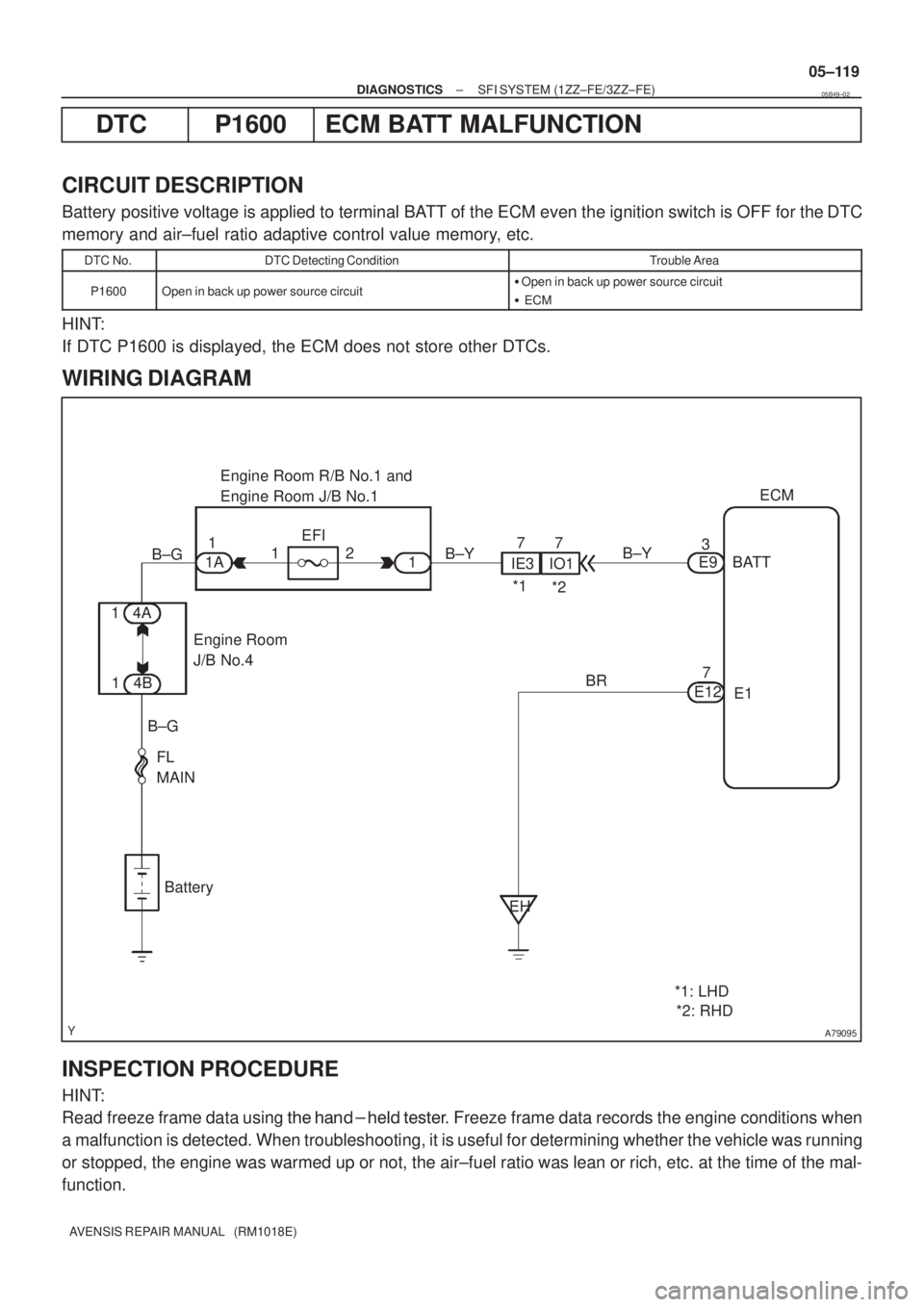
DTC P1600 ECM BATT MALFUNCTION
CIRCUIT DESCRIPTION
Battery positive voltage is applied to terminal BATT of the ECM even the ignition switch is OFF for the DTC
memory and air±fuel ratio adaptive control value memory, etc.
DTC No.DTC Detecting ConditionTrouble Area
P1600Open in back up power source circuit�Open in back up power source circuit
� ECM
HINT:
If DTC P1600 is displayed, the ECM does not store other DTCs.
WIRING DIAGRAM
INSPECTION PROCEDURE
HINT:
Read freeze frame data using ��� �� ������ �����
� Freeze frame data records the engine conditions when
a malfunction is detected. When troubleshooting, it is useful for determining whether the vehicle was running
or stopped, the engine was warmed up or not, the air±fuel ratio was lean or rich, etc. at the time of the mal-
function.
05B49±02