Page 1313 of 5135
������������������H42333
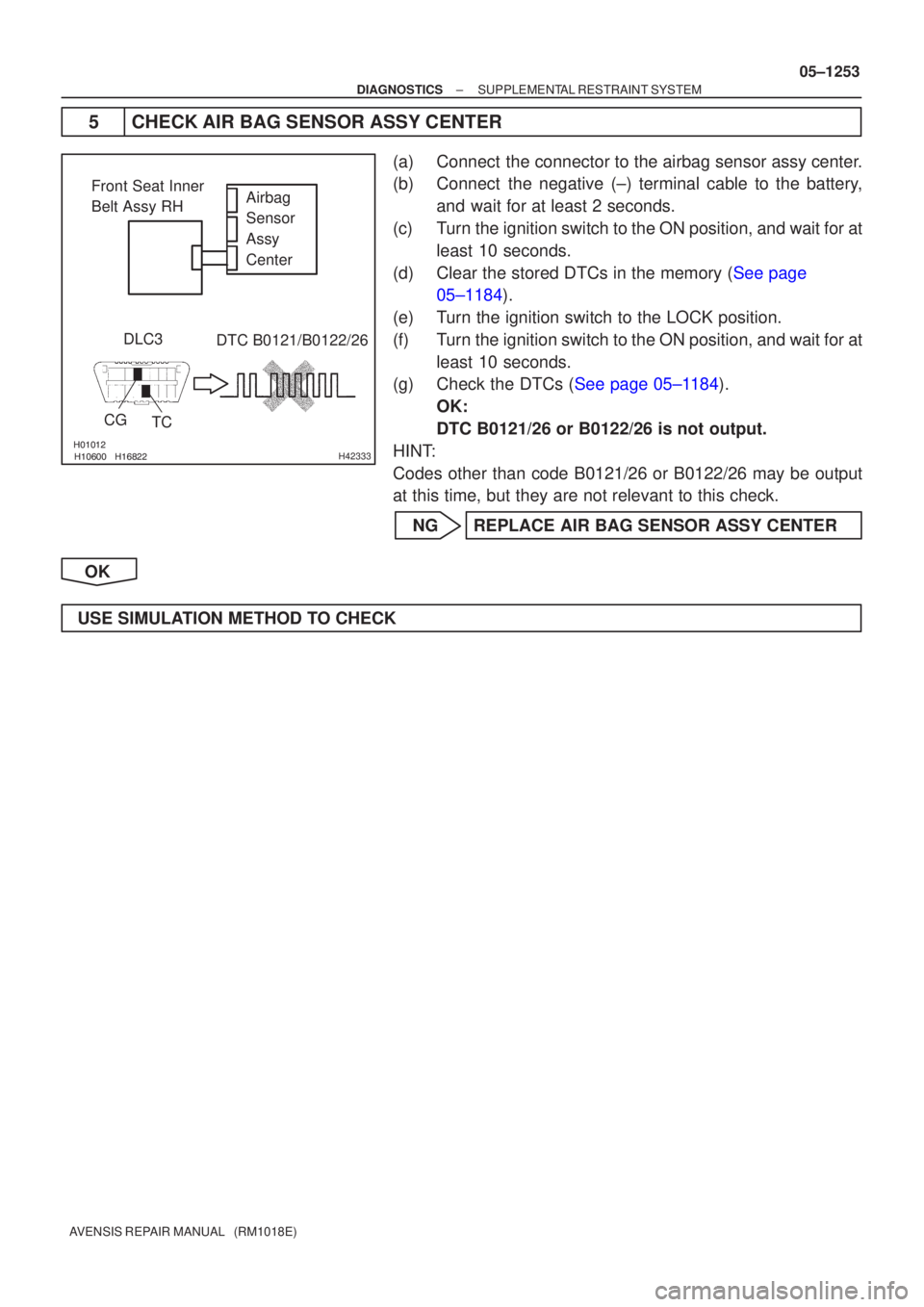
Airbag
Sensor
Assy
Center
Front Seat Inner
Belt Assy RH
DLC3
CG TC DTC B0121/B0122/26
±
DIAGNOSTICS SUPPLEMENTAL RESTRAINT SYSTEM
05±1253
AVENSIS REPAIR MANUAL (RM1018E)
5CHECK AIR BAG SENSOR ASSY CENTER
(a)Connect the connector to the airbag sensor assy center.
(b)Connect the negative (±) terminal cable to the battery,
and wait for at least 2 seconds.
(c)Turn the ignition switch to the ON position, and wait for at least 10 seconds.
(d)Clear the stored DTCs in the memory (See page 05±1184).
(e) Turn the ignition switch to the LOCK position.
(f) Turn the ignition switch to the ON position, and wait for at least 10 seconds.
(g)Check the DTCs (See page 05±1184).
OK:
DTC B0121/26 or B0122/26 is not output.
HINT:
Codes other than code B0121/26 or B0122/26 may be output
at this time, but they are not relevant to this check.
NG REPLACE AIR BAG SENSOR ASSY CENTER
OK
USE SIMULATION METHOD TO CHECK
Page 1316 of 5135

3 CHECK SEPARATE")
������
������ ������H40994
Side Squib LHDTC B0118/46
DLC3
TC
CG Airbag
Sensor
Assy
Center
C
D
±
DIAGNOSTICS SUPPLEMENTAL RESTRAINT SYSTEM
05±1249
AVENSIS REPAIR MANUAL (RM1018E)
3 CHECK SEPARATE TYPE FRONT SEAT BACK ASSY(SIDE SQUIB LH)
(a) Turn the ignition switch to the LOCK position.
(b) Disconnect the negative (±) terminal cable from the bat-
tery, and wait for at least 90 seconds.
(c) Connect the connector to the separate type front seat back assy (side squib LH).
(d) Connect the negative (±) terminal cable to the battery, and wait for at least 2 seconds.
(e) Turn the ignition switch to the ON position, and wait for at least 10 seconds.
(f)Clear the stored DTCs in the memory (See page 05±1184).
(g) Turn the ignition switch to the LOCK position.
(h) Turn the ignition switch to the ON position, and wait for at least 10 seconds.
(i)Check the DTCs (See page 05±1184). OK:
DTC B0118/46 is not output.
HINT:
Codes other than code B0118/46 may be output at this time, but
they are not related to this check.
NG REPLACE SEPARATE TYPE FRONT SEAT BACK ASSY
OK
4 USE SIMULATION METHOD TO CHECK
NG Go to step 1
OK
REPLACE ALL SRS COMPONENTS INCLUDING WIRE HARNESS
Page 1319 of 5135

3 CHECK SEPARAT")
������
������ ������H40992
TC
Side Squib LH
DTC B0117/45
DLC3
CG Airbag
Sensor
Assy
Center
C
D
05±1246
±
DIAGNOSTICS SUPPLEMENTAL RESTRAINT SYSTEM
AVENSIS REPAIR MANUAL (RM1018E)
3 CHECK SEPARATE TYPE FRONT SEAT BACK ASSY(SIDE SQUIB LH)
(a) Turn the ignition switch to the LOCK position.
(b) Disconnect the negative (±) terminal cable from the bat- tery, and wait for at least 90 seconds.
(c) Connect the connector to the separate type front seat back assy (side squib LH).
(d) Connect the negative (±) terminal cable to the battery, and wait for at least 2 seconds.
(e) Turn the ignition switch to the ON position, and wait for at least 10 seconds.
(f)Clear the stored DTCs in the memory (See page 05±1184).
(g) Turn the ignition switch to the LOCK position.
(h) Turn the ignition switch to the ON position, and wait for at least 10 seconds.
(i)Check the DTCs (See page 05±1184). OK:
DTC B0117/45 is not output.
HINT:
Codes other than code B0117/45 may be output at this time, but
they are not related to this check.
NG REPLACE SEPARATE TYPE FRONT SEAT BACK ASSY
OK
4 USE SIMULATION METHOD TO CHECK
NG Go to step 1
OK
REPLACE ALL SRS COMPONENTS INCLUDING WIRE HARNESS
Page 1322 of 5135

3 CHECK SEPARATE")
������
������ ������H40990
DLC3DTC B0116/48
TC
CG
Side Squib LH
Airbag
Sensor
Assy
Center
DC
±
DIAGNOSTICS SUPPLEMENTAL RESTRAINT SYSTEM
05±1243
AVENSIS REPAIR MANUAL (RM1018E)
3 CHECK SEPARATE TYPE FRONT SEAT BACK ASSY(SIDE SQUIB LH)
(a) Turn the ignition switch to the LOCK position.
(b) Disconnect the negative (±) terminal cable from the bat-
tery, and wait for at least 90 seconds.
(c) Connect the connector to the separate type front seat back assy (side squib LH).
(d) Connect the negative (±) terminal cable to the battery, and wait for at least 2 seconds.
(e) Turn the ignition switch to the ON position, and wait for at least 10 seconds.
(f)Clear the stored DTCs in the memory (See page 05±1184).
(g) Turn the ignition switch to the LOCK position.
(h) Turn the ignition switch to the ON position, and wait for at least 10 seconds.
(i)Check the DTCs (See page 05±1184). OK:
DTC B0116/48 is not output.
HINT:
Codes other than code B0116/48 may be output at this time, but
they are not related to this check.
NG REPLACE SEPARATE TYPE FRONT SEAT BACK ASSY
OK
USE SIMULATION METHOD TO CHECK
Page 1340 of 5135

����� �����\b�����H42526
Airbag
Sensor
Assy
Center
DLC3
Seat
Position
Airbag
Sensor
CGTC DTC B1153/25
Airbag
Sensor
Assy
Center
Seat
Position
Airbag
Sensor
LHD:
RHD:
±
DIAGNOSTICS SUPPLEMENTAL RESTRAINT SYSTEM
05±1305
AVENSIS REPAIR MANUAL (RM1018E)
INSPECTION PROCEDURE
1CHECK DTC
(a)Turn the ignition switch to the LOCK position.
(b)Disconnect the negative (±) terminal cable from the bat-
tery, and wait for at least 90 seconds.
(c)Connect the negative (±) terminal cable to the battery,
and wait for at least 2 seconds.
(d)Turn the ignition switch to the ON position, and wait for at least 10 seconds.
(e)Clear the stored DTCs in the memory (See page
05±1184).
(f) Turn the ignition switch to the LOCK position.
(g) Turn the ignition switch to the ON position, and wait for at least 10 seconds.
(h)Check the DTCs (See page 05±1184).
OK:
DTC B1153/25 is not output.
HINT:
Codes other than code B1153/25 may be output at this time, but
they are not related to this check.
NG Go to step 2
OK
USE SIMULATION METHOD TO CHECK
2 CHECK CONNECTION OF CONNECTORS
(a) Turn the ignition switch to the LOCK position.
(b) Disconnect the negative (±) terminal cable from the battery, and wait for at least 90 seconds.
(c) Check that the connectors are properly connected to the airbag sensor assy center and the seat posi- tion airbag sensor.
OK:
The connectors are connected.
NG CONNECT CONNECTORS
OK
3 CHECK VEHICLE CONDITION
(a) Check the vehicle steering position. RHD Go to step 10
LHD
Page 1342 of 5135

\f�����
� ����H42231
Airbag
Sensor
Assy
Center
LSP+ LSP±
Floor Wire
Seat Position
Airbag Sensor A
B
C
D
\f������
����\f����\bH42468
DLC3
CGTC
Airbag
Sensor
Assy
Center
Seat
Position
Airbag
Sensor
DTC B1153/25
±
DIAGNOSTICS SUPPLEMENTAL RESTRAINT SYSTEM
05±1307
AVENSIS REPAIR MANUAL (RM1018E)
6CHECK FLOOR WIRE(TO GROUND)
(a)Turn the ignition switch to the LOCK position.
(b)Disconnect the negative (±) terminal cable from the bat-
tery, and wait for at least 90 seconds.
(c)Measure the resistance between the body ground and each of LSP+ and LSP± of the connector ºBº.
OK:
Resistance: 1 M � or Higher
NGREPAIR OR REPLACE FLOOR WIRE
OK
7CHECK SEAT POSITION AIR BAG SENSOR
(a)Turn the ignition switch to the LOCK position.
(b)Disconnect the negative (±) terminal cable from the bat- tery, and wait for at least 90 seconds.
(c)Connect the connectors to the seat position airbag sensor and the airbag sensor assy center.
(d)Connect the negative (±) terminal cable to the battery, and wait for at least 2 seconds.
(e)Turn the ignition switch to the ON position, and wait for at least 10 seconds.
(f)Clear the stored DTCs in the memory (See page
05±1184).
(g) Turn the ignition switch to the LOCK position.
(h) Turn the ignition switch to the ON position, and wait for at least 10 seconds.
(i)Check the DTCs (See page 05±1184). OK:
DTC B1153/25 is not output.
HINT:
Codes other than code B1153/25 may be output at this time, but
they are not related to this check.
NG Go to step 8
OK
USE SIMULATION METHOD TO CHECK
Page 1343 of 5135

8REPLACE")
�����\b����� �����H42468
DLC3
CGTC
Airbag
Sensor
Assy
Center
Seat
Position
Airbag
Sensor
DTC B1153/25
05±1308
±
DIAGNOSTICS SUPPLEMENTAL RESTRAINT SYSTEM
AVENSIS REPAIR MANUAL (RM1018E)
8REPLACE SEAT POSITION AIRBAG SENSOR
(a)Turn the ignition switch to the LOCK position.
(b)Disconnect the negative (±) terminal cable from the battery, and wait for at least 90 seconds.
(c)Replace the seat position airbag sensor (See page 60±70).
9RECHECK DTC
(a)Connect the negative (±) terminal cable to the battery, and wait for at least 2 seconds.
(b)Turn the ignition switch to the ON position, and wait for at least 10 seconds.
(c)Clear the stored DTCs in the memory (See page
05±1184).
(d) Turn the ignition switch to the LOCK position.
(e) Turn the ignition switch to the ON position, and wait for at least 10 seconds.
(f)Check the DTCs (See page 05±1184). OK:
DTC B1153/25 is not output.
HINT:
Codes other than code B1153/25 may be output at this time, but
they are not related to this check.
NG REPLACE AIR BAG SENSOR ASSY CENTER
OK
USE SIMULATION METHOD TO CHECK
Page 1345 of 5135

H41028
Airbag
Sensor
Assy
Center
Seat Position
Airbag Sensor RSP±
RSP+Floor Wire No. 2
A
B
C
D
H42477
DLC3
CGTC DTC B1153/25
Airbag
Sensor
Assy
Center
Seat
Position
Airbag
Sensor
05±1310
±
DIAGNOSTICS SUPPLEMENTAL RESTRAINT SYSTEM
AVENSIS REPAIR MANUAL (RM1018E)
12CHECK FLOOR WIRE NO.2(TO GROUND)
(a)Turn the ignition switch to the LOCK position.
(b)Disconnect the negative (±) terminal cable from the bat- tery, and wait for at least 90 seconds.
(c)Measure the resistance between the body ground and each of RSP+ and RSP± of the connector ºBº.
OK:
Resistance: 1 M � or Higher
NGREPAIR OR REPLACE FLOOR WIRE NO.2
OK
13CHECK SEAT POSITION AIR BAG SENSOR
(a)Turn the ignition switch to the LOCK position.
(b)Disconnect the negative (±) terminal cable from the bat- tery, and wait for at least 90 seconds.
(c)Connect the connectors to the seat position airbag sensor and the airbag sensor assy center.
(d)Connect the negative (±) terminal cable to the battery, and wait for at least 2 seconds.
(e)Turn the ignition switch to the ON position, and wait for at least 10 seconds.
(f)Clear the stored DTCs in the memory (See page 05±1184).
(g) Turn the ignition switch to the LOCK position.
(h) Turn the ignition switch to the ON position, and wait for at least 10 seconds.
(i)Check the DTCs (See page 05±1184). OK:
DTC B1153/25 is not output.
HINT:
Codes other than code B1153/25 may be output at this time, but
they are not related to this check.
NG Go to step 14
OK
USE SIMULATION METHOD TO CHECK