Page 4795 of 5135

14−71
2AZ−FSE ENGINE REPAIR MANUAL (RM1083E)
(f) Mark t")
90_
Engine FrontPaint
Mark
A50671
Claw
A50672
Front Mark
Front
A52528
Front Mark
A52515
− ENGINE MECHANICALCYLINDER BLOCK ASSY (2AZ−FSE)
14−71
2AZ−FSE ENGINE REPAIR MANUAL (RM1083E)
(f) Mark the front of the bearing cap bolts with paint.
(g) Retighten the bearing cap bolts by 90_same sequence
as step (e).
(h) Check that the painted mark is now at a 90_angle to the
front.
(i) Check that the crankshaft turns smoothly.
37. INSTALL CONNECTING ROD BEARING
(a) Align the bearing claw with the groove of the connecting
rod or connecting cap.
NOTICE:
Clean the backside of the bearing and the bearing surface
of the connecting rod. The surface should be free of dust
and oil.
38. INSTALL PISTON
NOTICE:
The connecting rod cap bolts are tightened in 2 progres-
sive steps.
(a) Apply engine oil to the cylinder walls, the pistons, and the
surfaces of connecting rod bearings.
(b) Check the position of the piston ring ends.
(c) Using a piston ring compressor, push the correctly num-
bered piston and connecting rod assemblies into each
cylinder with the front mark of the piston facing forward.
NOTICE:
Match the numbered connecting rod cap with the connect-
ing rod.
(d) Check that the protrusion of the connecting rod cap is fac-
ing in the correct direction.
(e) Apply a light coat of engine oil on the threads and under
the heads of the connecting rod cap bolts.
(f) Using a 12 mm socket wrench, uniformly tighten the 2
bolts.
Torque: 25 N�m (255 kgf�cm, 18 ft�lbf)
(g) Mark the front of the connecting cap bolts with paint.
Page 5057 of 5135
(From
Februar")
A62816
2
5 3
110 8 4 796
A96569
Lot No.
A62820
Under head Length
A62816
84 2 59
7 3 1 6 10
A62823
Paint Mark
90�
Front
14–38– ENGINE MECHANICALCYLINDER HEAD GASKET (1ZZ–FE/3ZZ–FE)(From
February, 2004)
AVENSIS REPAIR MANUAL SUPPLEMENT
(RM1098E)
47. REMOVE CYLINDER HEAD SUB–ASSY
(a) Using several steps, loosen and remove the 10 cylinder
head bolts with a 10 mm hexagon wrench uniformly in the
sequence shown in the illustration. Remove the 10 cylin-
der head bolts and 10 plate washers.
(b) Remove the cylinder head.
48. REMOVE CYLINDER HEAD GASKET
49. INSTALL CYLINDER HEAD GASKET
(a) Place a new cylinder head gasket on the cylinder block
with the Lot No. stamp facing upward.
NOTICE:
�Pay attention to the mounting orientation.
�Place the cylinder head on the gasket gently in order
not to damage the gasket.
50. INSPECT CYLINDER HEAD SET BOLT
(a) Using a vernier calipers, measure the length of cylinder
head bolt from the seat to the end.
Standard length: 146.8 to 148.2 mm (5.780 to 5.835 in.)
Maximum length: 148.5 mm (5.846 in.)
If the length exceeds the maximum, replace the bolt.
51. INSTALL CYLINDER HEAD SUB–ASSY
HINT:
The cylinder head bolts are tightened in 2 successive steps.
(a) Apply a light coat of engine oil to the threads of the cylin-
der head bolts.
(b) Using several steps, install and tighten the 10 cylinder
head bolts and plate washers with a 10 mm hexagon
wrench uniformly in the sequence shown in the illustra-
tion.
Torque: 49 N⋅m (500 kgf⋅cm, 36 ft⋅lbf)
(c) Mark the front of the cylinder head bolt with paint.
(d) Retighten the cylinder head bolts by an additional 90� in
the same sequence as step (b).
(e) Check that the paint mark of each bolt is at a 90� angle
to the front.
Page 5061 of 5135
(From
February, 2004)
AVENSIS REPAIR MANUAL SUPPLEMENT
(RM1098E)
59. INS")
A62177
Raise
Push
Hook
Pin
A62178
Push
A76692
A12816
A11858
14–42– ENGINE MECHANICALCYLINDER HEAD GASKET (1ZZ–FE/3ZZ–FE)(From
February, 2004)
AVENSIS REPAIR MANUAL SUPPLEMENT
(RM1098E)
59. INSTALL CHAIN TENSIONER ASSY NO.1
(a) Check that the O–ring is clean, then set the hook as
shown in the illustration.
(b) Apply engine oil to the chain tensioner and install it with
the 2 nuts.
Torque: 9.0 N⋅m (92 kgf⋅cm, 80 in.⋅lbf)
NOTICE:
If the hook released the plunger during installation, re–
hook the plunger.
60. INSTALL CRANKSHAFT POSITION SENSOR
(a) Apply a light coat of the engine oil to the O–ring on the
crankshaft position sensor.
(b) Install the crankshaft position sensor with the 2 bolts.
Torque: 9.0 N⋅m (92 kgf⋅cm, 80 in.⋅lbf)
61. INSTALL TRANSVERSE ENGINE ENGINE MOUNTING
BRACKET
(a) Install the transverse engine engine mounting bracket
with the 3 bolts.
Torque: 47 N⋅m (479 kgf⋅cm, 35 ft⋅lbf)
62. INSTALL WATER PUMP ASSY
(See Pub. No. RM1018E on page 16–9)
63. INSTALL V–RIBBED BELT TENSIONER ASSY
(a) Install the V–ribbed belt tensioner with the nut and bolt.
Torque:
29 N⋅m (296 kgf⋅cm, 21 ft⋅lbf) for nut
69 N⋅m (704 kgf⋅cm, 51 ft⋅lbf) for bolt
Page 5109 of 5135
A95725
Plastigage
A95726
Front Mark
A95724
SST
A65715
Paint Mark90� Engine
Front
A95724
SST
– ENGINE MECHANICALCYLINDER BLOCK ASSY (1ZZ–FE/3ZZ–FE)
14–53
1ZZ–FE,3ZZ–FE ENGINE REPAIR MANUAL
(RM1099E)
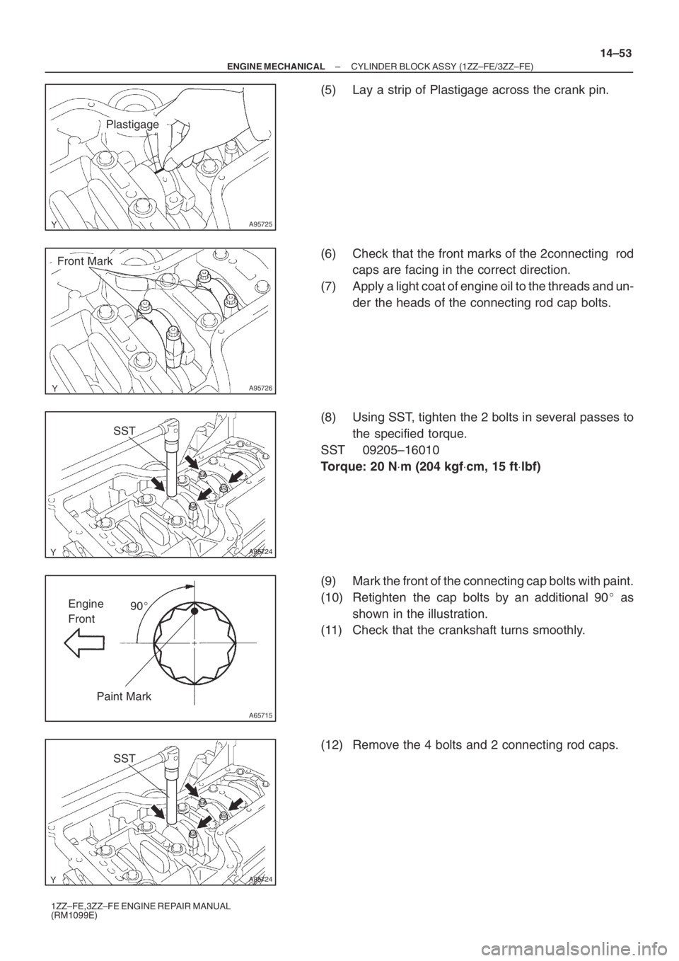
(5) Lay a strip of Plastigage across the crank pin.
(6) Check that the front marks of the 2connecting rod
caps are facing in the correct direction.
(7) Apply a light coat of engine oil to the threads and un-
der the heads of the connecting rod cap bolts.
(8) Using SST, tighten the 2 bolts in several passes to
the specified torque.
SST 09205–16010
Torque: 20 N⋅m (204 kgf⋅cm, 15 ft⋅lbf)
(9) Mark the front of the connecting cap bolts with paint.
(10) Retighten the cap bolts by an additional 90� as
shown in the illustration.
(11) Check that the crankshaft turns smoothly.
(12) Remove the 4 bolts and 2 connecting rod caps.
Page 5111 of 5135
A95721
Matchmark
A95723
SST
A01159
Plastigage
A95727
Front Mark
– ENGINE MECHANICALCYLINDER BLOCK ASSY (1ZZ–FE/3ZZ–FE)
14–55
1ZZ–FE,3ZZ–FE ENGINE REPAIR MANUAL
(RM1099E)
(d) Measure the oil clearance of the No. 1 and No. 4 cylin-
ders.
NOTICE:
Do not turn the crankshaft during the measurement.
(1) Using marking paint, write the matched cylinder
number on each connecting rod and cap.
HINT:
The matchmarks on the connecting rods and caps are for en-
suring correct reassembling.
(2) Using SST, remove the 4 bolts and 2 connecting rod
caps as shown.
SST 09205–16010
(3) Clean the crank pin and bearing.
(4) Check the crank pin and bearing for pitting and
scratches.
(5) Lay a strip of Plastigage across the crank pin.
(6) Check that the front marks of the connecting rod
cap are facing in the correct direction.
(7) Apply a light coat of engine oil to the threads and un-
der the heads of the connecting rod cap bolts.
Page 5130 of 5135

1ZZ–FE,3ZZ–FE ENGINE REPAIR MANUAL
(RM1099E)")
A64820
A01038
Seal Packing
A64968
793
481062
15
A65715
Paint Mark90� Engine
Front
14–74
– ENGINE MECHANICALCYLINDER BLOCK ASSY (1ZZ–FE/3ZZ–FE)
1ZZ–FE,3ZZ–FE ENGINE REPAIR MANUAL
(RM1099E)
32. INSTALL CRANKSHAFT
(a) Apply engine oil to the upper bearing, then install the
crankshaft onto the cylinder block.
(b) Apply a light coat of engine oil to the bolt threads, bolt
seats, and bearings of the bearing cap.
(c) Install the crankshaft onto the cylinder block.
(d) Apply a continuous bead of seal packing (Diameter; 2.5
to 3.5 mm (0.098 to 0.138 in.)) as shown in the illustration.
Seal packing: Part No. 08826–00080 or equivalent
NOTICE:
�Remove any oil from the contact surface.
�Install the bearing cap sub–assembly within 3 min-
utes after applying seal packing.
�Do not put into engine oil for at least 2 hours after
installation.
(e) Tighten the bolts in several passes in the sequence
shown to the specified torque.
Torque: 44 N⋅m (449 kgf⋅cm, 33 ft⋅lbf)
(f) Mark the front of the bearing cap bolts with paint.
(g) Retighten the bearing cap bolts by an additional 90� as
shown in the illustration.
(h) Check that the painted mark is now at a 90� angle to the
front.
Page 5132 of 5135

1ZZ–FE,3ZZ–FE")
A62813
Front Mark
Piston Ring
Compressor
A65713
Front Mark
A65714
SST
A65715
Paint Mark90� Engine
Front
A64845
14–76
– ENGINE MECHANICALCYLINDER BLOCK ASSY (1ZZ–FE/3ZZ–FE)
1ZZ–FE,3ZZ–FE ENGINE REPAIR MANUAL
(RM1099E)
(c) Using a piston ring compressor, correctly push the num-
bered piston and connecting rod assemblies into each
cylinder with the front mark of the piston facing forward.
(d) Align the pin dowels of the connecting rod cap with the
pins of the connecting rod, then install the connecting rod.
NOTICE:
Match the numbered connecting rod cap with the same
numbered connecting rod.
(e) Check that the protrusion of the connecting rod cap is fac-
ing in the correct direction.
(f) Apply a light coat of engine oil to the threads and the bot-
tom of the heads of the connecting rod cap bolts.
(g) Using SST, tighten the bolts in several passes to the spe-
cified torque.
SST 09205–16010
Torque: 20 N⋅m (204 kgf⋅cm, 15 ft⋅lbf)
(h) Mark the front of the connecting cap bolts with paint.
(i) Retighten the cap bolts by an additional 90� as shown in
the illustration.
(j) Check that the crankshaft turns smoothly.
35. INSTALL CYLINDER BLOCK WATER DRAIN COCK
SUB–ASSY
(a) Apply adhesive to 2 or 3 threads of the cylinder block wa-
ter drain cock, then install it within 3 minutes as shown in
the illustration.
Torque: 25 N⋅m (255 kgf⋅cm, 18 ft⋅lbf)
Adhesive:
Part No. 08833–00080, THREE BOND 1344, LOCTITE
242 or equivalent

14–55
1ZZ–FE,3ZZ–FE ENGINE REPAIR MANUAL
(RM1099E)
(d) Measure the oi")