Page 2756 of 5135
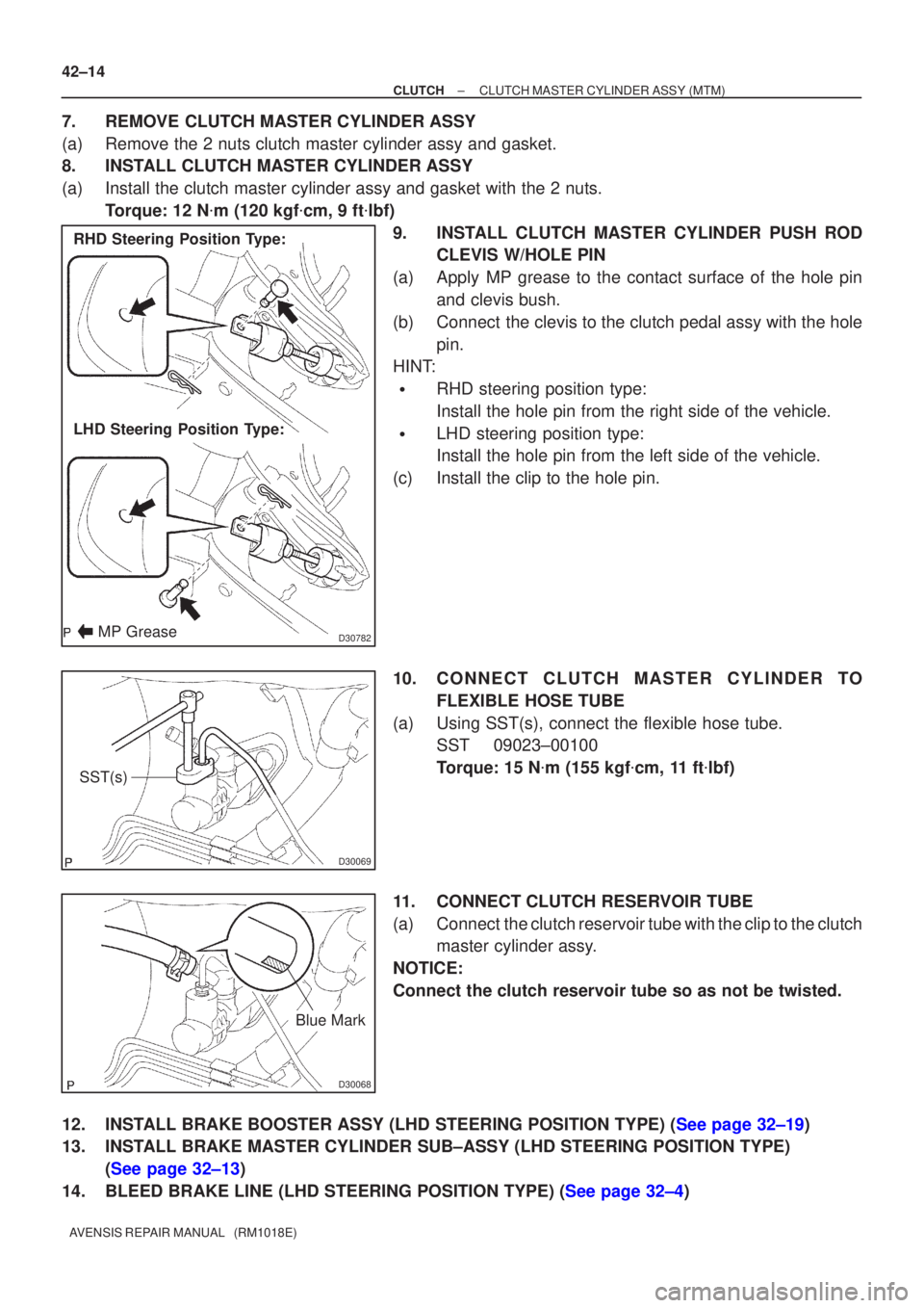
D30782
RHD Steering Position Type:
LHD Steering Position Type:
MP Grease
D30069
SST(s)
D30068
Blue Mark
42±14
±
CLUTCH CLUTCH MASTER CYLINDER ASSY (MTM)
AVENSIS REPAIR MANUAL (RM1018E)
7. REMOVE CLUTCH MASTER CYLINDER ASSY
(a) Remove the 2 nuts clutch master cylinder assy and gasket.
8. INSTALL CLUTCH MASTER CYLINDER ASSY
(a) Install the clutch master cylinder assy and gasket with the 2 nuts. Torque: 12 N �m (120 kgf �cm, 9 ft �lbf)
9. INSTALL CLUTCH MASTER CYLINDER PUSH ROD CLEVIS W/HOLE PIN
(a) Apply MP grease to the contact surface of the hole pin and clevis bush.
(b) Connect the clevis to the clutch pedal assy with the hole pin.
HINT:
�RHD steering position type:
Install the hole pin from the right side of the vehicle.
�LHD steering position type:
Install the hole pin from the left side of the vehicle.
(c) Install the clip to the hole pin.
10. CONNECT CLUTCH MASTER CYLINDER TO FLEXIBLE HOSE TUBE
(a) Using SST(s), connect the flexible hose tube. SST 09023±00100
Torque: 15 N �m (155 kgf �cm, 11 ft �lbf)
11. CONNECT CLUTCH RESERVOIR TUBE
(a) Connect the clutch reservoir tube with the clip to the clutch master cylinder assy.
NOTICE:
Connect the clutch reservoir tube so as not be twisted.
12.INSTALL BRAKE BOOSTER ASSY (LHD STEERING POSITION TYPE) (See page 32±19)
13. INSTALL BRAKE MASTER CYLINDER SUB±ASSY (LHD STEERING POSITION TYPE) (See page 32±13)
14.BLEED BRAKE LINE (LHD STEERING POSITION TYPE) (See page 32±4)
Page 3496 of 5135
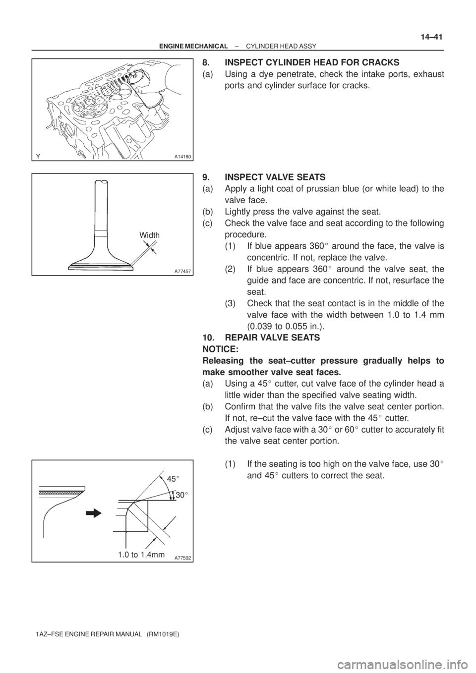
A14180
A77457
Width
A775021.0 to 1.4mm45�
30�
± ENGINE MECHANICALCYLINDER HEAD ASSY
14±41
1AZ±FSE ENGINE REPAIR MANUAL (RM1019E)
8. INSPECT CYLINDER HEAD FOR CRACKS
(a) Using a dye penetrate, check the intake ports, exhaust
ports and cylinder surface for cracks.
9. INSPECT VALVE SEATS
(a) Apply a light coat of prussian blue (or white lead) to the
valve face.
(b) Lightly press the valve against the seat.
(c) Check the valve face and seat according to the following
procedure.
(1) If blue appears 360� around the face, the valve is
concentric. If not, replace the valve.
(2) If blue appears 360� around the valve seat, the
guide and face are concentric. If not, resurface the
seat.
(3) Check that the seat contact is in the middle of the
valve face with the width between 1.0 to 1.4 mm
(0.039 to 0.055 in.).
10. REPAIR VALVE SEATS
NOTICE:
Releasing the seat±cutter pressure gradually helps to
make smoother valve seat faces.
(a) Using a 45� cutter, cut valve face of the cylinder head a
little wider than the specified valve seating width.
(b) Confirm that the valve fits the valve seat center portion.
If not, re±cut the valve face with the 45� cutter.
(c) Adjust valve face with a 30� or 60� cutter to accurately fit
the valve seat center portion.
(1) If the seating is too high on the valve face, use 30�
and 45� cutters to correct the seat.
Page 3684 of 5135
D03904
D25512
D03903
D03557
40±62
± AUTOMATIC TRANSMISSION / TRANSAUTOMATIC TRANSAXLE ASSY (U241E)
U241E A/T REPAIR MANUAL (RM840U)
Bolt length:
Bolt A: 27 mm (1.063 in.)
Bolt B: 16 mm (0.630 in.)
126. INSTALL B±3 ACCUMULATOR PISTON
(a) Coat a new O±ring with ATF, install it to the B
3 accumula-
tor piston.
(b) Coat the accumulator B
3 piston and spring with ATF,
install them to the transaxle case.
Accumulator spring:
Free length
Outer diameter mm (in.)Color
Inner 60.24 (2.3716) /
15.9 (0.626)Yellowish green
Outer 74.61 (2.9374) /
21.7 (0.854)Blue
127. INSTALL C±1 ACCUMULATOR PISTON
(a) Coat 2 new O±rings with ATF, install them to the C
1 accu-
mulator piston.
(b) Coat accumulator C
1 piston with ATF, install it to the trans-
axle case.
Accumulator spring:
Free length
Outer diameter mm (in.)Color
81.53 (3.2098) /
18.5 (0.728)Pink
Page 3715 of 5135
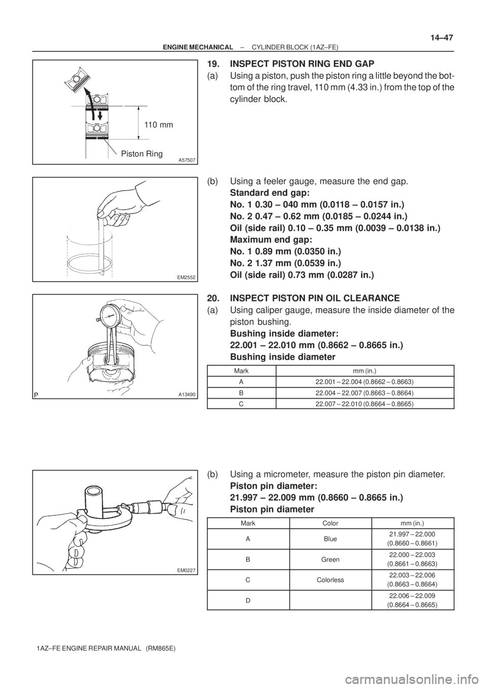
11 0 m m
A57507Piston Ring
EM2552
A13490
EM0227
± ENGINE MECHANICALCYLINDER BLOCK (1AZ±FE)
14±47
1AZ±FE ENGINE REPAIR MANUAL (RM865E)
19. INSPECT PISTON RING END GAP
(a) Using a piston, push the piston ring a little beyond the bot-
tom of the ring travel, 110 mm (4.33 in.) from the top of the
cylinder block.
(b) Using a feeler gauge, measure the end gap.
Standard end gap:
No. 1 0.30 ± 040 mm (0.0118 ± 0.0157 in.)
No. 2 0.47 ± 0.62 mm (0.0185 ± 0.0244 in.)
Oil (side rail) 0.10 ± 0.35 mm (0.0039 ± 0.0138 in.)
Maximum end gap:
No. 1 0.89 mm (0.0350 in.)
No. 2 1.37 mm (0.0539 in.)
Oil (side rail) 0.73 mm (0.0287 in.)
20. INSPECT PISTON PIN OIL CLEARANCE
(a) Using caliper gauge, measure the inside diameter of the
piston bushing.
Bushing inside diameter:
22.001 ± 22.010 mm (0.8662 ± 0.8665 in.)
Bushing inside diameter
Markmm (in.)
A22.001 ± 22.004 (0.8662 ± 0.8663)
B22.004 ± 22.007 (0.8663 ± 0.8664)
C22.007 ± 22.010 (0.8664 ± 0.8665)
(b) Using a micrometer, measure the piston pin diameter.
Piston pin diameter:
21.997 ± 22.009 mm (0.8660 ± 0.8665 in.)
Piston pin diameter
MarkColormm (in.)
ABlue21.997 ± 22.000
(0.8660 ± 0.8661)
BGreen22.000 ± 22.003
(0.8661 ± 0.8663)
CColorless22.003 ± 22.006
(0.8663 ± 0.8664)
�22.006 ± 22.009
(0.8664 ± 0.8665)
Page 3728 of 5135
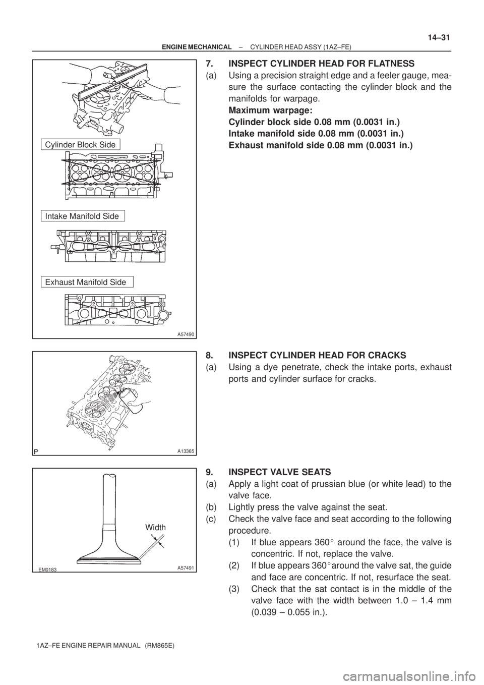
A57490
Cylinder Block Side
Intake Manifold Side
Exhaust Manifold Side
A13365
EM0183A57491
Width
± ENGINE MECHANICALCYLINDER HEAD ASSY (1AZ±FE)
14±31
1AZ±FE ENGINE REPAIR MANUAL (RM865E)
7. INSPECT CYLINDER HEAD FOR FLATNESS
(a) Using a precision straight edge and a feeler gauge, mea-
sure the surface contacting the cylinder block and the
manifolds for warpage.
Maximum warpage:
Cylinder block side 0.08 mm (0.0031 in.)
Intake manifold side 0.08 mm (0.0031 in.)
Exhaust manifold side 0.08 mm (0.0031 in.)
8. INSPECT CYLINDER HEAD FOR CRACKS
(a) Using a dye penetrate, check the intake ports, exhaust
ports and cylinder surface for cracks.
9. INSPECT VALVE SEATS
(a) Apply a light coat of prussian blue (or white lead) to the
valve face.
(b) Lightly press the valve against the seat.
(c) Check the valve face and seat according to the following
procedure.
(1) If blue appears 360� around the face, the valve is
concentric. If not, replace the valve.
(2) If blue appears 360�around the valve sat, the guide
and face are concentric. If not, resurface the seat.
(3) Check that the sat contact is in the middle of the
valve face with the width between 1.0 ± 1.4 mm
(0.039 ± 0.055 in.).
Page 3774 of 5135
EM2534
A62785
Margin
Thickness
EM2534
A62785
Margin
Thickness
A62786
Width
± ENGINE MECHANICALCYLINDER HEAD ASSY (1ZZ±FE/3ZZ±FE)
14±31
1ZZ±FE,3ZZ±FE ENGINE REPAIR MANUAL
(RM923E)
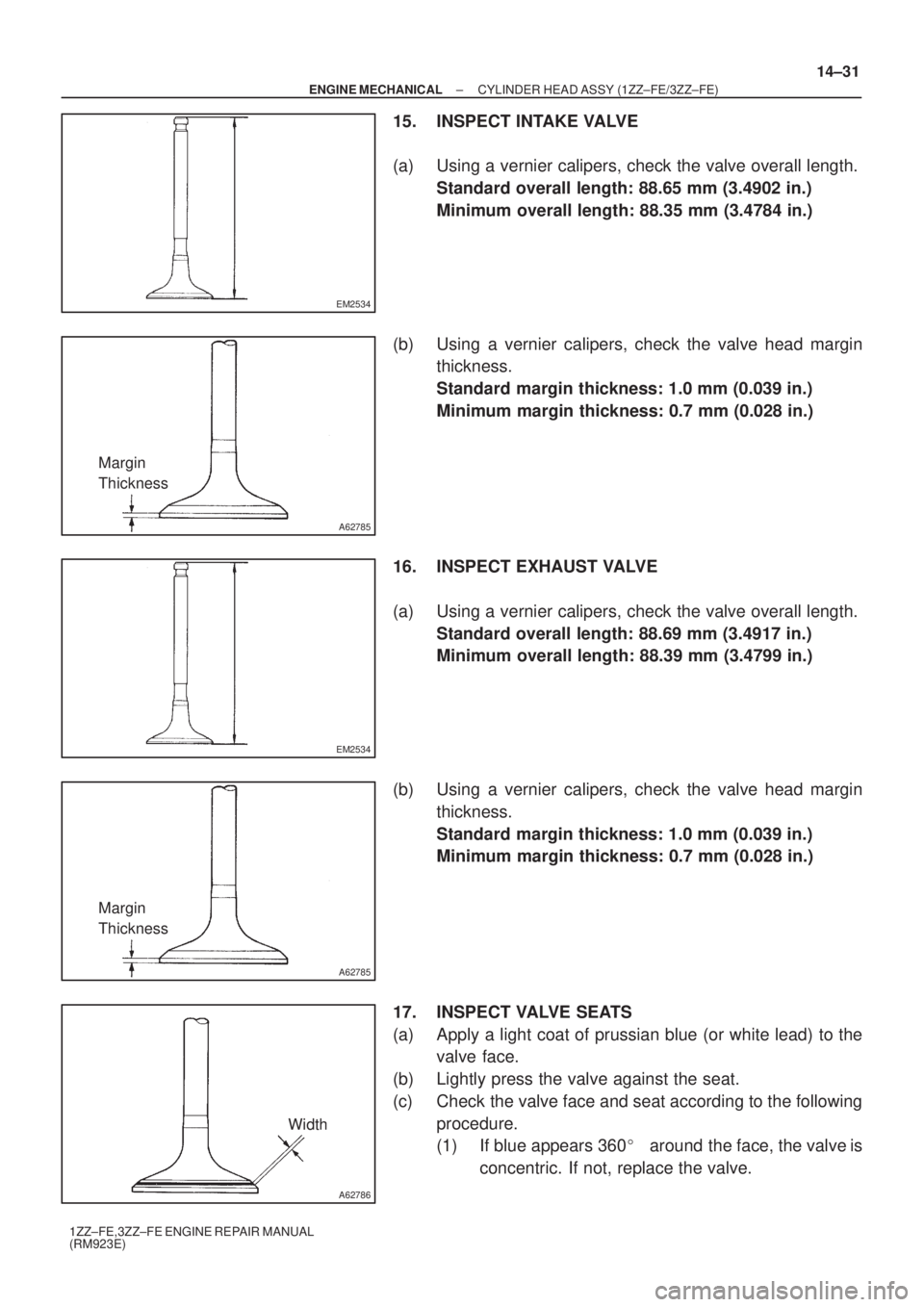
15. INSPECT INTAKE VALVE
(a) Using a vernier calipers, check the valve overall length.
Standard overall length: 88.65 mm (3.4902 in.)
Minimum overall length: 88.35 mm (3.4784 in.)
(b) Using a vernier calipers, check the valve head margin
thickness.
Standard margin thickness: 1.0 mm (0.039 in.)
Minimum margin thickness: 0.7 mm (0.028 in.)
16. INSPECT EXHAUST VALVE
(a) Using a vernier calipers, check the valve overall length.
Standard overall length: 88.69 mm (3.4917 in.)
Minimum overall length: 88.39 mm (3.4799 in.)
(b) Using a vernier calipers, check the valve head margin
thickness.
Standard margin thickness: 1.0 mm (0.039 in.)
Minimum margin thickness: 0.7 mm (0.028 in.)
17. INSPECT VALVE SEATS
(a) Apply a light coat of prussian blue (or white lead) to the
valve face.
(b) Lightly press the valve against the seat.
(c) Check the valve face and seat according to the following
procedure.
(1) If blue appears 360�around the face, the valve is
concentric. If not, replace the valve.
Page 3775 of 5135
A62787
1.0 ± 1.4 mm30� 45�
A62788
1.0 ± 1.4 mm60�
45�
P16860
A01080
14±32
± ENGINE MECHANICALCYLINDER HEAD ASSY (1ZZ±FE/3ZZ±FE)
1ZZ±FE,3ZZ±FE ENGINE REPAIR MANUAL
(RM923E)
(2) If blue appears 360� around the valve seat, the
guide and face are concentric. If not, resurface the
seat.
(3) Check that the seat contact is in the middle of the
valve face with the width between 1.0 ± 1.4 mm
(0.039 ± 0.055 in.).
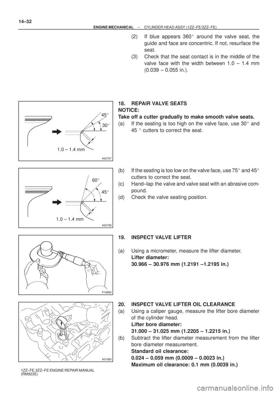
18. REPAIR VALVE SEATS
NOTICE:
Take off a cutter gradually to make smooth valve seats.
(a) If the seating is too high on the valve face, use 30� and
45 � cutters to correct the seat.
(b) If the seating is too low on the valve face, use 75� and 45�
cutters to correct the seat.
(c) Hand±lap the valve and valve seat with an abrasive com-
pound.
(d) Check the valve seating position.
19. INSPECT VALVE LIFTER
(a) Using a micrometer, measure the lifter diameter.
Lifter diameter:
30.966 ± 30.976 mm (1.2191 ±1.2195 in.)
20. INSPECT VALVE LIFTER OIL CLEARANCE
(a) Using a caliper gauge, measure the lifter bore diameter
of the cylinder head.
Lifter bore diameter:
31.000 ± 31.025 mm (1.2205 ± 1.2215 in.)
(b) Subtract the lifter diameter measurement from the lifter
bore diameter measurement.
Standard oil clearance:
0.024 ± 0.059 mm (0.0009 ± 0.0023 in.)
Maximum oil clearance: 0.1 mm (0.0039 in.)
Page 3834 of 5135
A56676
A56677
SST
A56678
Sharp 6 mm
Reamer
± ENGINE MECHANICALCYLINDER HEAD ASSY (1CD±FTV)
14±29
1CD±FTV ENGINE REPAIR MANUAL (RM927E)
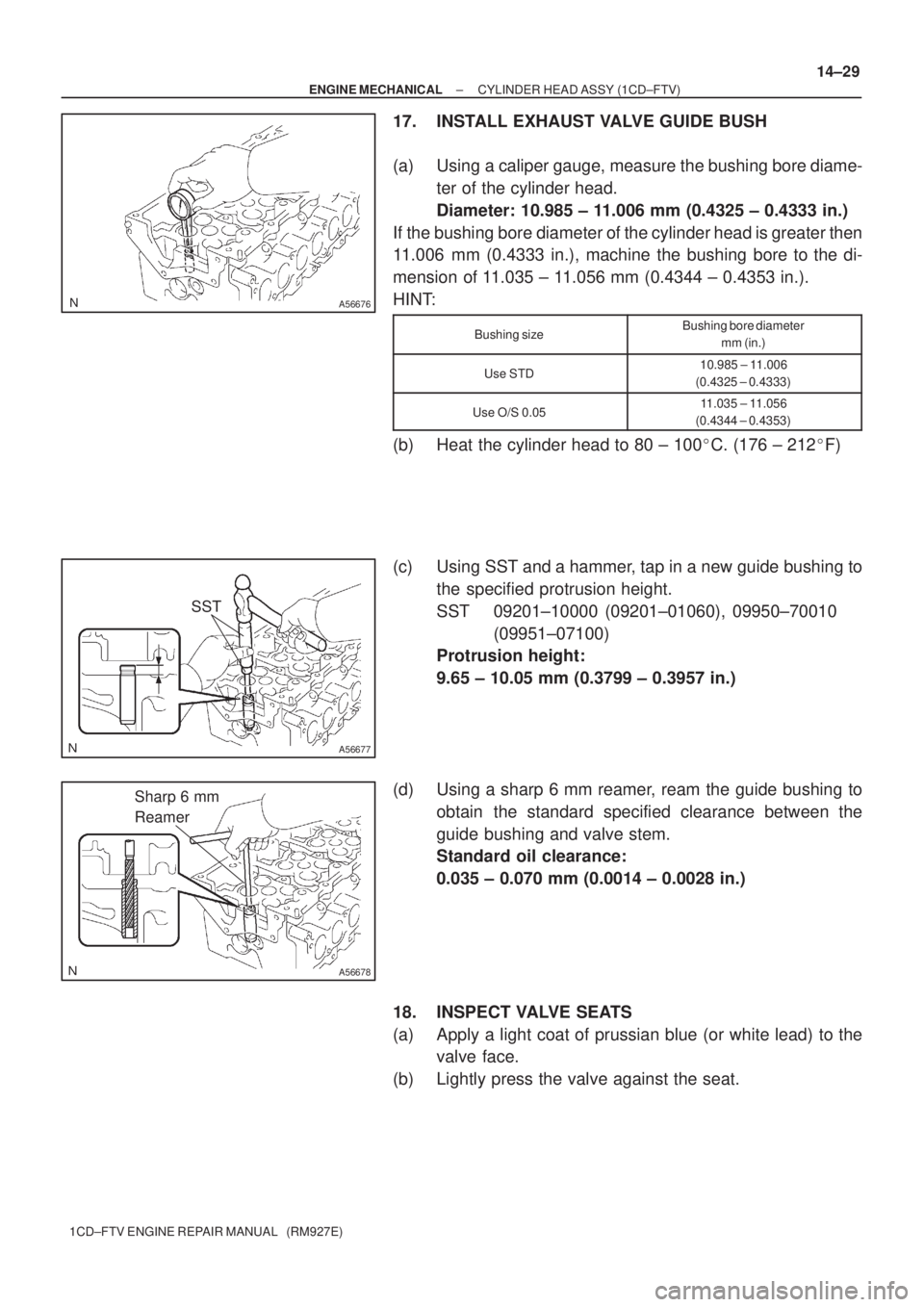
17. INSTALL EXHAUST VALVE GUIDE BUSH
(a) Using a caliper gauge, measure the bushing bore diame-
ter of the cylinder head.
Diameter: 10.985 ± 11.006 mm (0.4325 ± 0.4333 in.)
If the bushing bore diameter of the cylinder head is greater then
11.006 mm (0.4333 in.), machine the bushing bore to the di-
mension of 11.035 ± 11.056 mm (0.4344 ± 0.4353 in.).
HINT:
Bushing sizeBushing bore diameter
mm (in.)
Use STD10.985 ± 11.006
(0.4325 ± 0.4333)
Use O/S 0.0511.035 ± 11.056
(0.4344 ± 0.4353)
(b) Heat the cylinder head to 80 ± 100�C. (176 ± 212�F)
(c) Using SST and a hammer, tap in a new guide bushing to
the specified protrusion height.
SST 09201±10000 (09201±01060), 09950±70010
(09951±07100)
Protrusion height:
9.65 ± 10.05 mm (0.3799 ± 0.3957 in.)
(d) Using a sharp 6 mm reamer, ream the guide bushing to
obtain the standard specified clearance between the
guide bushing and valve stem.
Standard oil clearance:
0.035 ± 0.070 mm (0.0014 ± 0.0028 in.)
18. INSPECT VALVE SEATS
(a) Apply a light coat of prussian blue (or white lead) to the
valve face.
(b) Lightly press the valve against the seat.