Page 3835 of 5135

A56053
Width
45�25�
Z03988
45�
70�
A57105Contacting Width
A09537
14±30
± ENGINE MECHANICALCYLINDER HEAD ASSY (1CD±FTV)
1CD±FTV ENGINE REPAIR MANUAL (RM927E)
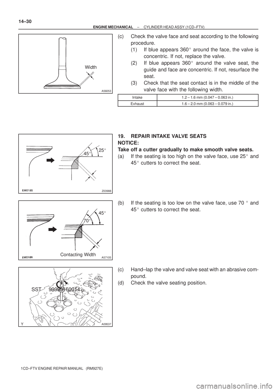
(c) Check the valve face and seat according to the following
procedure.
(1) If blue appears 360� around the face, the valve is
concentric. If not, replace the valve.
(2) If blue appears 360� around the valve seat, the
guide and face are concentric. If not, resurface the
seat.
(3) Check that the seat contact is in the middle of the
valve face with the following width.
Intake1.2 ± 1.6 mm (0.047 ± 0.063 in.)
Exhaust1.6 ± 2.0 mm (0.063 ± 0.079 in.)
19. REPAIR INTAKE VALVE SEATS
NOTICE:
Take off a cutter gradually to make smooth valve seats.
(a) If the seating is too high on the valve face, use 25� and
45� cutters to correct the seat.
(b) If the seating is too low on the valve face, use 70 � and
45� cutters to correct the seat.
(c) Hand±lap the valve and valve seat with an abrasive com-
pound.
(d) Check the valve seating position.
SST 99999±60014
Page 4746 of 5135

190V6−01
Z11580A80938A82936
Type A:
Type B:
BlueWhite
Red Green DarkClear or
light yellow
B00543
B00540
19−6
− STARTING & CHARGINGCHARGING SYSTEM (2AZ−FSE)
AVENSIS Supplement (RM1045E)
ON−VEHICLE INSPECTION
1. INSPECT BATTERY (EXCEPT MAINTENANCE−FREE
BATTERY)
(a) Check the battery electrolyte level.
(1) Check the electrolyte quantity of each cell.
If the electrolyte quantity is below the recommended amount,
add distilled water.
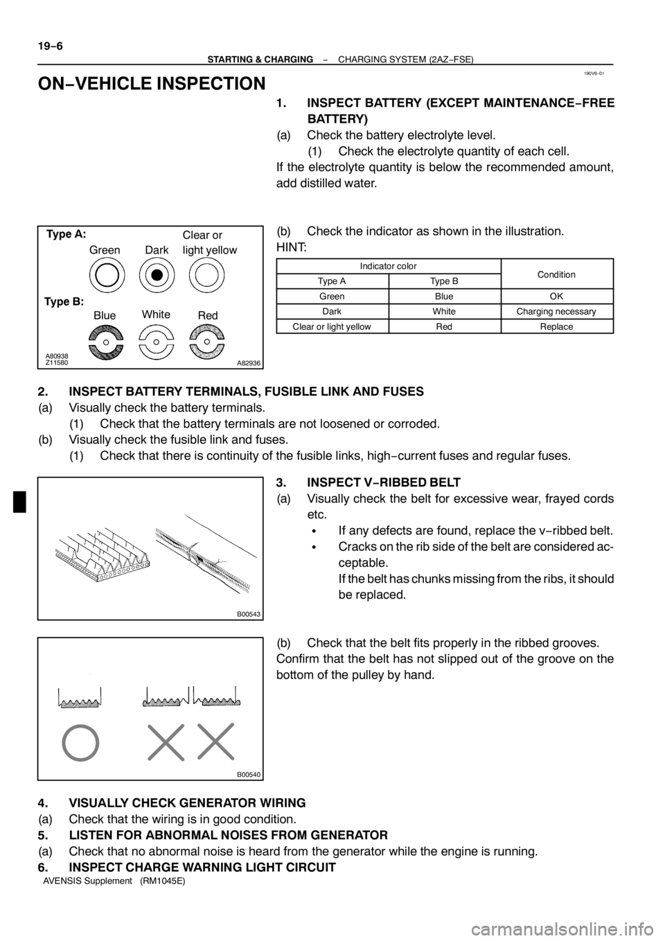
(b) Check the indicator as shown in the illustration.
HINT:
Indicator colorConditionType AType BCondition
GreenBlueOK
DarkWhiteCharging necessary
Clear or light yellowRedReplace
2. INSPECT BATTERY TERMINALS, FUSIBLE LINK AND FUSES
(a) Visually check the battery terminals.
(1) Check that the battery terminals are not loosened or corroded.
(b) Visually check the fusible link and fuses.
(1) Check that there is continuity of the fusible links, high−current fuses and regular fuses.
3. INSPECT V−RIBBED BELT
(a) Visually check the belt for excessive wear, frayed cords
etc.
SIf any defects are found, replace the v−ribbed belt.
SCracks on the rib side of the belt are considered ac-
ceptable.
If the belt has chunks missing from the ribs, it should
be replaced.
(b) Check that the belt fits properly in the ribbed grooves.
Confirm that the belt has not slipped out of the groove on the
bottom of the pulley by hand.
4. VISUALLY CHECK GENERATOR WIRING
(a) Check that the wiring is in good condition.
5. LISTEN FOR ABNORMAL NOISES FROM GENERATOR
(a) Check that no abnormal noise is heard from the generator while the engine is running.
6. INSPECT CHARGE WARNING LIGHT CIRCUIT
Page 4892 of 5135

D26710
Thrust Needle
Roller BearingMultiple Disc
Clutch Clutch
Hub
D26711
Thrust Needle
Roller BearingMultiple Disc
Clutch Clutch
Hub
D03820
Thrust Needle
Roller Bearing
D03574
Forward Clutch Assy
40−62
− AUTOMATIC TRANSMISSION / TRANSAUTOMATIC TRANSAXLE ASSY (U151E/U151F)
U151E, U151F A/T REPAIR MANUAL (RM1021U)
(b) Coat the thrust needle roller bearing and race with yellow
petrolatum, install them onto the multiple disc clutch hub.
Thrust bearing and race diameter: mm (in.)
InsideOutside
Thrust Bearing36.4 (1.433)52.2 (2.055)
(c) Coat the needle roller bearing with ATF.
(d) Install the needle roller bearing to the multiple clutch hub.
Bearing diameter: mm (in.)
InsideOutside
Bearing23.6 (0.929)44 (1.732)
(e) Install the multiple clutch hub to the transaxle case.
125. INSTALL FORWARD CLUTCH ASSY
(a) Coat the thrust needle roller bearing with ATF.
(b) Install the thrust needle roller bearing to the forward
clutch.
Thrust bearing diameter: mm (in.)
InsideOutside
Thrust Bearing33.58 (1.3220)51.9 (2.043)
NOTICE:
Install the thrust bearing properly so that the no colored
race or blue ink jet race will be visible.
(c) Install the forward clutch to the forward clutch assy.
NOTICE:
SAlign the splines of all discs in the forward clutch with
those of multiple clutch hub to assemble them se-
curely.
SBe careful not to damage the bush inside of the for-
ward clutch hub during installing.
Page:
< prev 1-8 9-16 17-24