Page 1506 of 5135

± DIAGNOSTICSNAVIGATION SYSTEM
05±1455
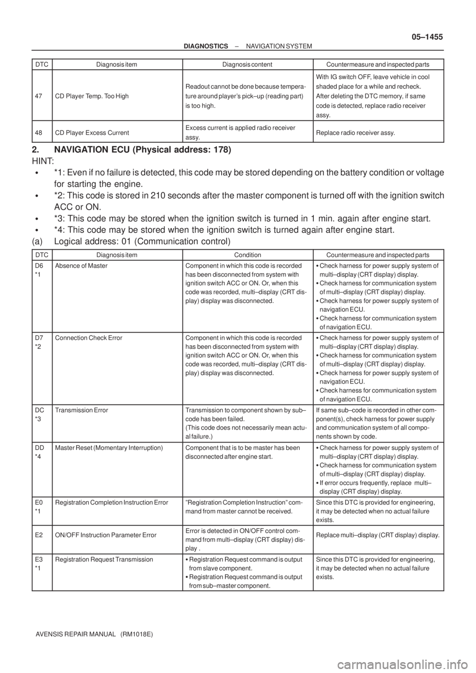
AVENSIS REPAIR MANUAL (RM1018E) DTCCountermeasure and inspected parts Diagnosis content Diagnosis item
47CD Player Temp. Too High
Readout cannot be done because tempera-
ture around player's pick±up (reading part)
is too high.
With IG switch OFF, leave vehicle in cool
shaded place for a while and recheck.
After deleting the DTC memory, if same
code is detected, replace radio receiver
assy.
48CD Player Excess CurrentExcess current is applied radio receiver
assy.Replace radio receiver assy.
2. NAVIGATION ECU (Physical address: 178)
HINT:
�*1: Even if no failure is detected, this code may be stored depending on the battery condition or voltage
for starting the engine.
�*2: This code is stored in 210 seconds after the master component is turned off with the ignition switch
ACC or ON.
�*3: This code may be stored when the ignition switch is turned in 1 min. again after engine start.
�*4: This code may be stored when the ignition switch is turned again after engine start.
(a) Logical address: 01 (Communication control)
DTCDiagnosis itemConditionCountermeasure and inspected parts
D6
*1Absence of MasterComponent in which this code is recorded
has been disconnected from system with
ignition switch ACC or ON. Or, when this
code was recorded, multi±display (CRT dis-
play) display was disconnected.�Check harness for power supply system of
multi±display (CRT display) display.
�Check harness for communication system
of multi±display (CRT display) display.
�Check harness for power supply system of
navigation ECU.
�Check harness for communication system
of navigation ECU.
D7
*2Connection Check ErrorComponent in which this code is recorded
has been disconnected from system with
ignition switch ACC or ON. Or, when this
code was recorded, multi±display (CRT dis-
play) display was disconnected.�Check harness for power supply system of
multi±display (CRT display) display.
�Check harness for communication system
of multi±display (CRT display) display.
�Check harness for power supply system of
navigation ECU.
�Check harness for communication system
of navigation ECU.
DC
*3Transmission ErrorTransmission to component shown by sub±
code has been failed.
(This code does not necessarily mean actu-
al failure.)If same sub±code is recorded in other com-
ponent(s), check harness for power supply
and communication system of all compo-
nents shown by code.
DD
*4Master Reset (Momentary Interruption)Component that is to be master has been
disconnected after engine start.�Check harness for power supply system of
multi±display (CRT display) display.
�Check harness for communication system
of multi±display (CRT display) display.
�If error occurs frequently, replace multi±
display (CRT display) display.
E0
*1Registration Completion Instruction ErrorºRegistration Completion Instructionº com-
mand from master cannot be received.Since this DTC is provided for engineering,
it may be detected when no actual failure
exists.
E2ON/OFF Instruction Parameter ErrorError is detected in ON/OFF control com-
mand from multi±display (CRT display) dis-
play .Replace multi±display (CRT display) display.
E3
*1Registration Request Transmission�Registration Request command is output
from slave component.
�Registration Request command is output
from sub±master component.Since this DTC is provided for engineering,
it may be detected when no actual failure
exists.
Page 1551 of 5135
05±1484
±
DIAGNOSTICS NAVIGATION SYSTEM
AVENSIS REPAIR MANUAL (RM1018E)
MAP IS DISPLAYED IN WHITE OR BLUE SCREEN (SWITCHED AND VEHICLE POSITION MARK ARE DISPLAYED)
INSPECTION PROCEDURE
1CHECK SETTING
(a)Check the settings.
(1)Check that the map display is normal when the map scale is set to the wi\
destarea.
Standard: Map display is normal
OKSYSTEM OK
NG
2CHECK AND OPERATE AGAIN
(a)Clean the map disc. (1)After wiping the map disc in the circumference direction with a soft clo\
th, insert it again.
OKSYSTEM OK
NG
3REPLACE DISC PLAYER DISC
Standard: Normally returns OKSYSTEM OK
NG
REPLACE NAVIGATION ECU (See page 67±27)
05C3P±01
Page 1552 of 5135

±
DIAGNOSTICS NAVIGATION SYSTEM
05±1483
AVENSIS REPAIR MANUAL (RM1018E)
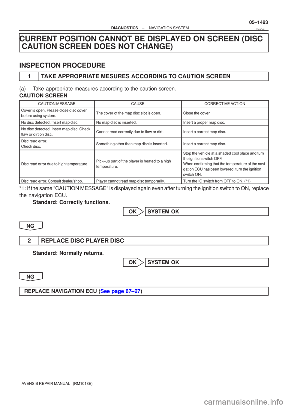
CURRENT POSITION CANNOT BE DISPLAYED ON SCREEN (DISC
CAUTION SCREEN DOES NOT CHANGE)
INSPECTION PROCEDURE
1TAKE APPROPRIATE MESURES ACCORDING TO CAUTION SCREEN
(a)Take appropriate measures according to the caution screen.
CAUTION SCREEN
CAUTION MESSAGECAUSECORRECTIVE ACTION
Cover is open. Please close disc cover
before using system.The cover of the map disc slot is open.Close the cover.
No disc detected. Insert map disc.No map disc is inserted.Insert a proper map disc.
No disc detected. Insert map disc. Check
flaw or dirt on disc.Cannot read correctly due to flaw or dirt.Insert a correct map disc.
Disc read error.
Check disc.Something other than map disc is inserted.Insert a correct map disc.
Disc read error due to high temperature.Pick±up part of the player is heated to a high
temperature.
Stop the vehicle at a shaded cool place and turn
the ignition switch OFF.
When confirming that the temperature of the navi-
gation ECU has been lowered, turn the ignition
switch ON.
Disc read error. Consult dealer/shop.Player cannot read map disc temporarily.Turn the IG switch from OFF to ON. (*1)
*1: If the same ºCAUTION MESSAGEº is displayed again even after turni\
ng the ignition switch to ON, replace
the navigation ECU.
Standard: Correctly functions.
OKSYSTEM OK
NG
2REPLACE DISC PLAYER DISC
Standard: Normally returns. OKSYSTEM OK
NG
REPLACE NAVIGATION ECU (See page 67±27)
05C3O±01
Page 3130 of 5135
I35224
Front No.2 Speaker AssyAmplifier Antenna Assy
Front No.1 Speaker
Assy
Rear Speaker AssyNavigation System:
Disc Player Bracket No.2 Rivet
Navigation ECUPower Point Socket Cover
Power Point Socket Assy
Liftback:
Antenna Cord Sub±assy No.3Amplifier Antenna Assy Wagon:
Non±reusable part ��
Disc Player Bracket No.3
Rivet �
Rear No.2 Speaker Assy
Navigation ECU Cover
± AUDIO & VISUAL SYSTEMAUDIO & VISUAL SYSTEM
67±3
AVENSIS REPAIR MANUAL (RM1018E)
Page 4003 of 5135
670SH±02
I35209
I35210
I35211
±
AUDIO & VISUAL SYSTE MNAVIG ATION ECU
67±27
A VENSIS RE PAIR MANUAL (RM1018E)
N AVIG ATION ECU
REPLACEMENT
1. DISCONNEC T B ATTE RY NEG ATIVE TERMINAL ( See page 60±1)
2 . REMOVE FRONT SE AT ASSY LH ( See page POWER SE AT 72± 11 , MANUAL SE AT 72±16 )
3 . REMOVE N AVIG ATION ECU COVER
(a ) Remove the navigation ECU cover (Front side).
(b ) Remove the 3 clips and the navigation ECU cove r.
4 . REMOVE N AVIG ATION COMPUTER W/BRACKET
(a ) Remove the 2 bolts.
(b ) Disconnec t the connectors and remove the navigation
compute r w/ bracket.
5 . REMOVE DISC PL AYER BRACKET NO.2
(a ) Remove the 2 screws and disc player bracket No.2.
6 . REMOVE DISC PL AYER BRACKET NO.3
(a ) Remove the 2 screws and disc player bracket No.3.
7 . REMOVE N AVIG ATION ECU
8 . INSTALL FRONT SE AT ASSY LH ( See page POWER SE AT 72± 11 , MANUAL SE AT 72±16 )