Page 1930 of 5135
110TB±01
A79569
A79570
SST
A79571
A79572
11±52
±
FUEL FUEL PUMP ASSY(1AZ±FSE)
AVENSIS REPAIR MANUAL (RM1018E)
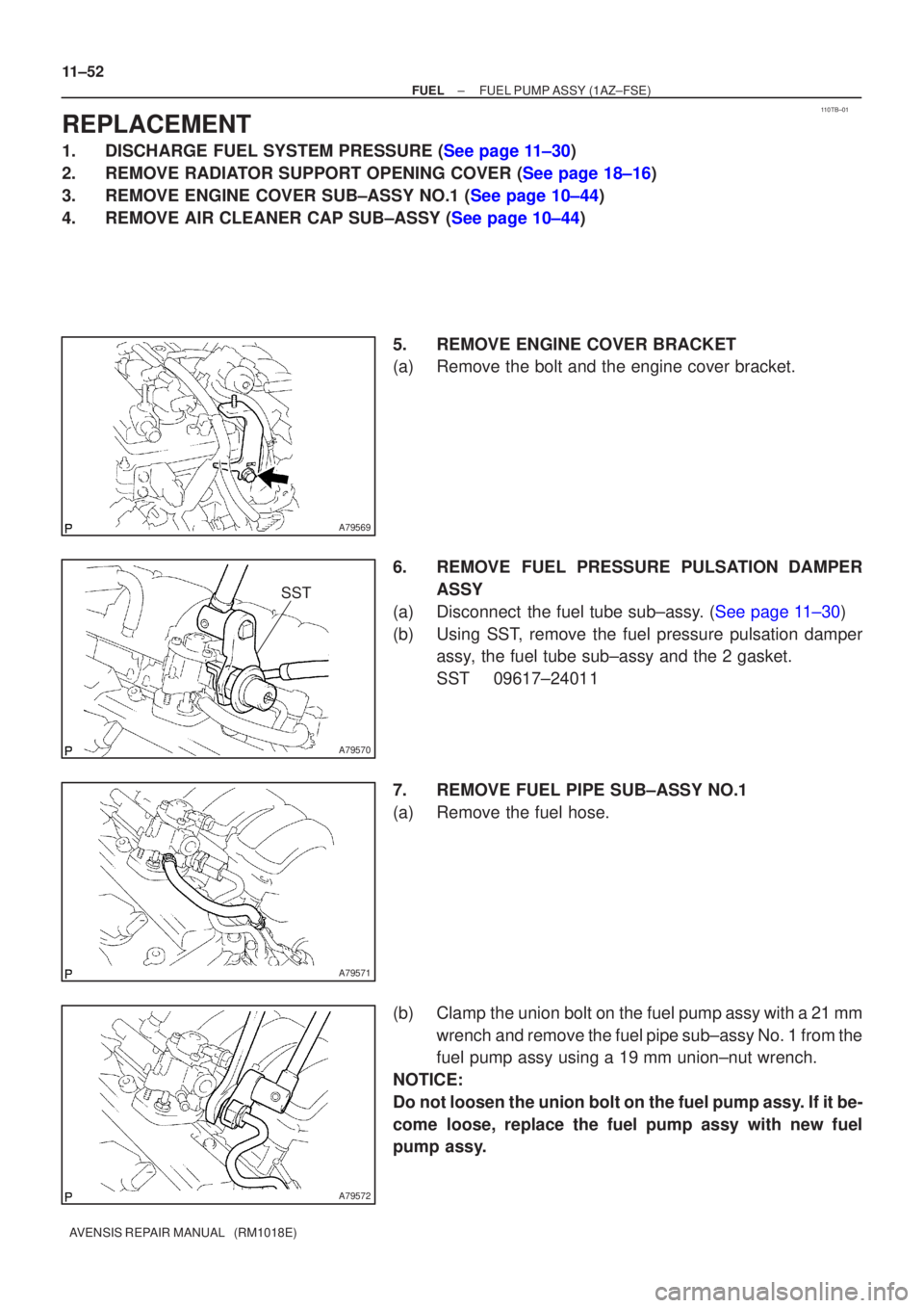
REPLACEMENT
1.DISCHARGE FUEL SYSTEM PRESSURE (See page 11±30)
2.REMOVE RADIATOR SUPPORT OPENING COVER (See page 18±16)
3.REMOVE ENGINE COVER SUB±ASSY NO.1 (See page 10±44)
4.REMOVE AIR CLEANER CAP SUB±ASSY (See page 10±44) 5.REMOVE ENGINE COVER BRACKET
(a)Remove the bolt and the engine cover bracket.
6.REMOVE FUEL PRESSURE PULSATION DAMPERASSY
(a)Disconnect the fuel tube sub±assy. (See page 11±30)
(b) Using SST, remove the fuel pressure pulsation damper assy, the fuel tube sub±assy and the 2 gasket.
SST 09617±24011
7. REMOVE FUEL PIPE SUB±ASSY NO.1
(a) Remove the fuel hose.
(b) Clamp the union bolt on the fuel pump assy with a 21 mm wrench and remove the fuel pipe sub±assy No. 1 from the
fuel pump assy using a 19 mm union±nut wrench.
NOTICE:
Do not loosen the union bolt on the fuel pump assy. If it be-
come loose, replace the fuel pump assy with new fuel
pump assy.
Page 1932 of 5135
A79575
Fuel Injector
Back±up Ring No. 1
Fuel Injector
Back±up Ring No. 2
O±ring
Fuel injector
Back±up Ring No. 3
A79576
A79570
SST
11±54
± FUELFUEL PUMP ASSY (1AZ±FSE)
AVENSIS REPAIR MANUAL (RM1018E)
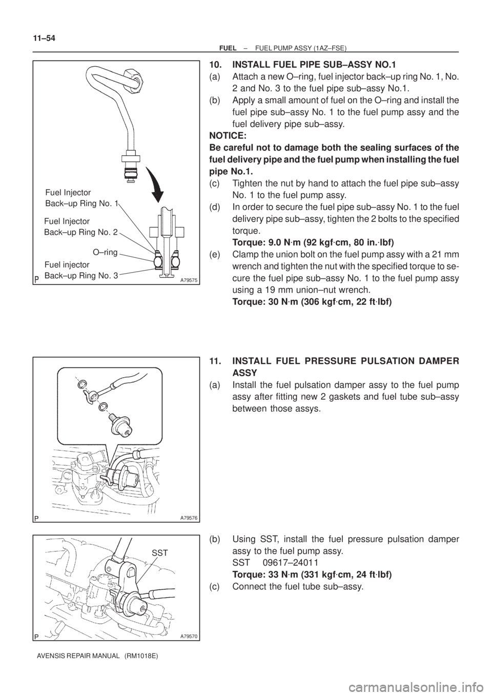
10. INSTALL FUEL PIPE SUB±ASSY NO.1
(a) Attach a new O±ring, fuel injector back±up ring No. 1, No.
2 and No. 3 to the fuel pipe sub±assy No.1.
(b) Apply a small amount of fuel on the O±ring and install the
fuel pipe sub±assy No. 1 to the fuel pump assy and the
fuel delivery pipe sub±assy.
NOTICE:
Be careful not to damage both the sealing surfaces of the
fuel delivery pipe and the fuel pump when installing the fuel
pipe No.1.
(c) Tighten the nut by hand to attach the fuel pipe sub±assy
No. 1 to the fuel pump assy.
(d) In order to secure the fuel pipe sub±assy No. 1 to the fuel
delivery pipe sub±assy, tighten the 2 bolts to the specified
torque.
Torque: 9.0 N�m (92 kgf�cm, 80 in.�lbf)
(e) Clamp the union bolt on the fuel pump assy with a 21 mm
wrench and tighten the nut with the specified torque to se-
cure the fuel pipe sub±assy No. 1 to the fuel pump assy
using a 19 mm union±nut wrench.
Torque: 30 N�m (306 kgf�cm, 22 ft�lbf)
11. INSTALL FUEL PRESSURE PULSATION DAMPER
ASSY
(a) Install the fuel pulsation damper assy to the fuel pump
assy after fitting new 2 gaskets and fuel tube sub±assy
between those assys.
(b) Using SST, install the fuel pressure pulsation damper
assy to the fuel pump assy.
SST 09617±24011
Torque: 33 N�m (331 kgf�cm, 24 ft�lbf)
(c) Connect the fuel tube sub±assy.
Page 1960 of 5135
110U5±01
A78493
A80060
w/o HID Sensor:
w/ HID Sensor:
(c)
(d)
(c)
±
FUEL FUEL TANK ASSY(GASOLINE)
11±93
AVENSIS REPAIR MANUAL (RM1018E)
Removal & Installation and Disassembly & Reassembly
1.DISCHARGE FUEL SYSTEM PRESSURE
HINT:
�1ZZ±FE/3ZZ±FE: 11±1
�1AZ±FE: 11±15
�1AZ±FSE: 11±30
2.REMOVE REAR SEAT CUSHION ASSY (SEAT FIXED TYPE) (See page 72±32)
3.REMOVE COVER, RR FLOOR SERVICE HOLE (See page 11±85)
4.DISCONNECT FUEL TANK RETURN TUBE (1AZ±FSE ENGINE TYPE)
(See page 11±85)
5.DISCONNECT FUEL TANK MAIN TUBE SUB±ASSY (See page 11±85)
6.DISCONNECT FUEL EVAPORATION TUBE SUB±ASSY NO.2 (See page 11±85)
7.REMOVE FUEL SUCTION W/PUMP & GAGE TUBE ASSY (See page 11±85)
SST 09808±14010
8. DRAIN FUEL
9. REMOVE FRONT FLOOR FOOTREST (W/O HID SENSOR)
10.REMOVE FLOOR PANEL BRACE FRONT (See page 15±2)
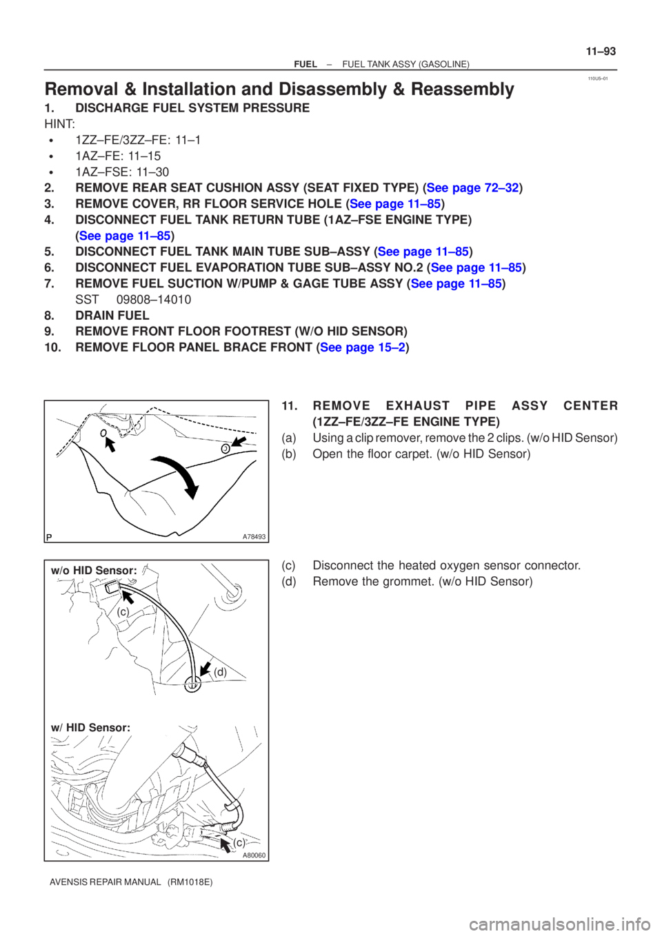
11. REMOVE EXHAUST PIPE ASSY CENTER(1ZZ±FE/3ZZ±FE ENGINE TYPE)
(a) Using a clip remover, remove the 2 clips. (w/o HID Sensor)
(b) Open the floor carpet. (w/o HID Sensor)
(c) Disconnect the heated oxygen sensor connector.
(d) Remove the grommet. (w/o HID Sensor)
Page 2043 of 5135
141CG±01
A784575 Claws
A78458
A78505
A78515
±
ENGINE MECHANICAL PARTIAL ENGINE ASSY (1ZZ±FE/3ZZ±FE)
14±27
AVENSIS REPAIR MANUAL (RM1018E)
REPLACEMENT
1.DISCHARGE FUEL SYSTEM PRESSURE (See page 11±1)
2. REMOVE RADIATOR SUPPORT OPENING COVER
(a) Remove the retainer and the 4 clips.
(b) Unfasten the 5 claws, and remove the radiator supportopening cover.
3. REMOVE ENGINE ROOM COVER SIDE
(a) Remove the 2 clips and the engine room cover side.
4. REMOVE FRONT WHEELS
5. REMOVE ENGINE UNDER COVER SUB±ASSY NO.1
(a) Remove the 5 clips, 2 screws, bolt and detach the engine under cover.
6. REMOVE ENGINE UNDER COVER LH
(a) Remove the 6 screws and 5 clips, then detach the engine under cover.
Page 2067 of 5135
A76706
Fuel Delivery Pipe Sub±assy
No. 1 Spacer
Ignition Coil Assy
V±Ribbed Belt Tensioner Assy
� Gasket
Intake Manifold
Clamp Bracket
Oil Level Gage Guide
� O±ring
Oil Level Gage
Sub±assy
Crankshaft Position
Sensor� Gasket Thermostat Knock Sensor
Engine Oil Pressure
Switch AssyCamshaft Position Sensor� Gasket Water By±pass Pipe No. 1
� Non±reusable part
N´m (kgf´cm, ft´lbf) : Specified torque
Water Inlet
19 (194, 14)
9.0 (92, 80 in.�lbf)
9.0 (92, 80 in.�lbf)
9.0 (92, 80 in.�lbf)
9.0 (92, 80 in.�lbf)29 (296, 21)
69 (704, 51)
15 (153, 11)
20 (204, 15)
11 (112, 8)
30 (306, 22)
9.0 (92, 80 in.�lbf)
Transverse Engine
Engine Mounting Bracket
13 (133, 10)
47 (479, 35)
± ENGINE MECHANICALPARTIAL ENGINE ASSY (1ZZ±FE/3ZZ±FE)
14±25
AVENSIS REPAIR MANUAL (RM1018E)
Page 2069 of 5135
141BF±01
A77281
A77301
±
ENGINE MECHANICAL PARTIAL ENGINE ASSY(1AZ±FE)
14±121
AVENSIS REPAIR MANUAL (RM1018E)
REPLACEMENT
1.DISCHARGE FUEL SYSTEM PRESSURE (See page 11±19)
2.REMOVE FRONT WHEELS
3.REMOVE RADIATOR SUPPORT OPENING COVER
4.REMOVE ENGINE ROOM COVER SIDE
5.REMOVE ENGINE UNDER COVER RH
6.REMOVE ENGINE UNDER COVER LH
7.DRAIN COOLANT (See page 16±19)
8.DRAIN ENGINE OIL
(a)Install a new gasket and the drain plug after draining engine oil.
Torque: 25 N �m (255 kgf �cm,18 ft �lbf)
9.DRAIN MANUAL TRANSAXLE OIL (M/T TRANSAXLE) Torque: 49 N �m (500 kgf �cm,36 ft �lbf)
10.DRAIN AUTOMATIC TRANSAXLE FLUID (A/T TRANSAXLE) (See page 40±2)
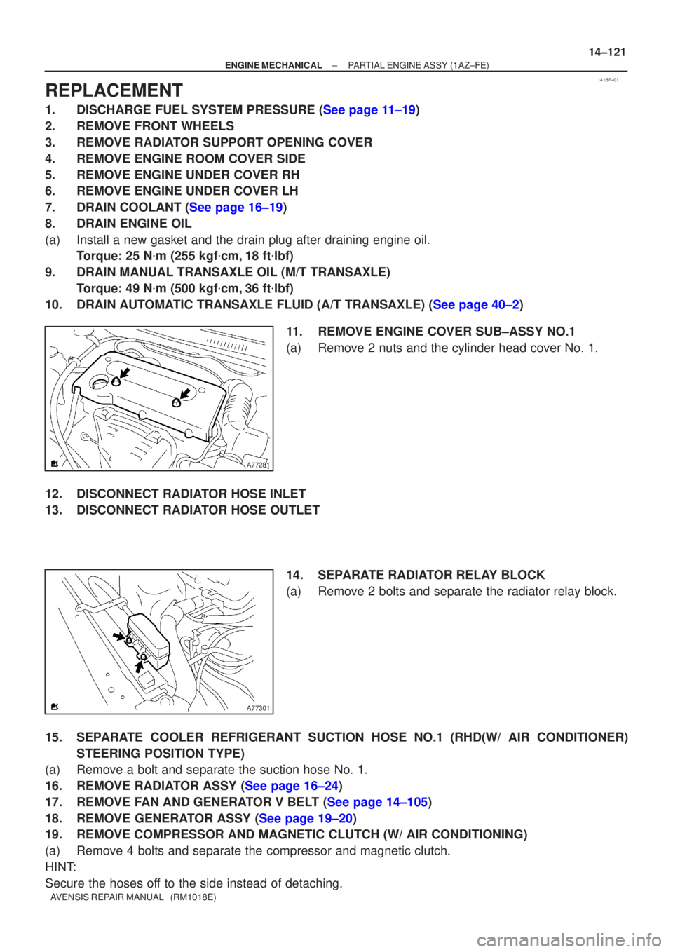
11.REMOVE ENGINE COVER SUB±ASSY NO.1
(a)Remove 2 nuts and the cylinder head cover No. 1.
12.DISCONNECT RADIATOR HOSE INLET
13.DISCONNECT RADIATOR HOSE OUTLET 14.SEPARATE RADIATOR RELAY BLOCK
(a)Remove 2 bolts and separate the radiator relay block.
15.SEPARATE COOLER REFRIGERANT SUCTION HOSE NO.1 (RHD(W/ AIR CONDITIONER) STEERING POSITION TYPE)
(a)Remove a bolt and separate the suction hose No. 1.
16.REMOVE RADIATOR ASSY (See page 16±24)
17.REMOVE FAN AND GENERATOR V BELT (See page 14±105)
18.REMOVE GENERATOR ASSY (See page 19±20)
19. REMOVE COMPRESSOR AND MAGNETIC CLUTCH (W/ AIR CONDITIONING)
(a) Remove 4 bolts and separate the compressor and magnetic clutch.
HINT:
Secure the hoses off to the side instead of detaching.
Page 2076 of 5135
A60067
A52497
A32676
A78645
Oil Pressure Switch
14±128
±
ENGINE MECHANICAL PARTIAL ENGINE ASSY(1AZ±FE)
AVENSIS REPAIR MANUAL (RM1018E)
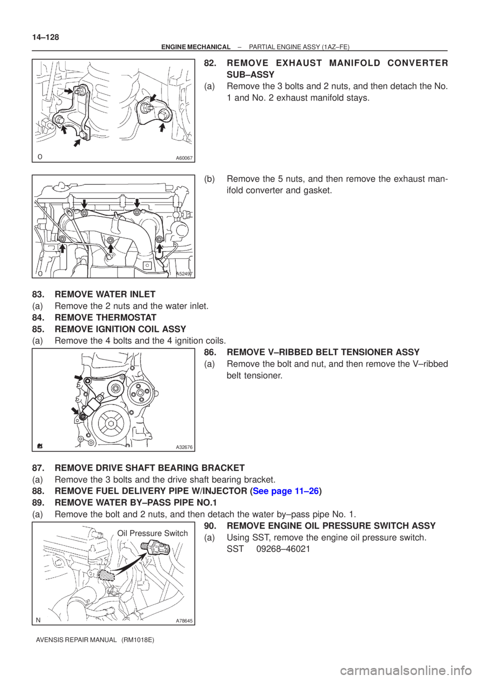
82.REMOVE EXHAUST MANIFOLD CONVERTER SUB±ASSY
(a)Remove the 3 bolts and 2 nuts, and then detach the No.
1 and No. 2 exhaust manifold stays.
(b)Remove the 5 nuts, and then remove the exhaust man- ifold converter and gasket.
83.REMOVE WATER INLET
(a)Remove the 2 nuts and the water inlet.
84.REMOVE THERMOSTAT
85.REMOVE IGNITION COIL ASSY
(a)Remove the 4 bolts and the 4 ignition coils. 86.REMOVE V±RIBBED BELT TENSIONER ASSY
(a)Remove the bolt and nut, and then remove the V±ribbedbelt tensioner.
87.REMOVE DRIVE SHAFT BEARING BRACKET
(a)Remove the 3 bolts and the drive shaft bearing bracket.
88.REMOVE FUEL DELIVERY PIPE W/INJECTOR (See page 11±26)
89. REMOVE WATER BY±PASS PIPE NO.1
(a) Remove the bolt and 2 nuts, and then detach the water by±pass pipe No\
. 1. 90. REMOVE ENGINE OIL PRESSURE SWITCH ASSY
(a) Using SST, remove the engine oil pressure switch.SST 09268±46021
Page 2077 of 5135
A77332
23
145
±
ENGINE MECHANICAL PARTIAL ENGINE ASSY(1AZ±FE)
14±129
AVENSIS REPAIR MANUAL (RM1018E)
91.REMOVE KNOCK SENSOR
(a)Remove the nut and the knock sensor.
92.REMOVE ENGINE COOLANT TEMPERATURE SENSOR
(a)Using SST, remove the engine coolant temperature sensor.
SST09817±33190
93.REPLACE PARTIAL ENGINE ASSY
94.INSTALL ENGINE COOLANT TEMPERATURE SENSOR
(a)Install a new gasket to the engine coolant temperature sensor.
(b)Install the engine coolant temperature sensor. Torque: 20 N �m (208 kgf �cm,15 ft �lbf)
SST09817±33190
95.INSTALL KNOCK SENSOR
Torque: 20 N �m (208 kgf �cm,15 ft �lbf)
96.INSTALL ENGINE OIL PRESSURE SWITCH ASSY
(a)Clean the threads of the oil pressure switch, apply adhesive there. Adhesive: Part No. 08833±00080 THREE BOND 1344 or equivalent
(b)Install the oil pressure switch. Torque: 15 N �m (153 kgf �cm,11 ft �lbf)
97.INSTALL WATER BY±PASS PIPE NO.1
(a)Install a new gasket and the water by±pass pipe No. 1 with the bolt a\
nd 2 nuts. Torque: 9.0 N �m (92 kgf �cm,80 in. �lbf)
98.INSTALL FUEL DELIVERY PIPE W/INJECTOR (See page 11±26)
99.INSTALL DRIVE SHAFT BEARING BRACKET Torque: 54 N �m (551 kgf �cm,40 ft �lbf)
100.INSTALL V±RIBBED BELT TENSIONER ASSY
Torque: 60 N �m (607 kgf �cm,44 ft �lbf)
101.INSTALL IGNITION COIL ASSY Torque: 9.0 N �m (92 kgf �cm,80 in. �lbf)
102.INSTALL THERMOSTAT (See page 16±23)
103. INSTALL WATER INLET
Torque: 9.0 N �m (92 kgf �cm, 80 in. �lbf)
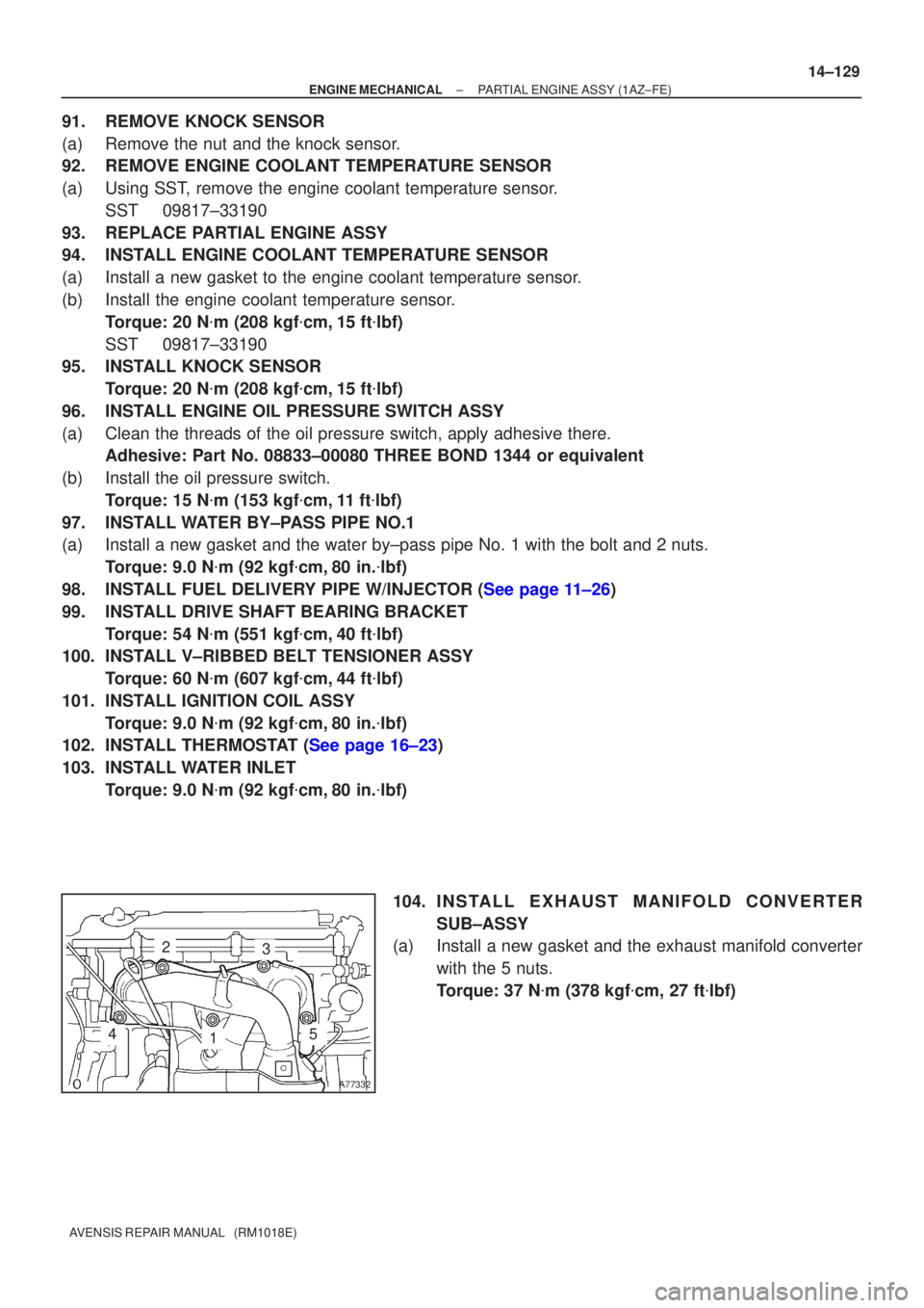
104. I N S TA L L E X HAUST MANIFOLD CONVERTER
SUB±ASSY
(a) Install a new gasket and the exhaust manifold converter
with the 5 nuts.
Torque: 37 N �m (378 kgf �cm, 27 ft �lbf)