Page 760 of 5135
05±666
± DIAGNOSTICSECD SYSTEM (1CD±FTV)
AVENSIS REPAIR MANUAL (RM1018E)
P1272:
Required sensorsFuel pressure sensor
Frequency of operationOnce per driving cycle
Duration1 sec.
CHK ENG operation2 driving cycles
TYPICAL ENABLING CONDITIONS
P1271:
Specification
Drive the vehicle at 50 km/h with the 3 rd transmission gear and then decelerate it by completly releasing the accelerator pedal
P1272:
ItemSpecificationItemMinimumMaximum
Fuel pressure30 MPa (306 kgf/cm2, 4,351 psi)±
Fuel temperature0�C±
Battery voltage11 V±
The monitor will not run if the fuel pressure sensor, or pressure discharge valve circuit, or fuel temp. sensor is malfunctioning
TYPICAL MALFUNCTION THRESHOLDS
P1271:
Threshold
If the confirmation signals from the EDU is not present, despite the ECM sending the command signals regularly during decelerating
P1272:
Threshold
If the internal pressure stays beyond the specified level after the ignition switch was turned OFF
Page 766 of 5135

05±672
±
DIAGNOSTICS ECD SYSTEM(1CD±FTV)
AVENSIS REPAIR MANUAL (RM1018E)
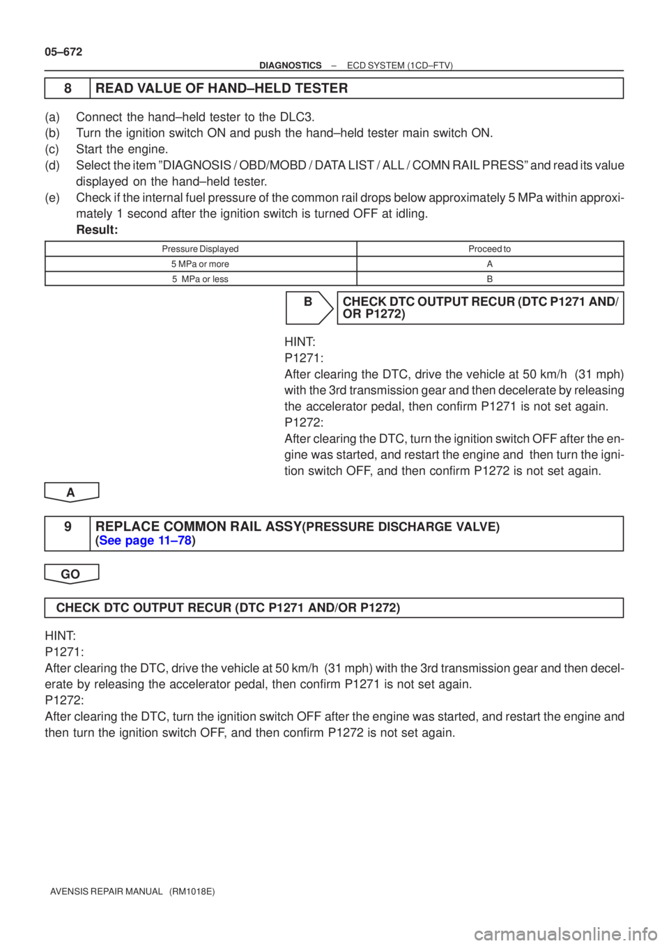
8READ VALUE OF HAND±HELD TESTER
(a)Connect the hand±held tester to the DLC3.
(b)Turn the ignition switch ON and push the hand±held tester main switch \
ON.
(c)Start the engine.
(d)Select the item ºDIAGNOSIS / OBD/MOBD / DATA LIST / ALL / COMN RAIL PRESSº and read its value displayed on the hand±held tester.
(e)Check if the internal fuel pressure of the common rail drops below approximat\
ely 5 MPa within approxi- mately 1 second after the ignition switch is turned OFF at idling.
Result:
Pressure DisplayedProceed to
5 MPa or moreA
5 MPa or lessB
BCHECK DTC OUTPUT RECUR (DTC P1271 AND/ OR P1272)
HINT:
P1271:
After clearing the DTC, drive the vehicle at 50 km/h (31 mph)
with the 3rd transmission gear and then decelerate by releasing
the accelerator pedal, then confirm P1271 is not set again.
P1272:
After clearing the DTC, turn the ignition switch OFF after the en-
gine was started, and restart the engine and then turn the igni-
tion switch OFF, and then confirm P1272 is not set again.
A
9REPLACE COMMON RAIL ASSY(PRESSURE DISCHARGE VALVE)
(See page 11±78)
GO
CHECK DTC OUTPUT RECUR (DTC P1271 AND/OR P1272)
HINT:
P1271:
After clearing the DTC, drive the vehicle at 50 km/h (31 mph) with the 3rd\
transmission gear and then decel-
erate by releasing the accelerator pedal, then confirm P1271 is not set again\
.
P1272:
After clearing the DTC, turn the ignition switch OFF after the engine was sta\
rted, and restart the engine and
then turn the ignition switch OFF, and then confirm P1272 is not set again.
Page 1246 of 5135
I36139
F17
05±1178
± DIAGNOSTICSCOMBUSTION TYPE POWER HEATER SYSTEM
AVENSIS REPAIR MANUAL (RM1018E)
4 INSPECT POWER HEATER FUEL PUMP
(a) Connect the positive (+) lead from the battery to terminal
1 and negative (±) to terminal 2 with the power heater
turned on and check the pressure of the hose by hand.
Standard: The pressure is applied to the hose.
NG REPAIR OR REPLACE POWER HEATER FUEL
PUMP
OK
PROCEED TO NEXT CIRCUIT INSPECTION SHOWN IN PROBLEM SYMPTOMS TABLE
Page 1535 of 5135
Terminal No.
Wire harness side
Turn Signal Flasher Relay
Skid Control ECU with Actuator Brake Fluid Level Warning Switch
Engine ECU
Oil Pressure Switch
DOME Fuse Headlight Beam Level Control ECU
Skid Control ECU with Actuator
Skid Control ECU with Actuator Turn Signal Flasher Relay Engine ECU ± Multi Display RAD No.1 Fuse
GND
EMPS ECU
TAIL Fuse
Skid Control ECU with Actuator Fuel Sensor Gauge
Skid Control ECU with Actuator
± GND
Rear Fog Light Relay Front Fog Light Relay Multi Display Fuse Filter Warning Switch (*1)
IGN Fuse Fuel Sender Gauge
Engine Oil Level Sensor Security ECU Ambient Temp. Sensor
4P OUT (Other Parts) H±HI RH Fuse/H±LP RH Fuse 1
2
3
4
5
6
7
8
9
10
11
12
13
14
15
16
17
18
19
201
2
3
4
5
6
7
8
9
10
11
12
13
14
15
16
17
18
C10
Airbag Sensor Assembly GND
GAUGE1 Fuse Skid Control ECU with Actuator
C11Engine ECU
Integration Relay
21
22
*1: 1CD±FTVAmbient Temp. Sensor
± DIAGNOSTICSCOMBINATION METER
05±1505
AVENSIS REPAIR MANUAL (RM1018E)
Page 1815 of 5135

100FA±01
A79596
A78436
10�
10 � Upper
Engine
Front
10±52
±
ENGINE CONTROL SYSTEM KNOCK SENSOR(1AZ±FSE)
AVENSIS REPAIR MANUAL (RM1018E)
REPLACEMENT
1.DISCHARGE FUEL SYSTEM PRESSURE (See page 11±30)
2.REMOVE RADIATOR SUPPORT OPENING COVER (See page 18±16)
3.REMOVE ENGINE ROOM COVER SIDE (See page 18±17)
4.REMOVE ENGINE COVER SUB±ASSY NO.1 (See page 10±44)
5.DRAIN ENGINE COOLANT (See page 16±31)
6.REMOVE AIR CLEANER CAP SUB±ASSY (See page 10±44)
7.REMOVE THROTTLE BODY ASSY (See page 10±44)
8.REMOVE CHARCOAL CANISTER ASSY
9.REMOVE ENGINE COVER BRACKET (See page 11±52)
10.REMOVE FUEL PUMP ASSY (See page 11±52)
11.REMOVE INTAKE MANIFOLD (See page 11±42)
12.REMOVE SURGE TANK STAY NO.1 (See page 11±42)
13.REMOVE INTAKE MANIFOLD INSULATOR NO.2 (See page 11±42) 14.REMOVE KNOCK SENSOR
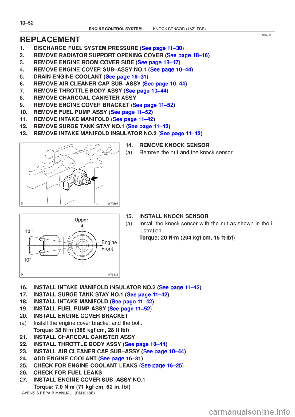
(a)Remove the nut and the knock sensor.
15.INSTALL KNOCK SENSOR
(a)Install the knock sensor with the nut as shown in the il-lustration.
Torque: 20 N �m (204 kgf �cm, 15 ft �lbf)
16.INSTALL INTAKE MANIFOLD INSULATOR NO.2 (See page 11±42)
17.INSTALL SURGE TANK STAY NO.1 (See page 11±42)
18.INSTALL INTAKE MANIFOLD (See page 11±42)
19.INSTALL FUEL PUMP ASSY (See page 11±52)
20. INSTALL ENGINE COVER BRACKET
(a) Install the engine cover bracket and the bolt. Torque: 38 N �m (388 kgf �cm, 28 ft �lbf)
21. INSTALL CHARCOAL CANISTER ASSY
22.INSTALL THROTTLE BODY ASSY (See page 10±44)
23.INSTALL AIR CLEANER CAP SUB±ASSY (See page 10±44)
24.ADD ENGINE COOLANT (See page 16±31)
25.CHECK FOR ENGINE COOLANT LEAKS (See page 16±25)
26. CHECK FOR FUEL LEAKS
27. INSTALL ENGINE COVER SUB±ASSY NO.1
Torque: 7.0 N �m (71 kgf �cm, 62 in. �lbf)
Page 1819 of 5135
A79577
N´m (kgf´cm, ft´lbf)
: Specified torque
� Non±reusable part� Gasket� GasketFuel Tube Sub±assy
Fuel Pipe Clamp
Fuel Pressure Pulsation
Damper Assy Fuel Pump Assy
� Fuel Pump
Insulator
Fuel HoseFuel pipe Sub±assy No. 1
� Fuel Injector Back±up Ring No. 1
25 (255, 18)
33 (331, 24)
9.0 (92, 80 in.�lbf)
38 (388, 28)
30 (306, 22)
� Fuel Injector Back±up Ring No. 2
� Fuel Injector Back±up Ring No. 3 � O±ring
Engine Cover Bracket
± ENGINE CONTROL SYSTEMKNOCK SENSOR (1AZ±FSE)
10±49
AVENSIS REPAIR MANUAL (RM1018E)
Page 1832 of 5135

100FL±01
A77917
A77918
(a)
(b)
A77919
10±34
±
ENGINE CONTROL SYSTEM KNOCK SENSOR(1AZ±FE)
AVENSIS REPAIR MANUAL (RM1018E)
REPLACEMENT
1.DISCHARGE FUEL SYSTEM PRESSURE (See page 11±15)
2.REMOVE ENGINE ROOM COVER SIDE (See page 10±26)
3.REMOVE RADIATOR SUPPORT OPENING COVER (See page 10±26)
4.ENGINE COOLANT (See page 16±19)
5.REMOVE ENGINE COVER SUB±ASSY NO.1 (See page 10±26)
6.REMOVE AIR CLEANER CAP SUB±ASSY (See page 10±26)
7.SEPARATE ACCELERATOR CONTROL CABLE ASSY (See page 10±26)
8.REMOVE THROTTLE BODY ASSY (See page 10±26)
9.DISCONNECT FUEL TUBE SUB±ASSY (See page 11±26) SST 09268±21010
10.REMOVE FUEL DELIVERY PIPE SUB±ASSY (See page 11±26)
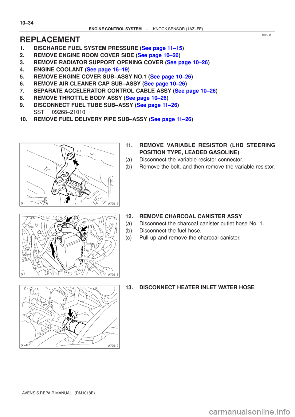
11. REMOVE VARIABLE RESISTOR (LHD STEERINGPOSITION TYPE, LEADED GASOLINE)
(a) Disconnect the variable resistor connector.
(b) Remove the bolt, and then remove the variable resistor.
12. REMOVE CHARCOAL CANISTER ASSY
(a) Disconnect the charcoal canister outlet hose No. 1.
(b) Disconnect the fuel hose.
(c) Pull up and remove the charcoal canister.
13. DISCONNECT HEATER INLET WATER HOSE
Page 1839 of 5135

110UX±01
Fuel Tube Connector
A50710
A60083
Fuel Pipe
Clamp No.1
AA
B12941
±
FUEL FUEL SYSTEM(1AZ±FE)
11±19
AVENSIS REPAIR MANUAL (RM1018E)
ON±VEHICLE INSPECTION
1.CHECK FUEL PRESSURE
(a)Discharge the pressure in the fuel system and take pre-
cautions for possible fuel spillage.(See page 11±15)
(b) Check that the battery voltage is above 12 V.
(c) Disconnect the negative (±) battery cable.
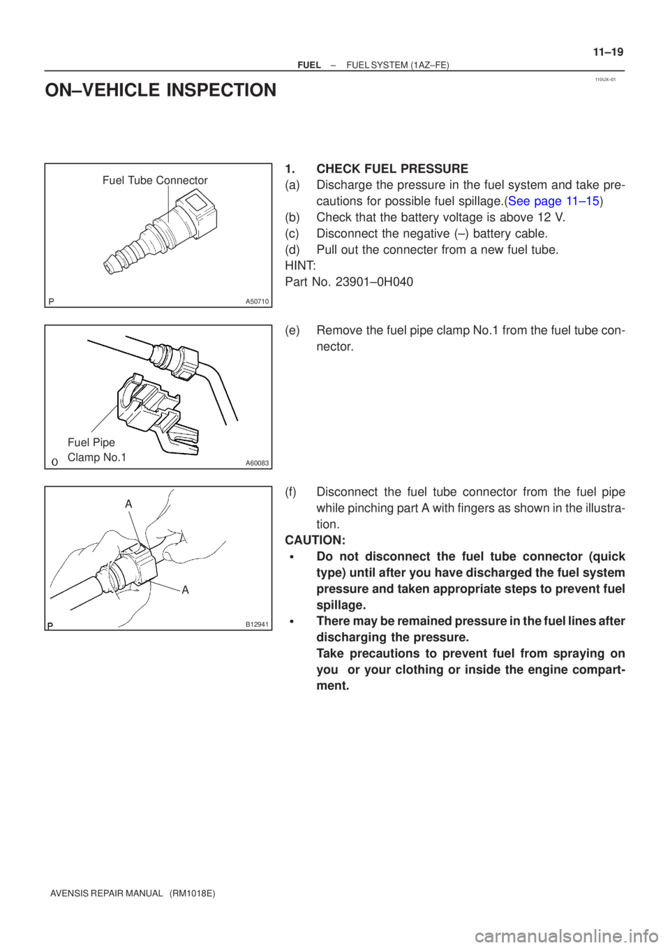
(d) Pull out the connecter from a new fuel tube.
HINT:
Part No. 23901±0H040
(e) Remove the fuel pipe clamp No.1 from the fuel tube con- nector.
(f) Disconnect the fuel tube connector from the fuel pipe while pinching part A with fingers as shown in the illustra-
tion.
CAUTION:
�Do not disconnect the fuel tube connector (quick
type) until after you have discharged the fuel system
pressure and taken appropriate steps to prevent fuel
spillage.
�There may be remained pressure in the fuel lines after
discharging the pressure.
Take precautions to prevent fuel from spraying on
you or your clothing or inside the engine compart-
ment.