Page 735 of 5135

±
DIAGNOSTICS ECD SYSTEM(1CD±FTV)
05±603
AVENSIS REPAIR MANUAL (RM1018E)
DTCP0191FUEL RAIL PRESSURE SENSOR CIRCUIT
RANGE/PERFORMANCE
CIRCUIT DESCRIPTION
Refer to DTCs P0087 on page 05±557.
INSPECTION PROCEDURE
HINT:
�If DTCs ºP0087, P0190, P0192,and P0193º are output simultaneously, manifold absolute pressure
sensor circuit may be open or short. Perform the troubleshooting of DTC ºP0087, P0190, P019\
2,and
P0193º first.
�Read freeze frame data using the hand±held tester. Freeze frame data records the engine conditions
when a malfunction is detected. When troubleshooting, it is useful for deter\
mining whether the vehicle
was running or stopped, the engine was warmed up or not, etc. at the time o\
f the malfunction.
DTC No.DTC Detection ConditionTrouble Area
P0191Voltage output of the fuel pressure sensor for the common rail
is out of the standard range. (1 trip detection logic)�Fuel pressure sensor
1CHECK OTHER DTC OUTPUT(BESIDS DTC P0191)
(a)Read the DTC using the hand±held tester.
Result:
Display (DTC output)Proceed to
Only P0191 is outputA
P0191 and other DTCs are outputB
HINT:
If any other codes besides P0191 are output, perform the troubleshoot for \
those DTCs first.
BGO TO RELEVANT DTC CHART(See page 05±544)
A
REPLACE COMMON RAIL ASSY (FUEL PRESSURE SENSOR) (See page 11±78)
05CPQ±01
Page 736 of 5135
± 20 0 20 40 60 80 100
(± 4) 32 68 104 140 176 212 30
20
10
5
3
2
1
0.5
0.3
0.2
0.1
A67628
Acceptable (Fig.1)
Resistance K�
Temp. �C (�F)
± DIAGNOSTICSECD SYSTEM (1CD±FTV)
05±599
AVENSIS REPAIR MANUAL (RM1018E)
DTC P0180 FUEL TEMPERATURE SENSOR ºAº
CIRCUIT
DTC P0182 FUEL TEMPERATURE SENSOR ºAº
CIRCUIT LOW INPUT
DTC P0183 FUEL TEMPERATURE SENSOR ºAº
CIRCUIT HIGH INPUT
CIRCUIT DESCRIPTION
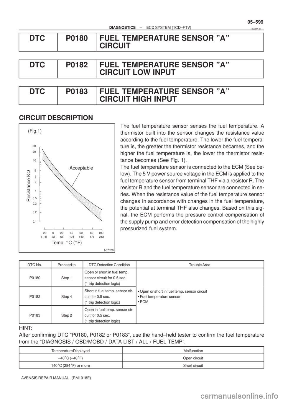
The fuel temperature sensor senses the fuel temperature. A
thermistor built into the sensor changes the resistance value
according to the fuel temperature. The lower the fuel tempera-
ture is, the greater the thermistor resistance becames, and the
higher the fuel temperature is, the lower the thermistor resis-
tance becomes (See Fig. 1).
The fuel temperature sensor is connected to the ECM (See be-
low). The 5 V power source voltage in the ECM is applied to the
fuel temperature sensor from terminal THF via a resistor R. The
resistor R and the fuel temperature sensor are connected in se-
ries. When the resistance value of the fuel temperature sensor
changes in accordance with changes in the fuel temperature,
the potential at terminal THF also changes. Based on this sig-
nal, the ECM performs the pressure control compensation of
the supply pump and error detection compensation of the highly
pressurized fuel system.
DTC No.Proceed toDTC Detection ConditionTrouble Area
P0180Step 1
Open or short in fuel temp.
sensor circuit for 0.5 sec.
(1 trip detection logic)
P0182Step 4
Short in fuel temp. sensor cir-
cuit for 0.5 sec.
(1 trip detection logic)�Open or short in fuel temp. sensor circuit
�Fuel temperature sensor
�ECM
P0183Step 2
Open in fuel temp. sensor cir-
cuit for 0.5 sec.
(1 trip detection logic)
HINT:
After confirming DTC ºP0180, P0182 or P0183º, use the hand±held tester to confirm the fuel temperature
from the ºDIAGNOSIS / OBD/MOBD / DATA LIST / ALL / FUEL TEMPº.
Temperature DisplayedMalfunction
±40�C (±40���Open circuit
140�C (284��� �� ����Short circuit
05CPP±01
Page 738 of 5135
A75743
Fuel Temp. SensorECM
A66104
F18
Wire Harness SideFuel Temp. Sensor Connector
A75742
Fuel Temp. SensorECM
A80450
THFE2
E13
ECM Connector
±
DIAGNOSTICS ECD SYSTEM(1CD±FTV)
05±601
AVENSIS REPAIR MANUAL (RM1018E)
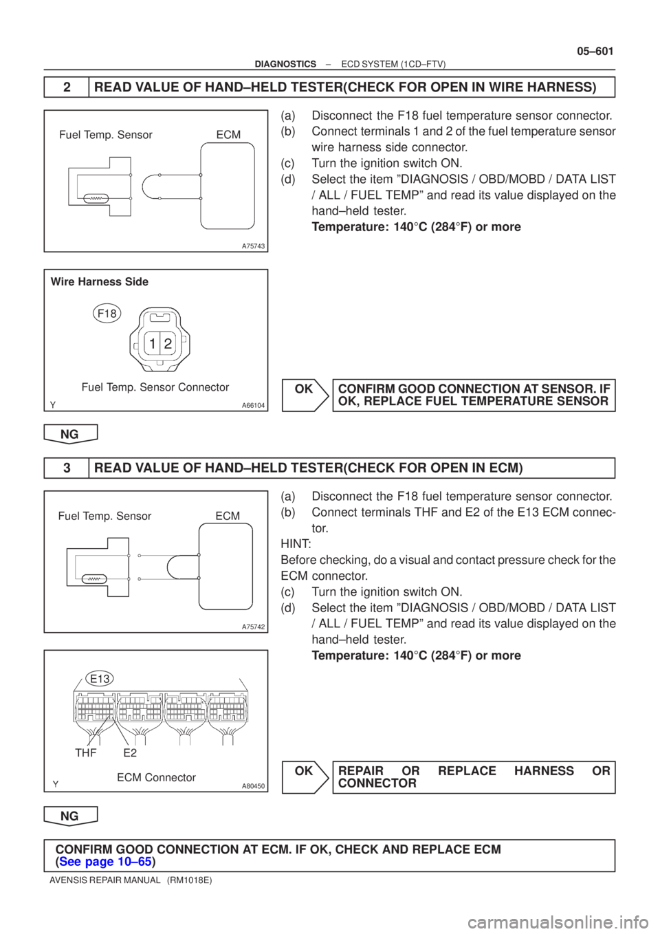
2READ VALUE OF HAND±HELD TESTER(CHECK FOR OPEN IN WIRE HARNESS)
(a)Disconnect the F18 fuel temperature sensor connector.
(b)Connect terminals 1 and 2 of the fuel temperature sensor
wire harness side connector.
(c)Turn the ignition switch ON.
(d)Select the item ºDIAGNOSIS / OBD/MOBD / DATA LIST / ALL / FUEL TEMPº and read its value displayed on the
hand±held tester.
Temperature: 140 �C (284 �F) or more
OKCONFIRM GOOD CONNECTION AT SENSOR. IF OK, REPLACE FUEL TEMPERATURE SENSOR
NG
3READ VALUE OF HAND±HELD TESTER(CHECK FOR OPEN IN ECM)
(a)Disconnect the F18 fuel temperature sensor connector.
(b)Connect terminals THF and E2 of the E13 ECM connec- tor.
HINT:
Before checking, do a visual and contact pressure check for the
ECM connector.
(c)Turn the ignition switch ON.
(d)Select the item ºDIAGNOSIS / OBD/MOBD / DATA LIST / ALL / FUEL TEMPº and read its value displayed on the
hand±held tester.
Temperature: 140 �C (284 �F) or more
OKREPAIR OR REPLACE HARNESS OR CONNECTOR
NG
CONFIRM GOOD CONNECTION AT ECM. IF OK, CHECK AND REPLACE ECM
(See page 10±65)
Page 747 of 5135
±
DIAGNOSTICS ECD SYSTEM(1CD±FTV)
05±685
AVENSIS REPAIR MANUAL (RM1018E)
DTCP2227BAROMETRIC PRESSURE CIRCUIT
RANGE/PERFORMANCE
CIRCUIT DESCRIPTION
Detect the atmospheric pressure using the atmospheric pressure sensor. Followed by the atmospheric pres-
sure, correct the injection timing, the injection volume and the amount of co\
mmon rail internal fuel pressure
and then they create optimum combustion.
DTC No.DTC Detection ConditionTrouble Area
P2227Atmospheric pressure sensor malfunction
(2 trip detection logic)�ECM
INSPECTION PROCEDURE
HINT:
Read freeze frame data using �����\b��������
�� . Freeze frame data records the engine conditions when
a malfunction is detected. When troubleshooting, it is useful for determi\
ning whether the vehicle was running
or stopped, the engine was warmed up or not, etc. at the time of the malfu\
nction.
1CHECK OTHER DTC OUTPUT(BESIDES DTC P2227)
(a)Read the DTC using the hand±held tester. Result:
Display (DTC output)Proceed to
P2227 and other DTCs are outputA
Only P2227 is outputB
HINT:
If any other codes besides P2227 are output, perform the troubleshooting f\
or those DTCs first.
BREPLACE ECM (See page 10±65)
A
GO TO RELEVANT DTC CHART (See page 05±544)
05CQ6±01
Page 748 of 5135
05±684
±
DIAGNOSTICS ECD SYSTEM(1CD±FTV)
AVENSIS REPAIR MANUAL (RM1018E)
DTCP2226BAROMETRIC PRESSURE CIRCUIT
DTCP2228BAROMETRIC PRESSURE CIRCUIT LOW INPUT
DTCP2229BAROMETRIC PRESSURE CIRCUIT HIGH INPUT
CIRCUIT DESCRIPTION
Detect the atmospheric pressure using the atmospheric pressure sensor. Followed by the atmospheric pres-
sure, correct the injection timing, the injection volume and the amount of co\
mmon rail internal fuel pressure
and then they create optimum combustion.
DTC No.DTC Detection ConditionTrouble Area
P2226
P2228
P2229
ECM malfunction (1 trip detection logic)�ECM
INSPECTION PROCEDURE
HINT:
Read freeze frame data using �����\b��������
�� . Freeze frame data records the engine conditions when
a malfunction is detected. When troubleshooting, it is useful for determi\
ning whether the vehicle was running
or stopped, the engine was warmed up or not, etc. at the time of the malfu\
nction.
REPLACE ECM (See page 10±65)
05CQ5±01
Page 757 of 5135

A81485
Fuel Pressure
Pressure Discharge Valve Operation Under Sudden Deceleration
Pressure Discharge Valve w/o Pressure Discharge Valve
Close
Accelerator Pedal
Opening Angle
Open
Close
Open
w/ Pressure Discharge Valve
TargetFuel Pressure TimeLong Time
±
DIAGNOSTICS ECD SYSTEM(1CD±FTV)
05±663
AVENSIS REPAIR MANUAL (RM1018E)
DTCP1271FUEL REGULATOR CIRCUIT MALFUNCTION
(EDU DRIVE)
DTCP1272FUEL PRESSURE REGULATOR MALFUNCTION
HINT:
�For more information on the pressure discharge valve and the common rail sy\
stem, see page 05±517.
�For more information on the EDU, see page 05±604.
�If P1271 and/or P1272 are present, use the diagnostic trouble code matrix for fuel syste\
m, see page
05±517.
CIRCUIT DESCRIPTION
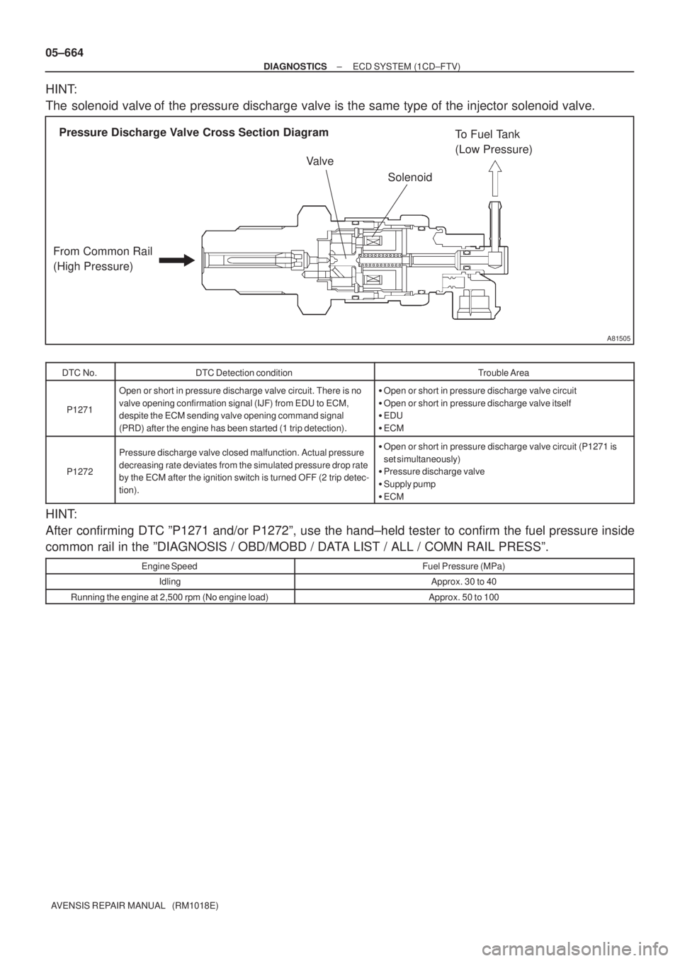
The ECM controls the internal fuel pressure of the common rail by opening a\
nd closing the pressure dis-
charge valve. When sudden deceleration is occurred, the internal fuel pressure will temporarily become
higher than usual and combustion noise may result, therefore the ECM will open the valve temporarily to
discharge the pressure inside the common rail. Also, the pressure discharge valve open\
s when the ignition
switch is turned OFF, and the internal pressure is then promptly discharged.
05CQ1±01
Page 758 of 5135
A81505
Pressure Discharge Valve Cross Section Diagram
From Common Rail
(High Pressure)To Fuel Tank
(Low Pressure)
Valve
Solenoid
05±664
± DIAGNOSTICSECD SYSTEM (1CD±FTV)
AVENSIS REPAIR MANUAL (RM1018E)
HINT:
The solenoid valve of the pressure discharge valve is the same type of the injector solenoid valve.
DTC No.DTC Detection conditionTrouble Area
P1271
Open or short in pressure discharge valve circuit. There is no
valve opening confirmation signal (IJF) from EDU to ECM,
despite the ECM sending valve opening command signal
(PRD) after the engine has been started (1 trip detection).�Open or short in pressure discharge valve circuit
�Open or short in pressure discharge valve itself
�EDU
�ECM
P1272
Pressure discharge valve closed malfunction. Actual pressure
decreasing rate deviates from the simulated pressure drop rate
by the ECM after the ignition switch is turned OFF (2 trip detec-
tion).�Open or short in pressure discharge valve circuit (P1271 is
set simultaneously)
�Pressure discharge valve
�Supply pump
�ECM
HINT:
After confirming DTC ºP1271 and/or P1272º, use the hand±held tester to confirm the fuel pressure inside
common rail in the ºDIAGNOSIS / OBD/MOBD / DATA LIST / ALL / COMN RAIL PRESSº.
Engine SpeedFuel Pressure (MPa)
IdlingApprox. 30 to 40
Running the engine at 2,500 rpm (No engine load)Approx. 50 to 100
Page 759 of 5135
A81500
P1271 Malfunction Detection
ECMCommand Signal (PRD)
EDU
Confirmation Signal (IJF)
Pressure Discharge Valve
Command Signal
Pressure Discharge Valve
Confirmation SignalPRD
IJFON
OFF
Normal
Abnormal
± DIAGNOSTICSECD SYSTEM (1CD±FTV)
05±665
AVENSIS REPAIR MANUAL (RM1018E)
MONITOR DESCRIPTION
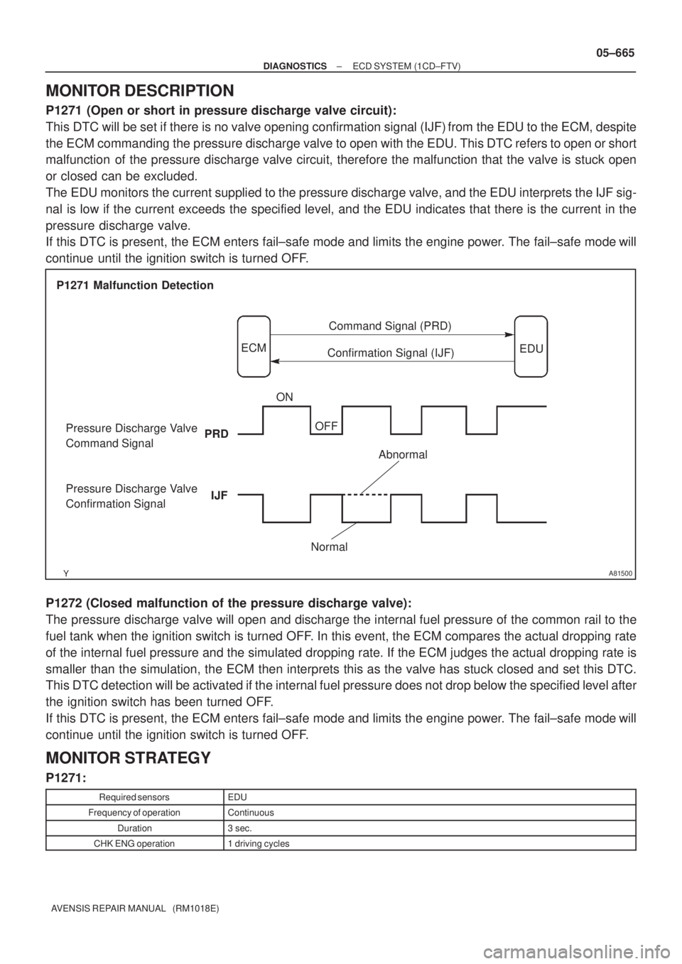
P1271 (Open or short in pressure discharge valve circuit):
This DTC will be set if there is no valve opening confirmation signal (IJF) from the EDU to the ECM, despite
the ECM commanding the pressure discharge valve to open with the EDU. This DTC refers to open or short
malfunction of the pressure discharge valve circuit, therefore the malfunction that the valve is stuck open
or closed can be excluded.
The EDU monitors the current supplied to the pressure discharge valve, and the EDU interprets the IJF sig-
nal is low if the current exceeds the specified level, and the EDU indicates that there is the current in the
pressure discharge valve.
If this DTC is present, the ECM enters fail±safe mode and limits the engine power. The fail±safe mode will
continue until the ignition switch is turned OFF.
P1272 (Closed malfunction of the pressure discharge valve):
The pressure discharge valve will open and discharge the internal fuel pressure of the common rail to the
fuel tank when the ignition switch is turned OFF. In this event, the ECM compares the actual dropping rate
of the internal fuel pressure and the simulated dropping rate. If the ECM judges the actual dropping rate is
smaller than the simulation, the ECM then interprets this as the valve has stuck closed and set this DTC.
This DTC detection will be activated if the internal fuel pressure does not drop below the specified level after
the ignition switch has been turned OFF.
If this DTC is present, the ECM enters fail±safe mode and limits the engine power. The fail±safe mode will
continue until the ignition switch is turned OFF.
MONITOR STRATEGY
P1271:
Required sensorsEDU
Frequency of operationContinuous
Duration3 sec.
CHK ENG operation1 driving cycles