Page 4362 of 5135

S01196S01699
30
20
10
5
3
02040 0.1 1
0.3
0.2 0.52
60 80100 −20
(−4) (104) (140) (176) (32) (68) (212)
A81700
Ohmmeter
Acceptable
Temperature_C(_F)
Resistance K�
A56992
E2
PIM
VC T5
Wire Harness Side:
Manifold Absolute
Pressure Sensor Connector
Front View
A81088
PIM
VC
E2E12ECM Connector E13
05−520
− DIAGNOSTICSECD SYSTEM (1CD−FTV)(From September, 2003)
AVENSIS Supplement (RM1045E)
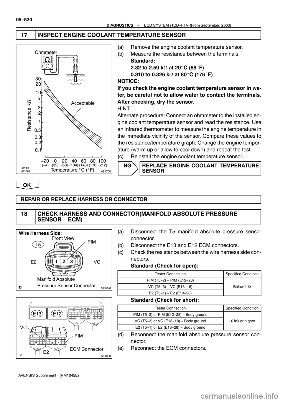
17 INSPECT ENGINE COOLANT TEMPERATURE SENSOR
(a) Remove the engine coolant temperature sensor.
(b) Measure the resistance between the terminals.
Standard:
2.32 to 2.59 k�at 20_C (68_F)
0.310 to 0.326 k�at 80_C(176_F)
NOTICE:
If you check the engine coolant temperature sensor in wa-
ter, be careful not to allow water to contact the terminals.
After checking, dry the sensor.
HINT:
Alternate procedure: Connect an ohmmeter to the installed en-
gine coolant temperature sensor and read the resistance. Use
an infrared thermometer to measure the engine temperature in
the immediate vicinity of the sensor. Compare these values to
the resistance/temperature graph. Change the engine temper-
ature (warm up or allow to cool down) and repeat the test.
(c) Reinstall the engine coolant temperature sensor.
NG REPLACE ENGINE COOLANT TEMPERATURE
SENSOR
OK
REPAIR OR REPLACE HARNESS OR CONNECTOR
18 CHECK HARNESS AND CONNECTOR(MANIFOLD ABSOLUTE PRESSURE
SENSOR−ECM)
(a) Disconnect the T5 manifold absolute pressure sensor
connector.
(b) Disconnect the E13 and E12 ECM connectors.
(c) Check the resistance between the wire harness side con-
nectors.
Standard (Check for open):
Tester ConnectionSpecified Condition
PIM (T5−2)−PIM (E12−28)
VC (T5−3)−VC (E13−18)Below1�
E2 (T5−1)−E2 (E13−28)
Standard (Check for short):
Tester ConnectionSpecified Condition
PIM (T5−2) or PIM (E12−28)−Body ground
VC (T5−3) or VC (E13−18)−Body ground10k�or higher
E2 (T5−1)orE2(E13−28)−Body ground
g
(d) Reconnect the manifold absolute pressure sensor con-
nector.
(e) Reconnect the ECM connectors.
Page 4363 of 5135
A78431
Crankshaft Position Sensor Component Side:
C4
− DIAGNOSTICSECD SYSTEM (1CD−FTV)(From September, 2003)
05−521
AVENSIS Supplement (RM1045E)
NG REPAIR OR REPLACE HARNESS OR
CONNECTOR
OK
REPLACE MANIFOLD ABSOLUTE PRESSURE SENSOR
19 INSPECT CRANKSHAFT POSITION SENSOR
(a) Disconnect the C4 crankshaft position sensor connector.
(b) Measure the resistance between terminals1and 2.
Standard:
Tester ConnectionSpecified Condition
121,630 to 2,740�at cold1−22,065 to 3,225�at hot
NOTICE:
”Cold” and ”Hot” shown above mean the temperature of
the coils themselves. ”Cold” is from−10_C(14_F) to 50_C
(122_F) and ”Hot” is from 50_C(122_F) to100_C(212_F).
(c) Reconnect the crankshaft position sensor connector.
NG REPLACE CRANKSHAFT POSITION SENSOR
OK
REPAIR OR REPLACE HARNESS OR CONNECTOR
Page 4364 of 5135

A84847
EP1EP2VPA2
VCP1
VPA1VCP2 A20
Wire Harness Side (RHD):
Front View Accelerator Pedal Position Sensor
Connector
A84847
EP1
EP2VPA2
VCP1
VPA1 VCP2 A20 Accelerator Pedal Position Sensor
Connector
Wire Harness Side (LHD):
Front View
A81091
E9
ECM ConnectorVPA
VCPA
VPA2
EPA2
VCP2EPA
05−522
− DIAGNOSTICSECD SYSTEM (1CD−FTV)(From September, 2003)
AVENSIS Supplement (RM1045E)
20 CHECK HARNESS AND CONNECTOR(ACCELERATOR PEDAL POSITION
SENSOR−ECM)
(a) Disconnect the A20 accelerator pedal position sensor
connector.
(b) Disconnect E9 the ECM connector.
(c) Check the resistance between the wire harness side con-
nectors.
Standard (Check for open) (RHD):
Tester ConnectionSpecified Condition
VPA1(A20−5)−VPA (E9−22)
EP1(A20−1)−EPA (E9−28)
VCP1(A20−4)−VCPA (E9−26)Below1�VPA2 (A20−2)−VPA2 (E9−23)Below1�
EP2 (A20−3)−EPA2 (E9−29)
VCP2 (A20−6)−VCP2 (E9−27)
Standard (Check for open) (LHD):
Tester ConnectionSpecified Condition
VPA1(A20−5)−VPA (E9−22)
EP1(A20−3)−EPA (E9−28)
VCP1(A20−6)−VCPA (E9−26)Below1�VPA2 (A20−2)−VPA2 (E9−23)Below1�
EP2 (A20−1)−EPA2 (E9−29)
VCP2 (A20−4)−VCP2 (E9−27)
Standard (Check for short) (RHD):
Tester ConnectionSpecified Condition
VPA1(A20−5) or VPA (E9−22)−Body ground
EP1(A20−1) or EPA (E9−28)−Body ground
VCP1(A20−4) or VCPA (E9−26)−Body ground10k�orhigherVPA2 (A20−2) or VPA2 (E9−23)−Body ground10k�or higher
EP2 (A20−3) or EPA2 (E9−29)−Body ground
VCP2 (A20−6) or VCP2 (E9−27)−Body ground
Standard (Check for short) (LHD):
Tester ConnectionSpecified Condition
VPA1(A20−5) or VPA (E9−22)−Body ground
EP1(A20−3) or EPA (E9−28)−Body ground
VCP1(A20−6) or VCPA (E9−26)−Body ground10k�orhigherVPA2 (A20−2) or VPA2 (E9−23)−Body ground10k�or higher
EP2 (A20−1) or EPA2 (E9−29)−Body ground
VCP2 (A20−4) or VCP2 (E9−27)−Body ground
(d) Reconnect the accelerator pedal position sensor connec-
tor.
(e) Reconnect the ECM connector.
NG REPAIR OR REPLACE HARNESS OR
CONNECTOR
OK
REPLACE ACCELERATOR PEDAL ASSY (ACCELERATOR PEDAL POSITION SENSOR)
(See page10−66 of Pub. No. RM1018E AVENSIS REPAIR MANUAL)
Page 4365 of 5135

30
20
1 0
5
3
2
1
0.5
0.3
0.2
0. 1
−20 0
20 40 60
80 100
F 1474 1(− 4) ( 104) ( 140) ( 176)
(32) (68) (2 12)
30
20
1 0
0.5
0.3
0.2
0. 1
−20
20 40 60
80 100
F 1474 1(− 4) ( 104) ( 140) ( 176)
(32) (68) (2 12)
A56276
Temperature _ C( _ F)
Resistance k �
Acceptable
A79038
E2S PCR2 VC2
VC PC E2
Fuel Pressure Sensor
Component Side:
F16
−
DIAGNOSTICS ECD SYSTEM (1CD −FTV)(From September, 2003)
05 −523
AVENSIS Supplement (RM 1045E)
21 INSPECT DIESEL TURBO INLET AIR TENPERATURE SENSOR
(a) Remove the diesel turbo inlet air temperature sensor.
(b) Measure the resistance between the terminals.
Standard:
2.21 to 2.65 k � at 20 _C (68 _F)
(c) Reinstall the diesel turbo inlet air temperature sensor.
NG REPLACE DIESEL TURBO INLET AIR TENPERATURE SENSOR
OK
REPAIR OR REPLACE HARNESS OR CONNECTOR
22 INSPECT COMMON RAIL ASSY(FUEL PRESSURE SENSOR)
(a) Disconnect the F 16 fuel pressure sensor connector.
(b) Measure the resistance between each terminal of the fuel
pressure sensor connector.
Standard:
Tester ConnectionSpecified Condition
PC (F 16− 5) − E2 (F 16− 4)16.4 k � or less
PCR2 (F 16− 2) − E2S (F 16− 3)16.4 k � or less
PC (F 16− 5) − VC (F 16− 6)3k � or less
PCR2 (F 16− 2) − VC2 (F 16−1 )3k � or less
(c) Reconnect the fuel pressure sensor connector.
NG REPLACE COMMON RAIL ASSY (FUEL PRES- SURE SENSOR) (See page 11− 67)
OK
Page 4366 of 5135

A80452
PCR1E
13
ECM Connector
E
12PCR2
E2VCS
E2S
VC
A80453
E2
PCR2
F
16
Wire Harness Side:
Fuel Pressure Sensor Connector
VC2
PCE2S
VC
Front View
05 −524
−
DIAGNOSTICS ECD SYSTEM (1CD −FTV)(From September, 2003)
AVENSIS Supplement (RM 1045E)
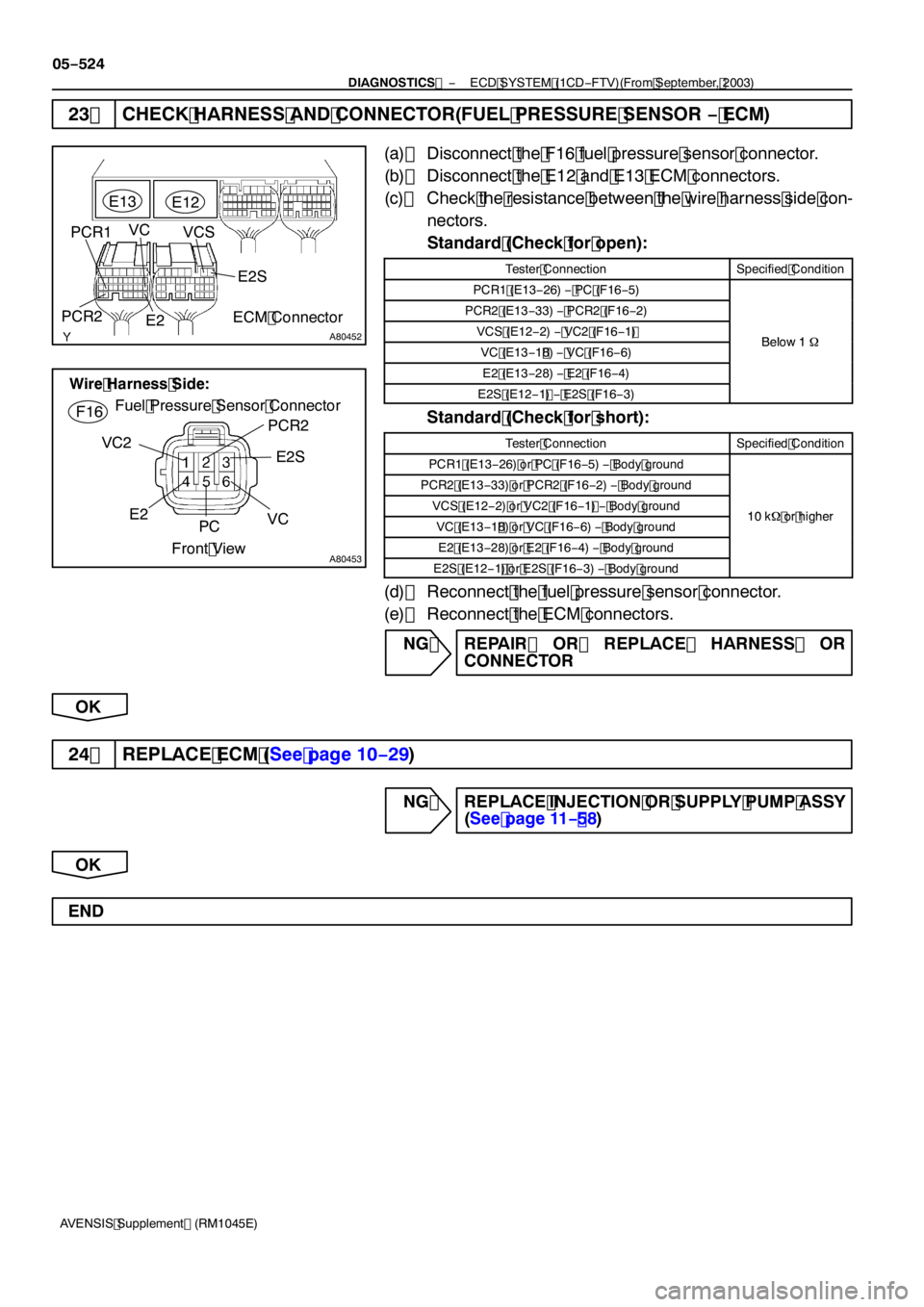
23 CHECK HARNESS AND CONNECTOR(FUEL PRESSURE SENSOR − ECM)
(a) Disconnect the F 16 fuel pressure sensor connector.
(b) Disconnect the E 12 and E 13 ECM connectors.
(c) Check the resistance between the wire harness side con-
nectors.
Standard (Check for open):
Tester ConnectionSpecified Condition
PCR1 (E 13− 26) − PC (F 16− 5)
PCR2 (E 13− 33) − PCR2 (F 16− 2)
VCS (E 12− 2) − VC2 (F 16−1 )Below1�VC (E 13−1 8)− VC (F 16− 6)Below 1�
E2 (E 13− 28) − E2 (F 16− 4)
E2S (E 12−1 )− E2S (F 16− 3)
Standard (Check for short):
Tester ConnectionSpecified Condition
PCR 1 (E 13− 26) or PC (F 16− 5) − Body ground
PCR2 (E 13− 33) or PCR2 (F 16 − 2) − Body ground
VCS (E 12− 2) or VC2 (F 16 −1 )− Body ground10 k � or higherVC (E 13−1 8) or VC (F 16− 6) − Body ground10k � or higher
E2 (E 13− 28) or E2 (F 16− 4) − Body ground
E2S (E 12−1 ) or E2S (F 16− 3) − Body ground
(d) Reconnect the fuel pressure sensor connector.
(e) Reconnect the ECM connectors.
NG REPAIR OR REPLACE HARNESS OR CONNECTOR
OK
24 REPLACE ECM (See page 10− 29)
NG REPLACE INJECTION OR SUPPLY PUMP ASSY
(See page 11− 58)
OK
END
Page 4377 of 5135

05−484
−
DIAGNOSTICS ECD SYSTEM (1CD −FTV)(From September, 2003)
AVENSIS Supplement (RM 1045E)
DTC P2237 OXYGEN (A/F) SENSOR PUMPING
CURRENT CIRCUIT/OPEN (FOR A/F
SENSOR)(BANK1 SENSOR 1)
DTC P2238 OXYGEN (A/F)SENSOR PUMPING CURRENT CIRCUIT LOW (FOR A/F SENSOR)(BANK 1
SENSOR 1)
DTC P2239 OXYGEN (A/F) SENSOR PUMPING CURRENT CIRCUIT HIGH (FOR A/F
SENSOR)(BANK1 SENSOR 1)
HINT:
S For more information on the A/F sensor and TOYOTA D −CAT (* 1) system, see page 05 −255.
S If P2237, P2238 and/or P2239 is present, refer to the diagnostic trouble codes (DTCs) table for TOYO-
TA D −CAT system on page 05 −255.
S These DTCs are recorded when A/F sensor has malfunction, although the caption is the oxygen sen-
sor.
* 1 : Diesel Clean Advanced Technology.
CIRCUIT DESCRIPTION
Refer to DTC P003 1 on page 05 −305.
DTC No.DTC Detecting ConditionTrouble Area
P2237ECM internal error ( 10 seconds)
( 1 trip detection logic)S ECM
P2238
S A/F sensor circuit low (bank 1 sensor 1)
AF+ is less than 04 V for 50 seconds or more
Main trouble area: Open in A/F sensor circuit
S Open or short in A/F sensor circuit
S A/F sensor
S A/F sensor heaterP2238AF+ is less than 0.4 V for 5.0 seconds or more
( 1 trip detection logic)S A/F sensor heater
S A/F sensor heater relay
S A/F sensor heater and relay circuit
S ECM
P2239
S A/F sensor circuit high (bank 1 sensor 1)
AF+ is more than 44 V for 50 seconds or more
Main trouble area: Short in A/F sensor circuit
S Open or short in A/F sensor circuit
S A/F sensor
S A/F sensor heaterP2239AF+ is more than 4.4 V for 5.0 seconds or more
( 1 trip detection logic)S A/F sensor heater
S A/F sensor heater relay
S A/F sensor heater and relay circuit
S ECM
MONITOR DESCRIPTION
The A/F sensor has a characteristic that it varies its voltage output in proportion to the air −fuel ratio. If imped-
ance (alternating current resistance) or voltage output of the sensor extraordinarily deviates from the stan-
dard range, the ECM interprets this as an open or short malfunction of the A/F sensor circuit.
WIRING DIAGRAM
Refer to DTC P003 1 on page 05 −305.
05I7U −01
Page 4378 of 5135

A87894
AF− AF+
A34
Front View
Component Side
(w/ Headlight Beam Level Control):
1
2
3
4
HT
+B
A/F Sensor
Connector
A87894
AF−
AF+
A34
Front View
HT +B
1
2
3
4
Component Side
(w/o Headlight Beam Level Control):
A/F Sensor
Connector
−
DIAGNOSTICS ECD SYSTEM (1CD −FTV)(From September, 2003)
05 −485
AVENSIS Supplement (RM 1045E)
INSPECTION PROCEDURE
HINT:
Read freeze frame data using the hand−held tester. Freeze frame data records the engine conditions when
a malfunction is detected. When troubleshooting, freeze frame data can help determine if the vehicle was
running or stopped, if the engine was warmed up or not, if the air −fuel ratio was lean or rich, and other data
from the time the malfunction occurred.
1 CHECK OTHER DTC(IN ADDITION TO P2237)
(a) Connect the hand −held tester to the DLC3.
(b) Turn the ignition switch to ON and turn the hand −held tester ON.
(c) Select the item ”DIAGNOSIS / OBD/MOBD / DTC INFO / CURRENT CODES”.
(d) Read DTCs.
Result:
Display (DTC output)Proceed to
P2237 and P2238 and/or P2239A
P2237B
B REPLACE ECM (See page 10− 29)
A
2 INSPECT AIR FUEL RATIO SENSOR(RESISTANCE)
(a) Disconnect the A34 A/F sensor connector.
(b) Measure the resistance between the terminals of the A/F sensor.
Resistance (w/ Headlight beam level control):
Tester ConnectionSpecified Condition
HT (1) − +B (2)0.86 to 1.1 � at 20 _C (68 _F)
Resistance (w/o Headlight beam level control):
Tester ConnectionSpecified Condition
HT (2) −+B ( 1)0.86 to 1.1 � at 20 _C (68 _F)
(c) Reconnect the A/F sensor connector.
NG REPLACE AIR FUEL RATIO SENSOR
OK
Page 4379 of 5135
B16200
05−486
− DIAGNOSTICSECD SYSTEM (1CD−FTV)(From September, 2003)
AVENSIS Supplement (RM1045E)
3 INSPECT AIR FUEL RATIO SENSOR HEATER RELAY
(a) Remove the A/F sensor heater relay.
(b) Check for continuity in the A/F sensor heater relay.
Standard:
Tester ConnectionSpecified Condition
1−2Continuity
No continuity
3−5Continuity
(Apply battery voltage to terminals1and 2)
(c) Reinstall the A/F sensor heater relay.
NG REPLACE AIR FUEL RATIO SENSOR HEATER
RELAY
OK