Page 1210 of 5135

4CHECK HARNESS AND CONNECTO")
������I37588
B5
GND
1234
I36144
BLW
A16A15
I31456
GND
2V/
Division
500 �s sec. / Division
05±1150
±
DIAGNOSTICS AIR CONDITIONING SYSTEM
AVENSIS REPAIR MANUAL (RM1018E)
4CHECK HARNESS AND CONNECTOR(BLOWER MOTOR CONTROL ± BODY GROUND)
(a)Check for an open circuit in harness and connector be-
tween terminal GND of blower motor control and body
ground (See page 01±32).
NGREPAIR OR REPLACE HARNESS OR CONNECTOR
OK
5INSPECT AIR CONDITIONING AMPLIFIER(BLW)
(a)Remove the A/C amplifier with connectors being con- nected.
(b)Turn the ignition switch ON.
(c)Blower switch is ON.
(d)Measure the waveform between terminal BLW of A/C am- plifier and body ground.
OK: Pulse generation
HINT:
�The correct waveform is as shown.
�Waveform varies with blower level.
NGREPLACE AIR CONDITIONING AMPLIFIER
OK
6CHECK HARNESS OR CONNECTOR(A/C AMPLIFIER ± BLOWER MOTOR CONTROL)
(a)Check for an open or short circuit in harness and connector between A/C amplifier and\
blower motor
control (See page 01±32).
NG REPAIR OR REPLACE HARNESS ORCONNECTOR
OK
REPLACE BLOWER MOTOR CONTROL
Page 1211 of 5135
I35394
Driver Side J/B
L2
DP
1
DN
5
DH B±G (*1)
B±L (*2)
G±Y9
DA
1
DH4
DF2
DF34
DA HTR HTR Relay
12
53
4L±B
To
Blower Motor GR±R
W±BA1617 A/C Control Assembly
HR
W±B
AM153
12IG1 Relay
I13
Ignition SW
G±R G±Y
AM1 IG1 1 3
G±Y
B±L (*2)1
ED1W (*2)Engine Room R/B No.3
3
3140A
ALT
1 23B (*2)
B±G (*1)W (*2) Engine Room R/B
No.1 & Engine Room J/B No.1
L
11B1 HTR
1 2
Engine Room R/B No.4
1
4C
4D1120A ALT (*3)
100A ALT (*4)
4B1
B±G (*1)
B (*2)
W±B
W±B FL MAIN
BatteryIJ
*1: Gasoline
*2: 1CD±FTV*3: 1AZ±FSE, 1AZ±FE
*4: 1ZZ±FE, 3ZZ±FE 05±1146
± DIAGNOSTICSAIR CONDITIONING SYSTEM
AVENSIS REPAIR MANUAL (RM1018E)
HEATER RELAY CIRCUIT
CIRCUIT DESCRIPTION
The heater relay is switched on by signals from the A/C amplifier. It supplies power to the blower motor.
WIRING DIAGRAM
050U2±12
Page 1212 of 5135

INSPECTION PROCEDURE
1 CHECK FUSE(HTR FUSE)
(a) Remove the HTR fuse from the driver side J/B an")
E32993
I36144
HR
A16A15
± DIAGNOSTICSAIR CONDITIONING SYSTEM
05±1147
AVENSIS REPAIR MANUAL (RM1018E)
INSPECTION PROCEDURE
1 CHECK FUSE(HTR FUSE)
(a) Remove the HTR fuse from the driver side J/B and engine room J/B.
(b) Check for the continuity of HTR fuse.
NG REPLACE FUSE
OK
2 INSPECT HEATER RELAY
(a) Check for the continuity between each pair of terminals of
cooler relay assy, as shown in the chart.
Standard:
Terminal No.Specified condition
No continuity
3 ± 5Less than 1 �
(When battery voltage applied to terminals 1 and 2)
Less than 1 �
3 ± 4No continuity
(When battery voltage applied to terminals 1 and 2)
1 ± 2Approx. 1.3 k�
NG REPLACE HEATER RELAY
OK
3 CHECK HARNESS AND CONNECTOR(A/C AMPLIFIER ± BATTERY)
(a) Remove the A/C amplifier with connectors being con-
nected.
(b) Measure the voltage between terminal HR of A/C amplifi-
er and body ground when ignition switch is ON and OFF.
Standard:
Ignition switch positionBlower switch positionVoltage (V)
OFFOFF0
ONONBelow 1.0
ONOFF10 to 14
NG REPAIR OR REPLACE HARNESS OR
CONNECTOR
OK
PROCEED TO NEXT CIRCUIT INSPECTION SHOWN ON PROBLEM SYMPTOMS TABLE
Page 1213 of 5135
������
I36744
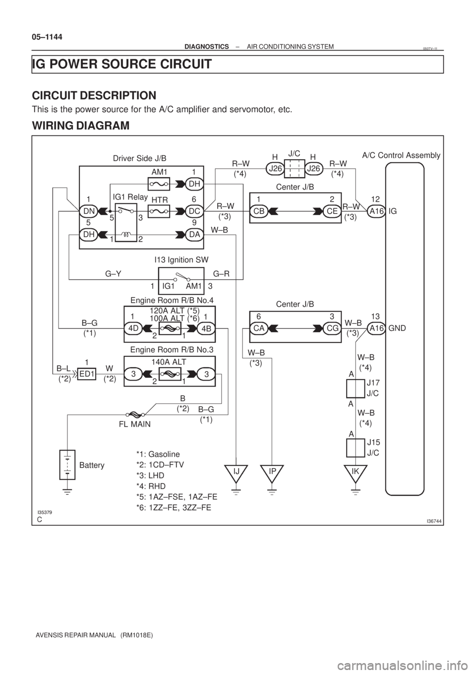
Driver Side J/BA/C Control Assembly
1
DN6
DC AM1
HTR1
DH
5
DH9
DAW±BR±W
(*3)R±W
(*4)J26 J26R±W
(*4) HHJ/C
1
CB2
CER±W
(*3)A1612
IG
I13 Ignition SW
G±Y G±R
IG1 AM1 13Center J/B
6
CA3
CGW±B
(*3)A1613
GND Center J/B
B±G
(*1)53
12
1
4D
1 2 120A ALT (*5)
1
4B
3
1 2 140A ALT
3 B±L
(*2)ED11
W
(*2)
B
(*2)
B±G
(*1)
FL MAIN
Battery
IJ IP IK *1: Gasoline
*2: 1CD±FTV
*3: LHD
*4: RHD
*5: 1AZ±FSE, 1AZ±FE
*6: 1ZZ±FE, 3ZZ±FEW±B
(*4)
A
J15
J/C W±B
(*3) IG1 Relay
Engine Room R/B No.4
Engine Room R/B No.3100A ALT (*6)
W±B
(*4)J17
J/C
AA 05±1144
± DIAGNOSTICSAIR CONDITIONING SYSTEM
AVENSIS REPAIR MANUAL (RM1018E)
IG POWER SOURCE CIRCUIT
CIRCUIT DESCRIPTION
This is the power source for the A/C amplifier and servomotor, etc.
WIRING DIAGRAM
050TV±11
Page 1214 of 5135
I36144
IG
GND
A16A15
± DIAGNOSTICSAIR CONDITIONING SYSTEM
05±1145
AVENSIS REPAIR MANUAL (RM1018E)
INSPECTION PROCEDURE
1 CHECK FUSE(HTR FUSE)
(a) Remove the HTR fuse from the driver side J/B.
(b) Check for the continuity of HTR fuse.
NG REPLACE FUSE
OK
2 CHECK HARNESS AND CONNECTOR(A/C AMPLIFIER ± BATTERY)
(a) Remove the A/C amplifier with connectors being con-
nected.
(b) Turn the ignition switch to ON.
(c) Measure the voltage between terminal IG and GND of the
A/C amplifier.
Standard: 10 to 14 V
NG REPAIR OR REPLACE HARNESS OR
CONNECTOR
OK
PROCEED TO NEXT CIRCUIT INSPECTION SHOWN ON PROBLEM SYMPTOMS TABLE
Page 1215 of 5135
I35395
Fuse Block Center J/BA/C Control Assembly
ECU±B2
66
12CC CF 10 7
W±R W±R
A1624
+B
B±W
IE4 IP145
(*3) (*4)B±W Engine Room R/B No.1 & Engine Room J/B No.1B±G (*1)
B (*2) DCC
11A
1 21
Engine Room R/B No.3
Engine Room J/B No.4
Center J/B B (*2)
B±G (*1)B (*2)
B±G (*1) 33
4A 4B
CG CA W±B (*3) W±B (*3)11
63
A1613
GND
FL MAIN
Battery
IP IKAAA W±B (*4) W±B (*4)J17
J/C
*1: Gasoline
*2: 1CD±FTV*3: LHD
*4: RHDJ15
J/C 05±1142
± DIAGNOSTICSAIR CONDITIONING SYSTEM
AVENSIS REPAIR MANUAL (RM1018E)
BACK±UP POWER SOURCE CIRCUIT
CIRCUIT DESCRIPTION
This is the back±up power source for the A/C amplifier. Power is supplied even when the ignition switch is
off and is used for diagnostic trouble code memory etc.
WIRING DIAGRAM
050TW±10
Page 1216 of 5135
I36144
+BGND
A16A15
± DIAGNOSTICSAIR CONDITIONING SYSTEM
05±1143
AVENSIS REPAIR MANUAL (RM1018E)
INSPECTION PROCEDURE
1 CHECK FUSE(ECU±B2, DCC FUSE)
(a) Remove the ECU±B2 fuse and DCC fuse from the fuse block and engine room J/B.
(b) Check for the continuity of ECU±B2 fuse and DCC fuse.
NG REPLACE FUSE
OK
2 CHECK HARNESS AND CONNECTOR(A/C AMPLIFIER ± BATTERY)
(a) Remove the A/C amplifier with being connected.
(b) Measure the voltage between terminal +B and GND of
A/C amplifier.
Standard: 10 to 14 V
NG REPAIR OR REPLACE HARNESS OR
CONNECTOR
OK
PROCEED TO NEXT CIRCUIT INSPECTION SHOWN ON PROBLEM SYMPTOMS TABLE
Page 1217 of 5135

DTCB0")
������������
��
��
H41439
D SquibAirbag
Sensor
Assy
CenterSpiral
Cable
Sub±assy
Color: Orange
A
B
C
D
E
F
05±1202
±
DIAGNOSTICS SUPPLEMENTAL RESTRAINT SYSTEM
AVENSIS REPAIR MANUAL (RM1018E)
DTCB0101/14OPEN IN D SQUIB CIRCUIT
CIRCUIT DESCRIPTION
The D squib circuit consists of the airbag sensor assy center, the spiral cable sub±assy and the horn button
assy.
This circuit actuates the SRS to deploy when the SRS deployment conditions a\
re fulfilled.
DTC B0101/14 is recorded when an open circuit is detected in the D squib\
circuit.
DTC No.DTC Detecting ConditionTrouble Area
B0101/14
� Open circuit in D+ wire harness or D± wire harness of D
squib
� D squib malfunction
� Spiral cable sub±assy malfunction
� Airbag sensor assy center malfunction�Horn button assy (D squib)
� Spiral cable sub±assy
� Airbag sensor assy center
� Instrument panel wire
WIRING DIAGRAM
See page 05±1198.
INSPECTION PROCEDURE
1 CHECK D SQUIB CIRCUIT(AIRBAG SENSOR ASSY CENTER ± HORN BUTTON
ASSY)
(a) Turn the ignition switch to the LOCK position.
(b) Disconnect the negative (±) terminal cable from the bat-
tery, and wait for at least 90 seconds.
(c) Disconnect the connectors from the airbag sensor assy
center and the horn button assy.
(d) Measure the resistance between D+ and D± of the con- nector ºEº.
OK:
Resistance: Below 1 �
NG Go to step 4
OK
056LY±04

B±L (*2)
G±Y9
DA
1
DH4
DF2
DF34
DA HTR HTR Relay
12
53
4L±B
To
Blower Motor GR±R
W±BA1617 A/C Control Assembly
HR
W±B
AM153
12IG1 Relay
I13
Ign")

INSPECTION PROCEDURE
1 CHECK FUSE(HTR FUSE)
(a) Remove the HTR fuse from the driver side J/B.
(b)")
 (*4)B±W Engine Room R/B No.1 & Engine Room J/B No.1B±G (*1)
B (*2) DCC
11A
1 21
Engine")

INSPECTION PROCEDURE
1 CHECK FUSE(ECU±B2, DCC FUSE)
(a) Remove the ECU±B2 fuse and DCC fuse from")