Page 247 of 5135

(fig. 1)
Acceptable
Resistance k�
± 20 0 20 40 60 80 100
(± 4) 32 68 104 140 176 212 30
20
10
5
3
2
1
0.5
0.3
0.2
0.1
Temp.�C (�F)
(fig. 1)
Acceptable
Resistance k�
± 20 0 20 40 60 80 100
(± 4) 32 68 104 140 176 212 30
20
10
5
3
2
1
0.5
0.3
0.2
0.1
Temp.�C (�F)
FI4741
05±30
± DIAGNOSTICSSFI SYSTEM (1ZZ±FE/3ZZ±FE)
AVENSIS REPAIR MANUAL (RM1018E)
DTC P0110 INTAKE AIR TEMPERATURE CIRCUIT
CIRCUIT DESCRIPTION
The intake air temperature sensor is built into the mass air flow
meter and senses the intake air temperature.
A thermistor built in the sensor changes the resistance value
according to the intake air temperature.
The lower the intake air temperature, the greater the thermistor
resistance value, and the higher the intake air temperature, the
lower the thermistor resistance value (See fig. 1).
The intake air temperature sensor is connected to the ECM
(See below ). The 5 V power source voltage in the ECM is ap-
plied to the intake air temperature sensor from the terminal THA
via resistor R.
That is, the resistor R and the intake air temperature sensor are
connected in series. When the resistance value of the intake air
temperature sensor changes in accordance with changes in the
intake air temperature, the potential at terminal THA also
changes. Based on this signal, the ECM increases the fuel in-
jection volume to improve driveability during cold engine opera-
tion.
DTC No.DTC Detecting ConditionTrouble Area
P0110Open or short in intake air temp. sensor circuit
�Open or short in intake air temp. sensor circuit
�Intake air temp. sensor (built into mass air flow meter)
� ECM
If the ECM detects the DTC ºP0110º, it enters the fail±safe mode in which the intake air temperature is as-
sumed to be 20 �C (68 �F).
HINT:
After confirming DTC ºP0110º, use the hand±held tester to confirm the intake air temperature from the
ºDIAGNOSIS / OBD/MOBD / DATA LIST / ALLº.
Temperature DisplayedMalfunction
±40 �C (±40 �F)Open circuit
140 �C (284 �F) or moreShort circuit
05B3P±02
Page 248 of 5135

A72925
A6
Intake Air Temp. Sensor
(built in Mass Air Flow Meter)
4
5 G±R
BR E2
THA ECM
20
E13
E13 28 5V
R
THA
E2
±
DIAGNOSTICS SFI SYSTEM(1ZZ±FE/3ZZ±FE)
05±31
AVENSIS REPAIR MANUAL (RM1018E)
WIRING DIAGRAM
INSPECTION PROCEDURE
HINT:
�Read freeze frame data using \f���� ����\b�\f��\f�
� Freeze frame data records the engine conditions
when a malfunction is detected. When troubleshooting, it is useful for d\
etermining whether the vehicle
was running or stopped, the engine was warmed up or not, the air±fuel ra\
tio was lean or rich, etc. at
the time of the malfunction.
�If different DTCs that are related to a different system are output simultaneously while terminal E2 is
used as a ground terminal, terminal E2 may be open.
1READ VALUE OF HAND±HELD TESTER(INTAKE AIR TEMPERATURE)
(a)Connect the hand±held tester to the DLC3.
(b)Turn the ignition switch ON.
(c)Select the item ºDIAGNOSIS / OBD/MOBD / DATA LIST / ALL / INTAKE AIRº and read its value dis- played on the hand±held tester.
Temperature: The same as actual intake air temperature
Result:
Temperature DisplayedProceed to
±40 �C (±40 �F)A
140 �C (284 �F) or moreB
OK (Same as present temperature)C
HINT:
�If there is an open circuit, the hand±held tester indicates ±40
C (±40
F).
�If there is a short circuit, the hand±held tester indicates 140
C (284
F) or more.
BGo to step 4
CCHECK FOR INTERMITTENT PROBLEMS (See Page 05±5)
A
Page 262 of 5135
A73818
Crankshaft
Position
Sensor
Camshaft
Position
Sensor
Various
SensorIGT1
IGF
IGT2
IGT3
IGT4 ECM
No. 1 Spark Plug
No. 2 Spark Plug
No. 3 Spark Plug
No. 4 Spark Plug Ignition Coil
Assy No. 1 IgniterFrom Battery
Ignition Coil
Ignition Coil
Assy No. 2
Ignition Coil
Assy No. 3
Ignition Coil
Assy No. 4
TA C
To Tachometer 05±104
± DIAGNOSTICSSFI SYSTEM (1ZZ±FE/3ZZ±FE)
AVENSIS REPAIR MANUAL (RM1018E)DTC No.
DTC Detecting ConditionTrouble Area
P1300
P1305
P1310
P1315
No IGF signal to the ECM while engine is running
�Ignition system
�Open or short in IGF or IGT1 circuit from No. 1 ignition coil
with igniter to ECM
�No.1 ± No.4 ignition coil with igniter
� ECM
Page 272 of 5135

A79413
From
Speed SensorSkid
Control
ECU4±Pulse
Combination
Meter4±Pulse
ECM
A79092
C11
Combination Meter
Junction Connector
17
V±W
E10ECM
V±W
SPD 18
J10
J20 H
*1*2
*1: LHD
*2: RHD J20 J10
*1 *2 HHH 05±98
± DIAGNOSTICSSFI SYSTEM (1ZZ±FE/3ZZ±FE)
AVENSIS REPAIR MANUAL (RM1018E)
DTC P0500 VEHICLE SPEED SENSOR MALFUNCTION
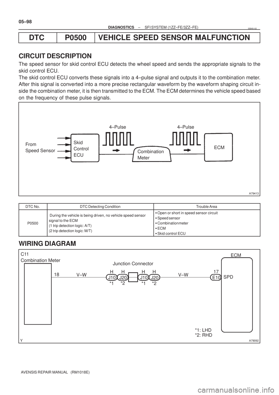
CIRCUIT DESCRIPTION
The speed sensor for skid control ECU detects the wheel speed and sends the appropriate signals to the
skid control ECU.
The skid control ECU converts these signals into a 4±pulse signal and outputs it to the combination meter.
After this signal is converted into a more precise rectangular waveform by the waveform shaping circuit in-
side the combination meter, it is then transmitted to the ECM. The ECM determines the vehicle speed based
on the frequency of these pulse signals.
DTC No.DTC Detecting ConditionTrouble Area
P0500
During the vehicle is being driven, no vehicle speed sensor
signal to the ECM
(1 trip detection logic: A/T)
(2 trip detection logic: M/T)�Open or short in speed sensor circuit
�Speed sensor
�Combination meter
�ECM
�Skid control ECU
WIRING DIAGRAM
05B45±02
Page 273 of 5135

A18294
SPD (+)E1 (±)ECM Connector
E12 E10
A62954
Turn Wheel
4.5±5.5V
0V
±
DIAGNOSTICS SFI SYSTEM(1ZZ±FE/3ZZ±FE)
05±99
AVENSIS REPAIR MANUAL (RM1018E)
INSPECTION PROCEDURE
HINT:
Read freeze frame data using \f���� ����\b�\f��\f�
� Freeze frame data records the engine conditions when
a malfunction is detected. When troubleshooting, it is useful for determi\
ning whether the vehicle was running
or stopped, the engine was warmed up or not, the air±fuel ratio was lea\
n or rich, etc. at the time of the mal-
function.
1CHECK OPERATION OF SPEEDOMETER(SPEEDOMETER OPERATION)
(a)Drive the vehicle and check that the operation of the speedometer in the\
combination meter is normal.
HINT:
The vehicle speed sensor is operating normally if the speedometer display i\
s normal.
NGCHECK SPEEDOMETER CIRCUIT
OK
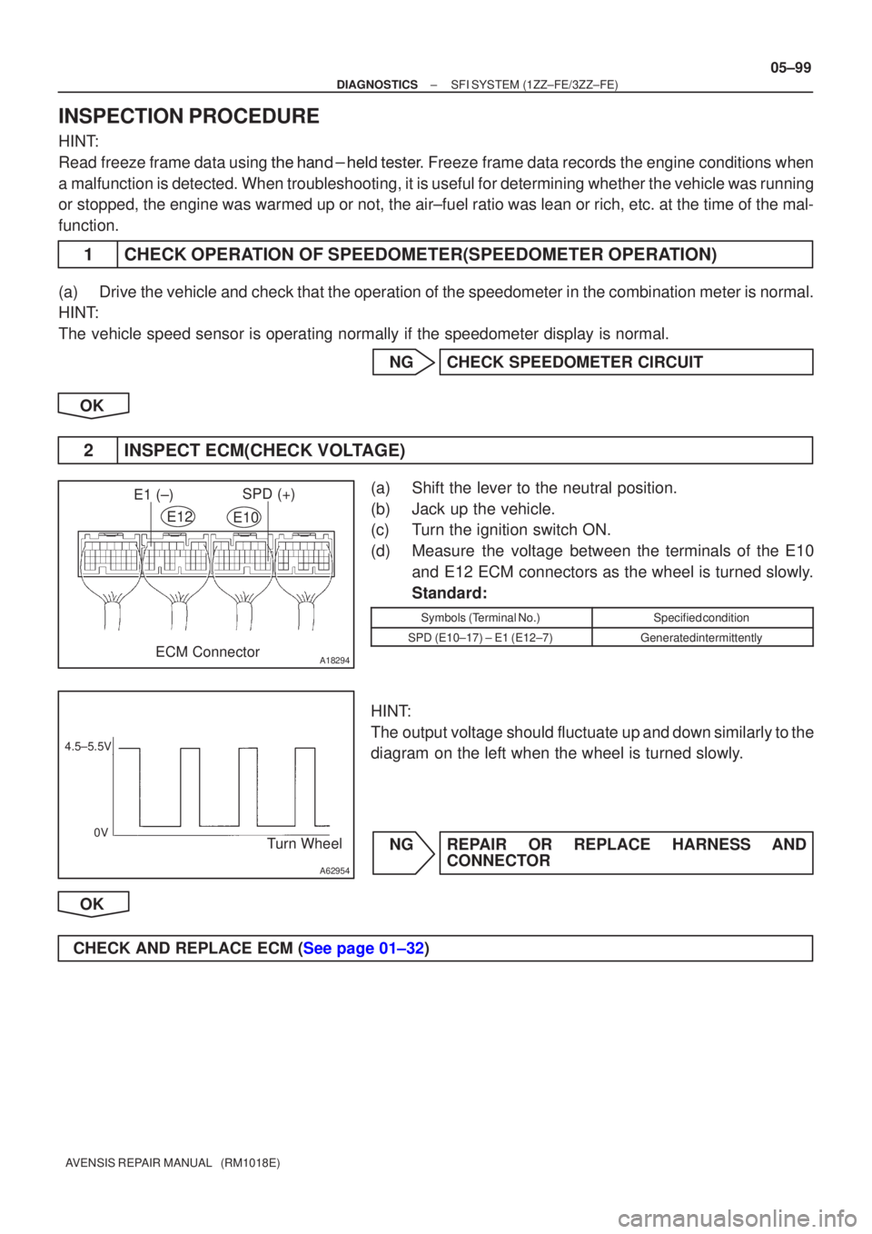
2INSPECT ECM(CHECK VOLTAGE)
(a)Shift the lever to the neutral position.
(b)Jack up the vehicle.
(c)Turn the ignition switch ON.
(d)Measure the voltage between the terminals of the E10 and E12 ECM connectors as the wheel is turned slowly.
Standard:
Symbols (Terminal No.)Specified condition
SPD (E10±17) ± E1 (E12±7)Generated intermittently
HINT:
The output voltage should fluctuate up and down similarly to the
diagram on the left when the wheel is turned slowly.
NGREPAIR OR REPLACE HARNESS AND CONNECTOR
OK
CHECK AND REPLACE ECM (See page 01±32)
Page 278 of 5135

A58692
Waveform of heated oxygen
Sensor in front of CatalystNormal CatalystWaveform of Heated Oxygen
Sensor behind Catalyst
A58693
Engine Speed
2,500 ± 3,000 rpm
Idling
IG SW OFF
Warmed up 3 min. Check Time (a)(b)(c) (d)
± DIAGNOSTICSSFI SYSTEM (1ZZ±FE/3ZZ±FE)
05±91
AVENSIS REPAIR MANUAL (RM1018E)
DTC P0420 CATALYST SYSTEM EFFICIENCY BELOW
THRESHOLD (BANK 1)
CIRCUIT DESCRIPTION
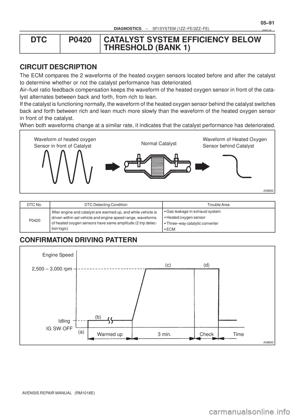
The ECM compares the 2 waveforms of the heated oxygen sensors located before and after the catalyst
to determine whether or not the catalyst performance has deteriorated.
Air±fuel ratio feedback compensation keeps the waveform of the heated oxygen sensor in front of the cata-
lyst alternates between back and forth, from rich to lean.
If the catalyst is functioning normally, the waveform of the heated oxygen sensor behind the catalyst switches
back and forth between rich and lean much more slowly than the waveform of the heated oxygen sensor
in front of the catalyst.
When both waveforms change at a similar rate, it indicates that the catalyst performance has deteriorated.
DTC No.DTC Detecting ConditionTrouble Area
P0420
After engine and catalyst are warmed up, and while vehicle is
driven within set vehicle and engine speed range, waveforms
of heated oxygen sensors have same amplitude (2 trip detec-
tion logic)�Gas leakage in exhaust system
�Heated oxygen sensor
�Three±way catalytic converter
�ECM
CONFIRMATION DRIVING PATTERN
05B43±02
Page 279 of 5135

A58694
OX Signal Waveform (Oscilloscope)
1.0 V
0 V 200 msec. /Division
05±92
±
DIAGNOSTICS SFI SYSTEM(1ZZ±FE/3ZZ±FE)
AVENSIS REPAIR MANUAL (RM1018E)
(a)Connect the hand±held tester to the DLC3, or connect the probe of the oscilloscope between terminals HT1A,
HT1B, OX1A, OX1B and E1 of the ECM connector.
(b)Start the engine and warm it up with all the accessories switched OFF until the engine coolant temperature is
stable.
(c)Run the engine at 2,500 to 3,000 rpm for about 3 min.
(d)After confirming that the waveform of the heated oxygen
sensor (bank 1 sensor 1 (OX)) which oscillates around 0.5
V during feedback to the ECM, check the waveform of the
heated oxygen sensor (bank 1 sensor 2 (OX)).
HINT:
�If there is a malfunction in the system, the waveform of the
heated oxygen sensor (bank 1 sensor 2 (OX)) is similar
to the wave from of the heated oxygen sensor (bank 1
sensor 1 (OX)) snown in the diagram on the left.
�There are some cases that, even though a malfunction
exists, the CHK ENG may not be illuminated.
INSPECTION PROCEDURE
HINT:
Read freeze frame data using \f���� ����\b�\f��\f�
� Freeze frame data records the engine conditions when
a malfunction is detected. When troubleshooting, it is useful for determi\
ning whether the vehicle was running
or stopped, the engine was warmed up or not, the air±fuel ratio was lea\
n or rich, etc. at the time of the mal-
function.
1READ OUTPUT DTC(BESIDES P0420)
(a)Read the DTC using the hand±held tester. Result:
Display (DTC output)Proceed to
Only ºP0420º is outputA
ºP0420º and other DTCs are outputB
HINT:
If any other codes besides ºP0420º are output, perform the troublesh\
ooting for those DTCs first.
BGO TO RELEVANT DTC CHART(See page 05±16)
A
Page 280 of 5135
±
DIAGNOSTICS SFI SYSTEM(1ZZ±FE/3ZZ±FE)
05±93
AVENSIS REPAIR MANUAL (RM1018E)
2CHECK FOR EXHAUST GAS LEAKS
NGREPAIR OR REPLACE
OK
3INSPECT HEATED OXYGEN SENSOR(BANK 1 SENSOR 1) (See Page 12±3)
NG REPAIR OR REPLACE HEATED OXYGEN SENSOR
OK
4INSPECT HEATED OXYGEN SENSOR(BANK 1 SENSOR 2) (See Page 12±3)
NG REPAIR OR REPLACE HEATED OXYGEN SENSOR
OK
REPLACE THREE±WAY CATALYTIC CONVERTER