Page 2823 of 5135
4200G±05
D26951
EXCEPT 1CD±FTV Engine Type:1CD±FTV Engine Type:
������D25280Matchmarks
42±26
±
CLUTCH CLUTCH UNIT (MTM)
AVENSIS REPAIR MANUAL (RM1018E)
OVERHAUL
1. REMOVE MANUAL TRANSAXLE ASSY
(a)1ZZ±FE, 3ZZ±FE Engine (See page 41±15)
(b)1AZ±FE, 1AZ±FSE Engine (See page 41±24)
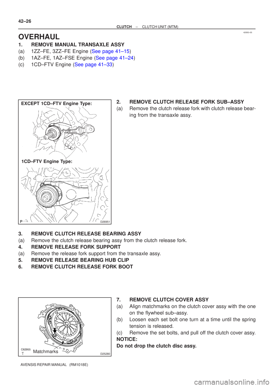
(c)1CD±FTV Engine (See page 41±33) 2. REMOVE CLUTCH RELEASE FORK SUB±ASSY
(a) Remove the clutch release fork with clutch release bear-ing from the transaxle assy.
3. REMOVE CLUTCH RELEASE BEARING ASSY
(a) Remove the clutch release bearing assy from the clutch release fork.
4. REMOVE RELEASE FORK SUPPORT
(a) Remove the release fork support from the transaxle assy.
5. REMOVE RELEASE BEARING HUB CLIP
6. REMOVE CLUTCH RELEASE FORK BOOT 7. REMOVE CLUTCH COVER ASSY
(a) Align matchmarks on the clutch cover assy with the oneon the flywheel sub±assy.
(b) Loosen each set bolt one turn at a time until the spring tension is released.
(c) Remove the set bolts, and pull off the clutch cover assy.
NOTICE:
Do not drop the clutch disc assy.
Page 2825 of 5135
Q01060
D30059
1CD±FTV Engine Type: Others:
Flywheel Side
SST(s)
D26323
SST(s)
Matchmarks 7
1 (Temporally), 4
3
6
2.58
D00205
SST(s)
42±28
± CLUTCHCLUTCH UNIT (MTM)
AVENSIS REPAIR MANUAL (RM1018E)
12. INSPECT CLUTCH RELEASE BEARING ASSY
(a) Turn the release bearing by hand while applying force in
the axial direction.
HINT:
The bearing is permanently lubricated and requires no cleaning
or lubrication.
Replace the release bearing assy as necessary.
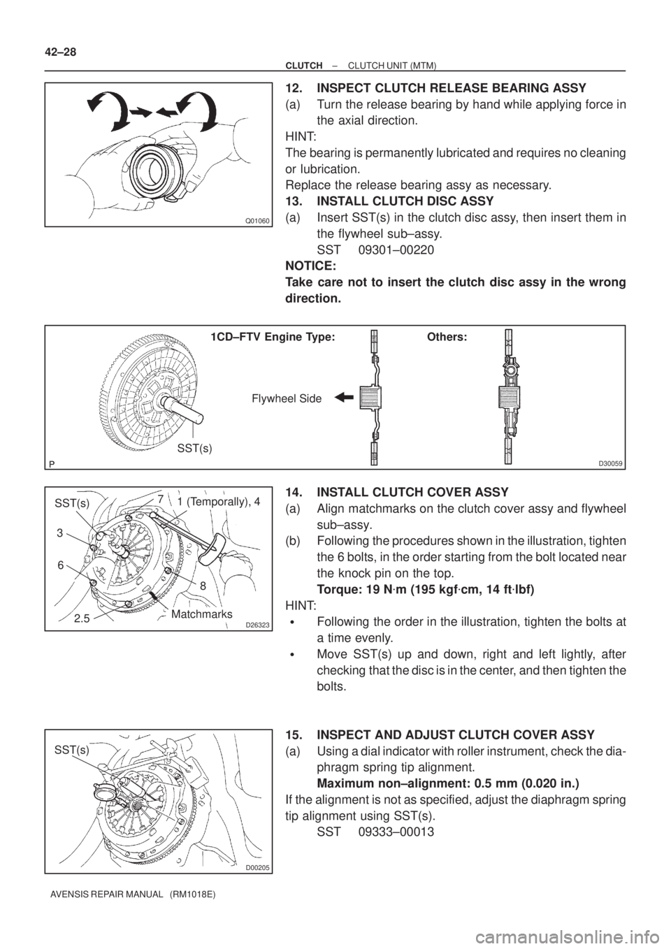
13. INSTALL CLUTCH DISC ASSY
(a) Insert SST(s) in the clutch disc assy, then insert them in
the flywheel sub±assy.
SST 09301±00220
NOTICE:
Take care not to insert the clutch disc assy in the wrong
direction.
14. INSTALL CLUTCH COVER ASSY
(a) Align matchmarks on the clutch cover assy and flywheel
sub±assy.
(b) Following the procedures shown in the illustration, tighten
the 6 bolts, in the order starting from the bolt located near
the knock pin on the top.
Torque: 19 N�m (195 kgf�cm, 14 ft�lbf)
HINT:
�Following the order in the illustration, tighten the bolts at
a time evenly.
�Move SST(s) up and down, right and left lightly, after
checking that the disc is in the center, and then tighten the
bolts.
15. INSPECT AND ADJUST CLUTCH COVER ASSY
(a) Using a dial indicator with roller instrument, check the dia-
phragm spring tip alignment.
Maximum non±alignment: 0.5 mm (0.020 in.)
If the alignment is not as specified, adjust the diaphragm spring
tip alignment using SST(s).
SST 09333±00013
Page 2975 of 5135
H40008
Wire Harness
Diameter
Stripped Wire Harness Section
H42627
L
M
H42628
SST(s) 60±22
± SUPPLEMENTAL RESTRAINT SYSTEMHORN BUTTON ASSY
AVENSIS REPAIR MANUAL (RM1018E)
CAUTION:
�When removing the horn button assy, work must be
started 90 seconds after the ignition switch is turned
to the ºLOCKº position and the negative (±) terminal
cable is disconnected from the battery.
�When storing the horn button assy, keep the upper
surface of the airbag deployment side facing upward.
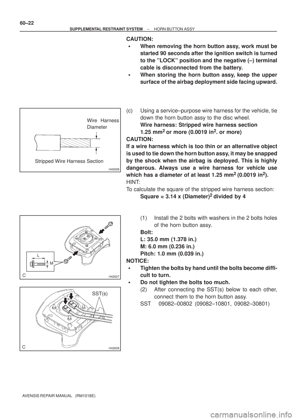
(c) Using a service±purpose wire harness for the vehicle, tie
down the horn button assy to the disc wheel.
Wire harness: Stripped wire harness section
1.25 mm
2
or more (0.0019 in2. or more)
CAUTION:
If a wire harness which is too thin or an alternative object
is used to tie down the horn button assy, it may be snapped
by the shock when the airbag is deployed. This is highly
dangerous. Always use a wire harness for vehicle use
which has a diameter of at least 1.25 mm
2
(0.0019 in2).
HINT:
To calculate the square of the stripped wire harness section:
Square = 3.14 x (Diameter)
2
divided by 4
(1) Install the 2 bolts with washers in the 2 bolts holes
of the horn button assy.
Bolt:
L: 35.0 mm (1.378 in.)
M: 6.0 mm (0.236 in.)
Pitch: 1.0 mm (0.039 in.)
NOTICE:
�Tighten the bolts by hand until the bolts become diffi-
cult to turn.
�Do not tighten the bolts too much.
(2) After connecting the SST(s) below to each other,
connect them to the horn button assy.
SST 09082±00802 (09082±10801, 09082±30801)
Page 2976 of 5135
H42629
2 Times or more
H42630SST(s)
H42631
SST(s)
± SUPPLEMENTAL RESTRAINT SYSTEMHORN BUTTON ASSY
60±23
AVENSIS REPAIR MANUAL (RM1018E)
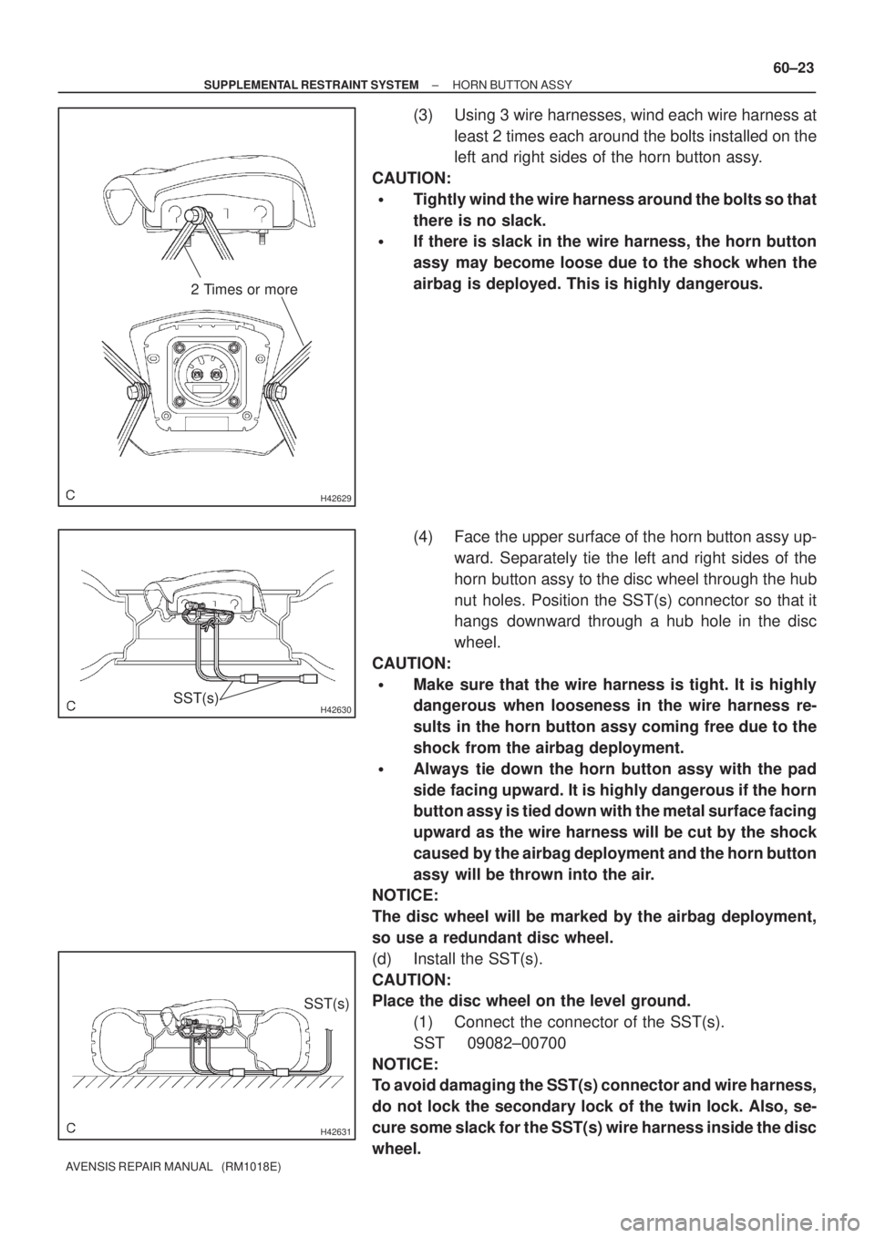
(3) Using 3 wire harnesses, wind each wire harness at
least 2 times each around the bolts installed on the
left and right sides of the horn button assy.
CAUTION:
�Tightly wind the wire harness around the bolts so that
there is no slack.
�If there is slack in the wire harness, the horn button
assy may become loose due to the shock when the
airbag is deployed. This is highly dangerous.
(4) Face the upper surface of the horn button assy up-
ward. Separately tie the left and right sides of the
horn button assy to the disc wheel through the hub
nut holes. Position the SST(s) connector so that it
hangs downward through a hub hole in the disc
wheel.
CAUTION:
�Make sure that the wire harness is tight. It is highly
dangerous when looseness in the wire harness re-
sults in the horn button assy coming free due to the
shock from the airbag deployment.
�Always tie down the horn button assy with the pad
side facing upward. It is highly dangerous if the horn
button assy is tied down with the metal surface facing
upward as the wire harness will be cut by the shock
caused by the airbag deployment and the horn button
assy will be thrown into the air.
NOTICE:
The disc wheel will be marked by the airbag deployment,
so use a redundant disc wheel.
(d) Install the SST(s).
CAUTION:
Place the disc wheel on the level ground.
(1) Connect the connector of the SST(s).
SST 09082±00700
NOTICE:
To avoid damaging the SST(s) connector and wire harness,
do not lock the secondary lock of the twin lock. Also, se-
cure some slack for the SST(s) wire harness inside the disc
wheel.
Page 4639 of 5135
141NI−01
A61175
A84394
A61184
14 −138
−
ENGINE MECHANICAL TIMING BELT (1CD−FTV)(From September, 2003)
AVENSIS Supplement (RM1045E)
REPLACEMENT
1. REMOVE FRONT WHEEL RH
2. REMOVE ENGINE UNDER COVER SUB −ASSY NO.1
3. REMOVE ENGINE UNDER COVER RH
4. REMOVE RADIATOR SUPPORT OPENING COVER
5. REMOVE ENGINE ROOM COVER SIDE
6. REMOVE ENGINE COVER SUB −ASSY NO.1 (See page 14 −90)
7. REMOVE INJECTOR DRIVER (See page 14 −108)
8. REMOVE V (COOLER COMPRESSOR TO CRANKSHAFT PULLEY) BELT NO.1 (See Pub. No. RM1018E on page 14 −269)
9. REMOVE GENERATOR V BELT (See Pub. No. RM1018E on page 14 −269)
10. SEPARATE PO W ER STEERI NG I DLE PULLEY BRACKET
(a) Remove the 3 bolts and power steering idle pulley brack- et.
11. DISCONNECT ENGINE WIRE
(a) Disconnect the 2 exhaust gas temperature sensor con- nectors.
12. DISCONNECT VACUUM HOSE (See page 14 −108)
13. REMOVE ENGINE MOUNTING INSULATOR SUB−ASSY RH
(a) Place a wooden block on a jack underneath the engine.
Page 4646 of 5135
A09602
Seal
Packing
Gasket
Groove
A61186
SST
−
ENGINE MECHANICAL TIMING BELT (1CD−FTV)(From September, 2003)
14 −145
AVENSIS Supplement (RM1045E)
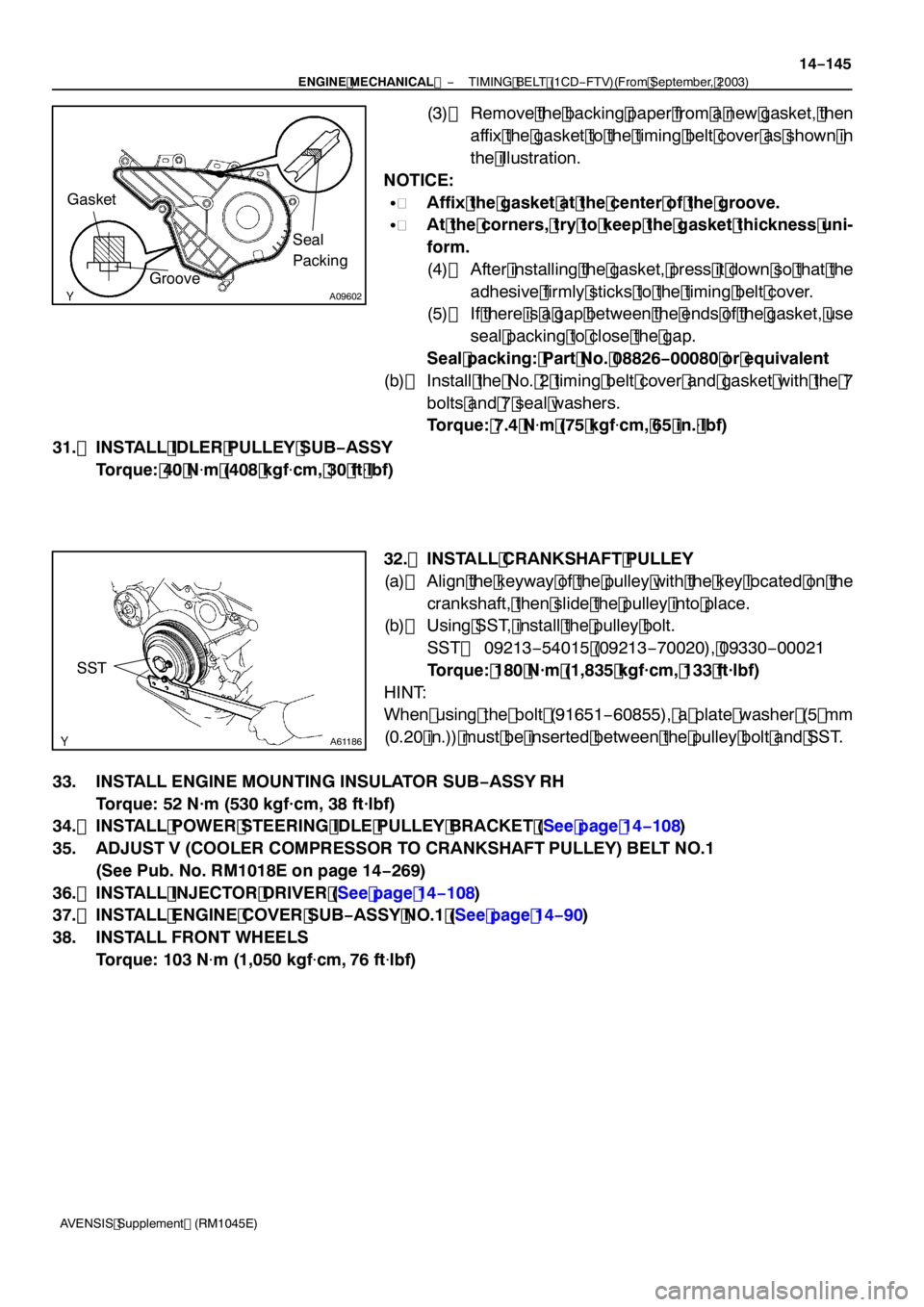
(3) Remove the backing paper from a new gasket, then
affix the gasket to the timing belt cover as shown in
the illustration.
NOTICE:
S Affix the gasket at the center of the groove.
S At the corners, try to keep the gasket thickness uni-
form.
(4) After installing the gasket, press it down so that the
adhesive firmly sticks to the timing belt cover.
(5) If there is a gap between the ends of the gasket, use
seal packing to close the gap.
Seal packing: Part No. 08826 −00080 or equivalent
(b) Install the No. 2 timing belt cover and gasket with the 7
bolts and 7 seal washers.
Torque: 7.4 N �m (75 kgf �cm, 65 in. �lbf)
31. INSTALL IDLER PULLEY SUB −ASSY
Torque: 40 N �m (408 kgf �cm, 30 ft �lbf)
32. INSTALL CRANKSHAFT PULLEY
(a) Align the keyway of the pulley with the key located on the crankshaft, then slide the pulley into place.
(b) Using SST, install the pulley bolt.
SST 09213 −54015 (09213 −70020), 09330 −00021
Torque: 180 N·m (1,835 kgf·cm, 133 ft·lbf)
HINT:
When using the bolt (91651 −60855), a plate washer (5 mm
(0.20 in.)) must be inserted between the pulley bolt and SST.
33. INSTALL ENGINE MOUNTING INSULATOR SUB −ASSY RH
Torque: 52 N·m (530 kgf·cm, 38 ft·lbf)
34. INSTALL POWER STEERING IDLE PULLEY BRACKET (See page 14 −108)
35. ADJUST V (COOLER COMPRESSOR TO CRANKSHAFT PULLEY) BELT NO.1 (See Pub. No. RM1018E on page 14 −269)
36. INSTALL INJECTOR DRIVER (See page 14 −108)
37. INSTALL ENGINE COVER SUB −ASSY NO.1 (See page 14 −90)
38. INSTALL FRONT WHEELS Torque: 103 N �m (1,050 kgf �cm, 76 ft �lbf)
Page 4649 of 5135
141NG−01
A84393
(a)
(a)
(b)(b)
(a)
A84286
14 −108−
ENGINE MECHANICAL PARTIAL ENGINE ASSY (1CD −FTV)(From September,
2003)
AVENSIS Supplement (RM1045E)
REPLACEMENT
1. REMOVE FRONT WHEELS
2. REMOVE ENGINE UNDER COVER LH
3. REMOVE ENGINE UNDER COVER SUB −ASSY NO.1
4. REMOVE ENGINE UNDER COVER RH
5. REMOVE RADIATOR SUPPORT OPENING COVER
6. REMOVE ENGINE ROOM COVER SIDE
7. DRAIN ENGINE COOLANT (See page 16 −19)
8. DRAIN ENGINE OIL (See Pub No. RM1018E on page 17 −30)
9. DRAIN MANUAL TRANSAXLE OIL
Torque: 49 N �m (500 kgf �cm, 36 ft �lbf)
10. REMOVE ENGINE COVER SUB −ASSY NO.1
(a) Remove the 5 nuts, then remove the engine cover.
11. REMOVE BATTERY
12. REMOVE AIR CLEANER ASSY
(a) Disconnect the mass air flow meter connector.
(b) Remove the air cleaner cap together with the air cleaner hose.
(c) Remove the air cleaner filter element.
(d) Remove the 3 bolts and air cleaner case.
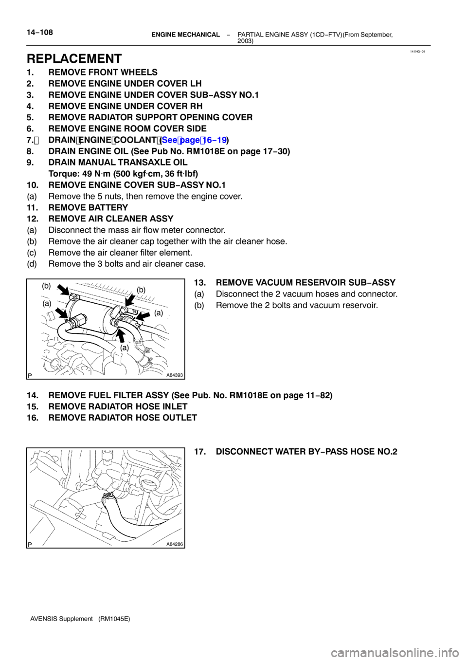
13. REMOVE VACUUM RESERVOIR SUB −ASSY
(a) Disconnect the 2 vacuum hoses and connector.
(b) Remove the 2 bolts and vacuum reservoir.
14. REMOVE FUEL FILTER ASSY (See Pub. No. RM1018E on page 11 −82)
15. REMOVE RADIATOR HOSE INLET
16. REMOVE RADIATOR HOSE OUTLET
17. DISCONNECT WATER BY−PASS HOSE NO.2
Page 4655 of 5135
A61186
SST
A84289
14−11 4−
ENGINE MECHANICAL PARTIAL ENGINE ASSY (1CD −FTV)(From September,
2003)
AVENSIS Supplement (RM1045E)
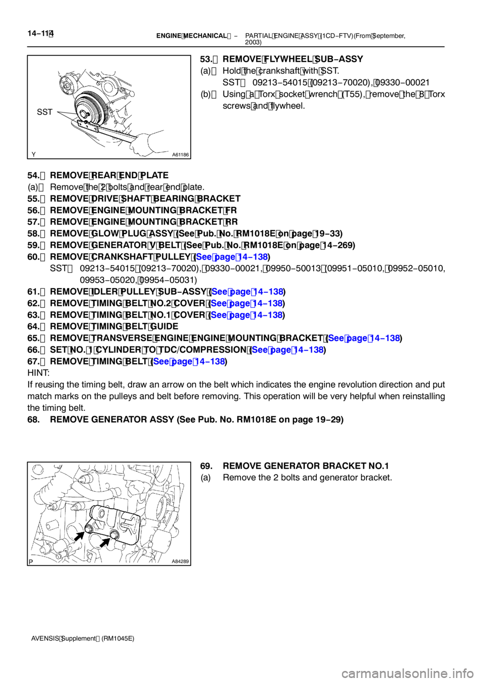
53. REMOVE FLYWHEEL SUB −ASSY
(a) Hold the crankshaft with SST. SST 09213 −54015 (09213 −70020), 09330 −00021
(b) Using a Torx socket wrench (T55), remove the 8 Torx
screws and flywheel.
54. REMOVE REAR END PLATE
(a) Remove the 2 bolts and rear end plate.
55. REMOVE DRIVE SHAFT BEARING BRACKET
56. REMOVE ENGINE MOUNTING BRACKET FR
57. REMOVE ENGINE MOUNTING BRACKET RR
58. REMOVE GLOW PLUG ASSY (See Pub. No. RM1018E on page 19 −33)
59. REMOVE GENERATOR V BELT (See Pub. No. RM1018E on page 14 −269)
60. REMOVE CRANKSHAFT PULLEY (See page 14 −138)
SST 09213 −54015 (09213 −70020), 09330 −00021, 09950 −50013 (09951 −05010, 09952 −05010,
09953 −05020, 09954 −05031)
61. REMOVE IDLER PULLEY SUB −ASSY (See page 14 −138)
62. REMOVE TIMING BELT NO.2 COVER (See page 14 −138)
63. REMOVE TIMING BELT NO.1 COVER (See page 14 −138)
64. REMOVE TIMING BELT GUIDE
65. REMOVE TRANSVERSE ENGINE ENGINE MOUNTING BRACKET (See page 14 −138)
66. SET NO. 1 CYLINDER TO TDC/COMPRESSION (See page 14 −138)
67. REMOVE TIMING BELT (See page 14 −138)
HINT:
If reusing the timing belt, draw an arrow on the belt which indicates the engine revolution direction and put
match marks on the pulleys and belt before removing. This operation will be very helpful when reinstalling
the timing belt.
68. REMOVE GENERATOR ASSY (See Pub. No. RM1018E on page 19 −29)
69. REMOVE GENERATOR BRACKET NO.1
(a) Remove the 2 bolts and generator bracket.