Page 214 of 687

Downloaded from www.Manualslib.com manuals search engine FRONT SUSPENSION 3D-41
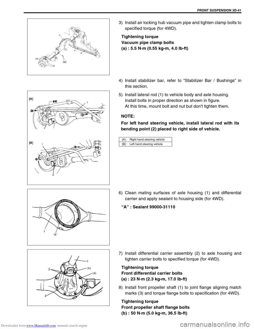
3) Install air locking hub vacuum pipe and tighten clamp bolts to
specified torque (for 4WD).
Tightening torque
Vacuum pipe clamp bolts
(a) : 5.5 N·m (0.55 kg-m, 4.0 lb-ft)
4) Install stabilizer bar, refer to “Stabilizer Bar / Bushings” in
this section.
5) Install lateral rod (1) to vehicle body and axle housing.
Install bolts in proper direction as shown in figure.
At this time, mount bolt and nut but don't tighten them.
6) Clean mating surfaces of axle housing (1) and differential
carrier and apply sealant to housing side (for 4WD).
“A” : Sealant 99000-31110
7) Install differential carrier assembly (2) to axle housing and
tighten carrier bolts to specified torque (for 4WD).
Tightening torque
Front differential carrier bolts
(a) : 23 N·m (2.3 kg-m, 17.0 lb-ft)
8) Install front propeller shaft (1) to joint flange aligning match
marks (3) and torque flange bolts to specification (for 4WD).
Tightening torque
Front propeller shaft flange bolts
(b) : 50 N·m (5.0 kg-m, 36.5 lb-ft)
NOTE:
For left hand steering vehicle, install lateral rod with its
bending point (2) placed to right side of vehicle.
[A] : Right hand steering vehicle
[B] : Left hand steering vehicle
Page 215 of 687

Downloaded from www.Manualslib.com manuals search engine 3D-42 FRONT SUSPENSION
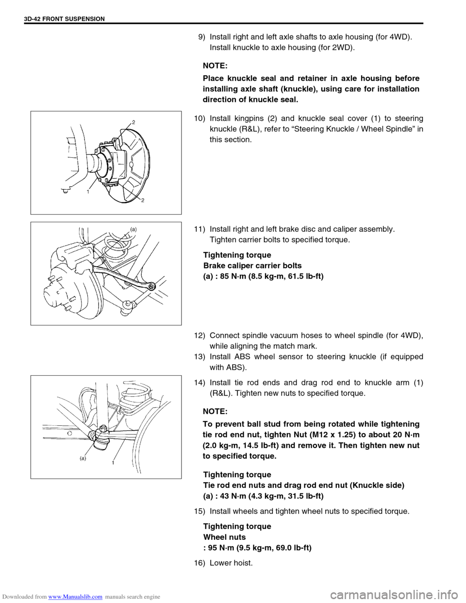
9) Install right and left axle shafts to axle housing (for 4WD).
Install knuckle to axle housing (for 2WD).
10) Install kingpins (2) and knuckle seal cover (1) to steering
knuckle (R&L), refer to “Steering Knuckle / Wheel Spindle” in
this section.
11) Install right and left brake disc and caliper assembly.
Tighten carrier bolts to specified torque.
Tightening torque
Brake caliper carrier bolts
(a) : 85 N·m (8.5 kg-m, 61.5 lb-ft)
12) Connect spindle vacuum hoses to wheel spindle (for 4WD),
while aligning the match mark.
13) Install ABS wheel sensor to steering knuckle (if equipped
with ABS).
14) Install tie rod ends and drag rod end to knuckle arm (1)
(R&L). Tighten new nuts to specified torque.
Tightening torque
Tie rod end nuts and drag rod end nut (Knuckle side)
(a) : 43 N·m (4.3 kg-m, 31.5 lb-ft)
15) Install wheels and tighten wheel nuts to specified torque.
Tightening torque
Wheel nuts
: 95 N·m (9.5 kg-m, 69.0 lb-ft)
16) Lower hoist.NOTE:
Place knuckle seal and retainer in axle housing before
installing axle shaft (knuckle), using care for installation
direction of knuckle seal.
NOTE:
To prevent ball stud from being rotated while tightening
tie rod end nut, tighten Nut (M12 x 1.25) to about 20 N·m
(2.0 kg-m, 14.5 Ib-ft) and remove it. Then tighten new nut
to specified torque.
Page 217 of 687

Downloaded from www.Manualslib.com manuals search engine 3D-44 FRONT SUSPENSION
Tightening Torque Specifications
Required Service Material
Fastening partTightening torque
Nm kg-m lb-ft
Stabilizer mount bracket bolt 20 2.0 14.5
Stabilizer ball joint nut 50 5.0 36.5
Shock absorber lock nut 29 2.9 21.0
Shock absorber lower nut 90 9.0 65.0
Brake caliper carrier bolt 85 8.5 61.5
Wheel bearing lock nut 220 22.0 160.0
Wheel bearing lock washer screw 1.5 0.15 1.0
Air locking hub bolt 48 4.8 35.0
Wheel spindle bolt 50 5.0 36.5
Kingpin bolt 25 2.5 18.0
Knuckle seal cover bolt 10 1.0 7.5
Tie-rod end nut
43 4.3 31.5
Drag-rod end nut (Knuckle side)
Lateral rod bolt and nut
90 9.0 65.0
Leading arm nut
Front differential carrier bolt 23 2.3 17.0
Front propeller shaft flange bolt 50 5.0 36.5
Wheel nut 95 9.5 69.0
Vacuum pipe clamp bolt 5.5 0.55 4.0
MaterialRecommended SUZUKI product
(Part Number)Use
Lithium grease SUZUKI SUPER GREASE (A)
(99000-25010)Knuckle seal / axle shaft oil seal
Recess of wheel spindles
Wheel hub oil seal
Wheel bearing
Spindle thrust washer
Spindle bush (inside and flange
part)
Spindle oil seal
SUZUKI SUPER GREASE (C)
(99000-25030)Kingpin bearing
Axle shaft joint (for 4WD)
Sealant SUZUKI BOND NO. 1215
(99000-31110)Mating surfaces of wheel spindle
and knuckle
Mating surface of differential carrier
and axle housing
Sealing compound SUZUKI SEALING COMPOUND
366E
(99000-31090)Mating surface of wheel spindle and
knuckle
Kingpin
Mating surfaces of hub cap and
wheel hub
Page 320 of 687

Downloaded from www.Manualslib.com manuals search engine ANTILOCK BRAKE SYSTEM (ABS) 5E-3
System Schematic
1. Wheel speed sensor (Right front) 7. Wheel speed sensor (Left rear) 13. ABS hydraulic unit
2. Stop lamp switch 8.“ABS” warning lamp 14. G sensor
3. ABS control module 9. ABS pump motor transistor 15. Data link connector
4. Wheel speed sensor (Right rear) 10. ABS solenoid valve transistor 16. ABS hydraulic unit / control module assembly
5. Monitor connector 11. Proportioning valve 17. 4WD switch (for 4WD model only)
6. ABS lamp driver module 12. Wheel speed sensor (Left front)
INPUTOUTPUT
ABS control
module Wheel speed sensor (RF)
Wheel speed sensor (RR)
Wheel speed sensor (LR)
Wheel speed sensor (LF)
Stop lamp switch
Diag. switch terminal
Battery voltage
4WD switch (for 4WD model only) G sensor
Pump motor
transistor
Fail-safe
transistor
Pump motor
LF hold solenoid
LF release solenoid
RF hold solenoid
RF release solenoid
Rear hold solenoid
Rear release solenoid
“ABS” warning lamp
Idle-up
ECM
Data link connector
ABS hydraulic unit/control
module assembly
Page 328 of 687
Downloaded from www.Manualslib.com manuals search engine ANTILOCK BRAKE SYSTEM (ABS) 5E-11
Diagnostic Trouble Code (DTC) Table
DTC
(displayed on
SUZUKI scan
tool)DTC
(indicated by
ABS warn-
ing lamp)ABS warning light flashing
patternDIAGNOSTIC ITEMS
–12 Normal
C1015 15 G sensor circuit (for 4WD model only)
C1016 16 Stop lamp switch circuit
C1021 21 RF
Wheel speed sensor circuit and/or sen-
sor ring C1025 25 LF
C1031 31 RR
C1035 35 LR
C1022 22 RF
C1026 26 LF
C1032 32 RR
C1036 36 LR
C1041 41
RFHold solenoid valve circuit
C1042 42 Release solenoid valve circuit
C1045 45
LFHold solenoid valve circuit
C1046 46 Release solenoid valve circuit
C1055 55
RearHold solenoid valve circuit
C1056 56 Release solenoid valve circuit
Page 329 of 687

Downloaded from www.Manualslib.com manuals search engine 5E-12 ANTILOCK BRAKE SYSTEM (ABS)
System Circuit
C1057 57 Power source
C1061 61 ABS pump motor circuit
C1063 63 ABS solenoid valve circuit
C1071 71 ABS control module
1. Battery 5-5. Solenoid valves 14. Stop lamp switch
2. Main fuses 6. Combination meter 15. ECM
3. Ignition switch 7. Right rear wheel speed sensor 16. G sensor
4. Circuit fuses 8. Left rear wheel speed sensor 17. 4WD switch (for 4WD model only)
5. ABS hydraulic unit / control module assem-
bly9. Right front wheel speed sensor 18. 4WD indicator lamp (for 4WD model only)
5-1. Terminal arrangement for ABS hydraulic unit
/ control module assembly10. Left front wheel speed sensor 19. 4WD controller (for 4WD model only)
5-2. ABS fail-safe transistor 11. Data link connector 20.“ABS” warning lamp
5-3. ABS pump motor transistor 12. Monitor connector 21. ABS lamp driver module
5-4. Pump motor 13. Stop lamp
DTC
(displayed on
SUZUKI scan
tool)DTC
(indicated by
ABS warn-
ing lamp)ABS warning light flashing
patternDIAGNOSTIC ITEMS
Page 330 of 687

Downloaded from www.Manualslib.com manuals search engine ANTILOCK BRAKE SYSTEM (ABS) 5E-13
TERMINAL CIRCUIT
A1 Idle up signal
A2 Stop lamp switch
A3 Right front wheel speed sensor (+)
A4 Right front wheel speed sensor (–)
A5–
A6 Right rear wheel speed sensor (–)
A7 Right rear wheel speed sensor (+)
A8–
A9–
A10–
A11 G sensor signal
A12 Diagnosis switch terminal
A13 G sensor ground
A14“ABS” warning lamp
A15 Left front wheel speed sensor (+)
A16 Left front wheel speed sensor (–)
A17 4WD switch (for 4WD model only)
A18 Ignition switch
A19 Left rear wheel speed sensor (+)
A20 Left rear wheel speed sensor (–)
A21 Data link connector
A22 Ground (for ABS pump motor)
A23 ABS pump motor power supply
A24 Ground (for ABS control module)
A25 Solenoid valve power supply
Wire color
B : Black G/W : Green / White R/W : Red / White
B/BI : Black / Blue Lg/B : Light green / Black W/Bl : White / Blue
B/W : Black / White Lg/R : Light green / Red W/G : White / Green
B/Or : Black / Orange Or : Orange W/R : White / Red
Bl : Blue Or/B : Orange / Black Y : Yellow
Bl/W : Blue / White P/B : Pink / Black Y/B : Yellow / Black
G : Green P/G : Pink / Green
G/B : Green / Black R/Bl : Red / Blue
Page 615 of 687

Downloaded from www.Manualslib.com manuals search engine 6E-10 ENGINE AND EMISSION CONTROL SYSTEM
1. CKP sensor 20. Power steering pressure switch
(if equipped)39. Ignition coil assembly (for No.1 and No.4 spark plugs)
2. CMP sensor 21. A/C switch 40. Ignition coil assembly (for No.2 and No.3 spark plugs)
3. VSS 22. A/C refrigerant pressure switch
(if equipped)41. Stop lamp switch
4. MAP sensor 23. Immobilizer control module (if equipped) 42. Stop lamp
5. Knock sensor 24. Data link connector 43. Lighting switch
6. TP sensor 25. Injector No.1 44. Position lamp
7. ECT sensor 26. Injector No.2 45. Rear defogger switch (if equipped)
8. IAT sensor 27. Injector No.3 46. Rear defogger (if equipped)
9. Heated oxygen sensor-1 (if equipped) 28. Injector No.4 47. A/C compressor clutch (if equipped)
10. Heated oxygen sensor-2 (if equipped) 29. IAC valve 48. Ignition switch
11. A/C evaporator temp. sensor (if equipped) 30. EVAP canister purge valve 49. Main relay
12. Speedometer 31. Fuel pump relay 50. CO adjusting register (if equipped)
13. Fuel level sensor 32. Fuel pump 51. Starting motor
14. TCM (A/T) 33. A/C condenser fan relay (if equipped) 52. 4WD controller (4WD)
15. Transmission range switch (A/T) 34. A/C condenser fan motor (if equipped) 53. ABS control module (if equipped)
16. Shift lock solenoid (A/T, if equipped) 35. EGR valve (if equipped) 54. Engine ground
17. Backup lamp 36. Malfunction indicator lamp 55. Body ground
18. Heater fan motor 37. Immobilizer indicator lamp (if equipped)
19. Heater fan switch 38. Monitor connector (vehicle without immo-
bilizer indicator lamp)