Page 184 of 687

Downloaded from www.Manualslib.com manuals search engine FRONT SUSPENSION 3D-11
4WD Control System Check
AIR LOCKING HUB
1) Start engine and shift transfer shift control lever to 2H posi-
tion.
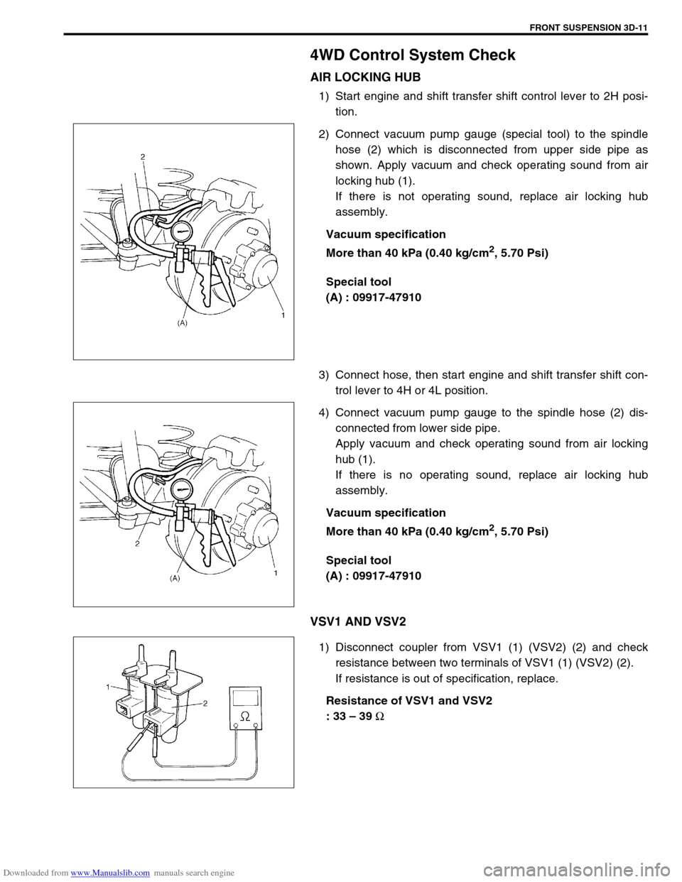
2) Connect vacuum pump gauge (special tool) to the spindle
hose (2) which is disconnected from upper side pipe as
shown. Apply vacuum and check operating sound from air
locking hub (1).
If there is not operating sound, replace air locking hub
assembly.
Vacuum specification
More than 40 kPa (0.40 kg/cm
2, 5.70 Psi)
Special tool
(A) : 09917-47910
3) Connect hose, then start engine and shift transfer shift con-
trol lever to 4H or 4L position.
4) Connect vacuum pump gauge to the spindle hose (2) dis-
connected from lower side pipe.
Apply vacuum and check operating sound from air locking
hub (1).
If there is no operating sound, replace air locking hub
assembly.
Vacuum specification
More than 40 kPa (0.40 kg/cm
2, 5.70 Psi)
Special tool
(A) : 09917-47910
VSV1 AND VSV2
1) Disconnect coupler from VSV1 (1) (VSV2) (2) and check
resistance between two terminals of VSV1 (1) (VSV2) (2).
If resistance is out of specification, replace.
Resistance of VSV1 and VSV2
: 33 – 39
Ω
Page 185 of 687
Downloaded from www.Manualslib.com manuals search engine 3D-12 FRONT SUSPENSION
2) Blow air from B and check that air comes out of C.
If found faulty, replace.
3) Connect 12 V-battery to VSV1 (VSV2) terminals and check
continuity between A and B.
Blow air from B and check that air comes out of A.
If found faulty, replace.
VACUUM SWITCH
1) Disconnect coupler from vacuum switch and check resis-
tance between two terminals of vacuum switch.
If resistance is out of specification, replace.
Resistance of vacuum switch
: More than 1 M
Ω
2) Connect vacuum pump gauge and apply vacuum more than
40 kPa (0.40 kg/cm
2, 5.70 Psi), then check resistance
between terminals of vacuum switch.
If resistance is out of specification, replace.
Vacuum switch resistance
: Less than 0.8
Ω
Special tool
(A) : 09917-47910
4WD SWITCH
Refer to “4WD Switch” in Section 7D.
VACUUM HOSE / PIPE
Inspect vacuum hoses for leaks or cracks, vacuum pipes for
cracks, dents or corrosion. If defective, replace.
Page 195 of 687
Downloaded from www.Manualslib.com manuals search engine 3D-22 FRONT SUSPENSION
4) Remove brake disc.
5) Remove front wheel bearing lock nut as follows.
For 2WD model :
a) Remove hub cap.
b) Remove front wheel bearing lock plate (1) by loosening 4
screws (2).
For 4WD model :
a) Remove air locking hub assembly (1).
b) Remove front axle shaft circlip and wheel spindle thrust
washer.
c) Uncaulk front wheel bearing lock nut. NOTE:
If brake disc can not be removed by hand, using 8 mm
bolts.
1. Wheel hub
Page 196 of 687
Downloaded from www.Manualslib.com manuals search engine FRONT SUSPENSION 3D-23
6) Remove front wheel bearing lock nut by using special tool.
Special tool
(A) : 09944-77020 (For 4WD)
(A) : 09951-16050 (For 2WD)
7) Remove front wheel bearing washer.
8) Remove wheel hub complete (1) with bearings (2) and oil
seal (4).
Special tool
(A) : 09943-35511 or 09943-35512
(B) : 09942-15510
9) Remove sensor rotor from wheel hub as shown (if equipped
with ABS).
10) Remove wheel bearing oil seal and circlip.
3. Circlip
NOTE:
If wheel hub can not be removed by hand, use special
tools as shown.
CAUTION:
Pull out sensor rotor from wheel hub gradually and
evenly.
Attempt to pull it out partially may cause it to be
deformed.
1. Sensor rotor
2. Wheel hub
3. Vise
4. Flat end rod
Page 198 of 687

Downloaded from www.Manualslib.com manuals search engine FRONT SUSPENSION 3D-25
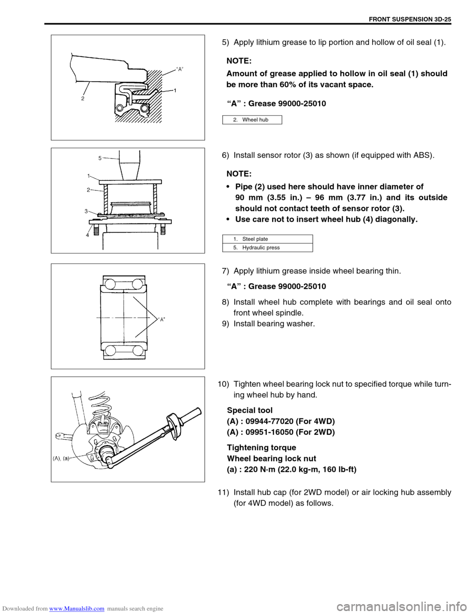
5) Apply lithium grease to lip portion and hollow of oil seal (1).
“A” : Grease 99000-25010
6) Install sensor rotor (3) as shown (if equipped with ABS).
7) Apply lithium grease inside wheel bearing thin.
“A” : Grease 99000-25010
8) Install wheel hub complete with bearings and oil seal onto
front wheel spindle.
9) Install bearing washer.
10) Tighten wheel bearing lock nut to specified torque while turn-
ing wheel hub by hand.
Special tool
(A) : 09944-77020 (For 4WD)
(A) : 09951-16050 (For 2WD)
Tightening torque
Wheel bearing lock nut
(a) : 220 N·m (22.0 kg-m, 160 lb-ft)
11) Install hub cap (for 2WD model) or air locking hub assembly
(for 4WD model) as follows. NOTE:
Amount of grease applied to hollow in oil seal (1) should
be more than 60% of its vacant space.
2. Wheel hub
NOTE:
Pipe (2) used here should have inner diameter of
90 mm (3.55 in.) – 96 mm (3.77 in.) and its outside
should not contact teeth of sensor rotor (3).
Use care not to insert wheel hub (4) diagonally.
1. Steel plate
5. Hydraulic press
Page 199 of 687

Downloaded from www.Manualslib.com manuals search engine 3D-26 FRONT SUSPENSION
For 2WD model:
a) Using lock plate (1), lock bearing lock nut. If lock screw hole
is not aligned with screw hole in lock nut, turn lock nut in
tightening direction till they align.
Tightening torque
Wheel bearing lock washer screw
(a) : 1.5 N·m (0.15 kg-m, 1.0 lb-ft)
b) Remove grease, old sealant and dusts from mating sur-
faces of hub cap (1) and wheel hub (2) to clean, apply
water tight sealant to hub cap mating surface evenly, and
install hub cap (1) to wheel hub (2).
“A” : Sealant 99000-31090
For 4WD model:
a) Caulk front wheel bearing lock nut at groove of spindle.
b) Apply lithium grease thinly to both surface, all around of
front spindle thrust washer (1).
“A” : Grease 99000-25010
NOTE:
When installing hub cap (1), hammer lightly several
locations on the collar of cap until collar comes closely
into contact with wheel hub (2).
If fitting part of cap is deformed or damaged or if it is
fitted loosely, replace with new one.
Page 200 of 687

Downloaded from www.Manualslib.com manuals search engine FRONT SUSPENSION 3D-27
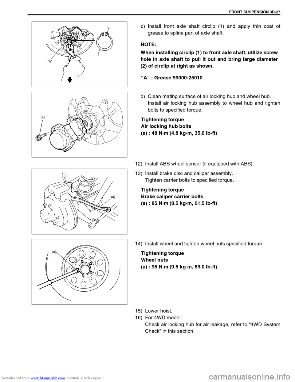
c) Install front axle shaft circlip (1) and apply thin coat of
grease to spline part of axle shaft.
“A” : Grease 99000-25010
d) Clean mating surface of air locking hub and wheel hub.
Install air locking hub assembly to wheel hub and tighten
bolts to specified torque.
Tightening torque
Air locking hub bolts
(a) : 48 N·m (4.8 kg-m, 35.0 lb-ft)
12) Install ABS wheel sensor (if equipped with ABS).
13) Install brake disc and caliper assembly.
Tighten carrier bolts to specified torque.
Tightening torque
Brake caliper carrier bolts
(a) : 85 N·m (8.5 kg-m, 61.5 lb-ft)
14) Install wheel and tighten wheel nuts specified torque.
Tightening torque
Wheel nuts
(a) : 95 N·m (9.5 kg-m, 69.0 lb-ft)
15) Lower hoist.
16) For 4WD model:
Check air locking hub for air leakage, refer to “4WD System
Check” in this section. NOTE:
When installing circlip (1) to front axle shaft, utilize screw
hole in axle shaft to pull it out and bring large diameter
(2) of circlip at right as shown.
Page 201 of 687
Downloaded from www.Manualslib.com manuals search engine 3D-28 FRONT SUSPENSION
Steering Knuckle / Wheel Spindle
REMOVAL
1) Hoist vehicle and remove wheel.
2) Remove wheel hub assembly, refer to “Wheel Hub / Bearing /
Oil Seal” in this section.
3) Disconnect spindle vacuum hoses (1) from wheel spindle (for
4WD).
4) Remove disc dust cover (1) and wheel spindle (2).
5) Remove tie rod end (and drag rod end) nut(s) and discon-
nect tie rod end (and drag rod end) (2) from steering knuckle
(1) with special tool.
Special tool
(A) : 09913-65210
6) Remove knuckle seal cover bolts. Then remove knuckle seal
cover (1), knuckle seal and knuckle seal retainer from
knuckle. CAUTION:
Give match mark to each spindle vacuum hoses before
removing hose.