CAMSHAFT
EM-59
[QR]
C
D
E
F
G
H
I
J
K
L
MA
EM
4. If out of the standard, replace camshaft.
Camshaft Cam Height
1. Measure the camshaft cam height with a micrometer.
2. If out of the standard, replace camshaft.
Camshaft Journal Oil Clearance
CAMSHAFT JOURNAL DIAMETER
Measure the outer diameter of camshaft journal with a micrometer.
CAMSHAFT BRACKET INNER DIAMETER
�Tighten camshaft bracket bolts with specified torque. Refer to EM-61, "INSTALLATION" for the tightening
procedure.
�Measure the inner diameter of camshaft bracket with an inside
micrometer.
CAMSHAFT JOURNAL OIL CLEARANCE
�(Oil clearance) = (Camshaft bracket inner diameter) – (Camshaft journal diameter)
�If out of the standard, replace either or both camshaft and cylinder head.
NOTE:
Camshaft bracket cannot be replaced as a single part, because it is machined together with cylinder head.
Replace whole cylinder head assembly.
Camshaft End Play
1. Install camshaft in cylinder head. Refer to EM-61, "INSTALLATION" for tightening procedure. Standard:
Intake
QR20DE : 45.015 - 45.205 mm (1.7722 - 1.7797 in)
QR25DE : 45.665 - 45.855 mm (1.7978 - 1.8053 in)
Exhaust
QR20DE : 42.825 - 43.015 mm (1.6860 - 1.6935 in)
QR25DE : 43.975 - 44.165 mm (1.7313 - 1.7388 in)
PBIC0039E
Standard:
No. 1 : 27.935 - 27.955 mm (1.0998 - 1.1006 in)
No. 2, 3, 4, 5 : 23.435 - 23.455 mm (0.9226 - 0.9234 in)
PBIC0040E
Standard:
No. 1 : 28.000 - 28.021 mm (1.1024 - 1.1032 in)
No. 2, 3, 4, 5 : 23.500 - 23.521 mm (0.9252 - 0.9260 in)
PBIC0041E
Standard: 0.045 - 0.086 mm (0.0018 - 0.0034 in)
CAMSHAFT
EM-61
[QR]
C
D
E
F
G
H
I
J
K
L
MA
EM
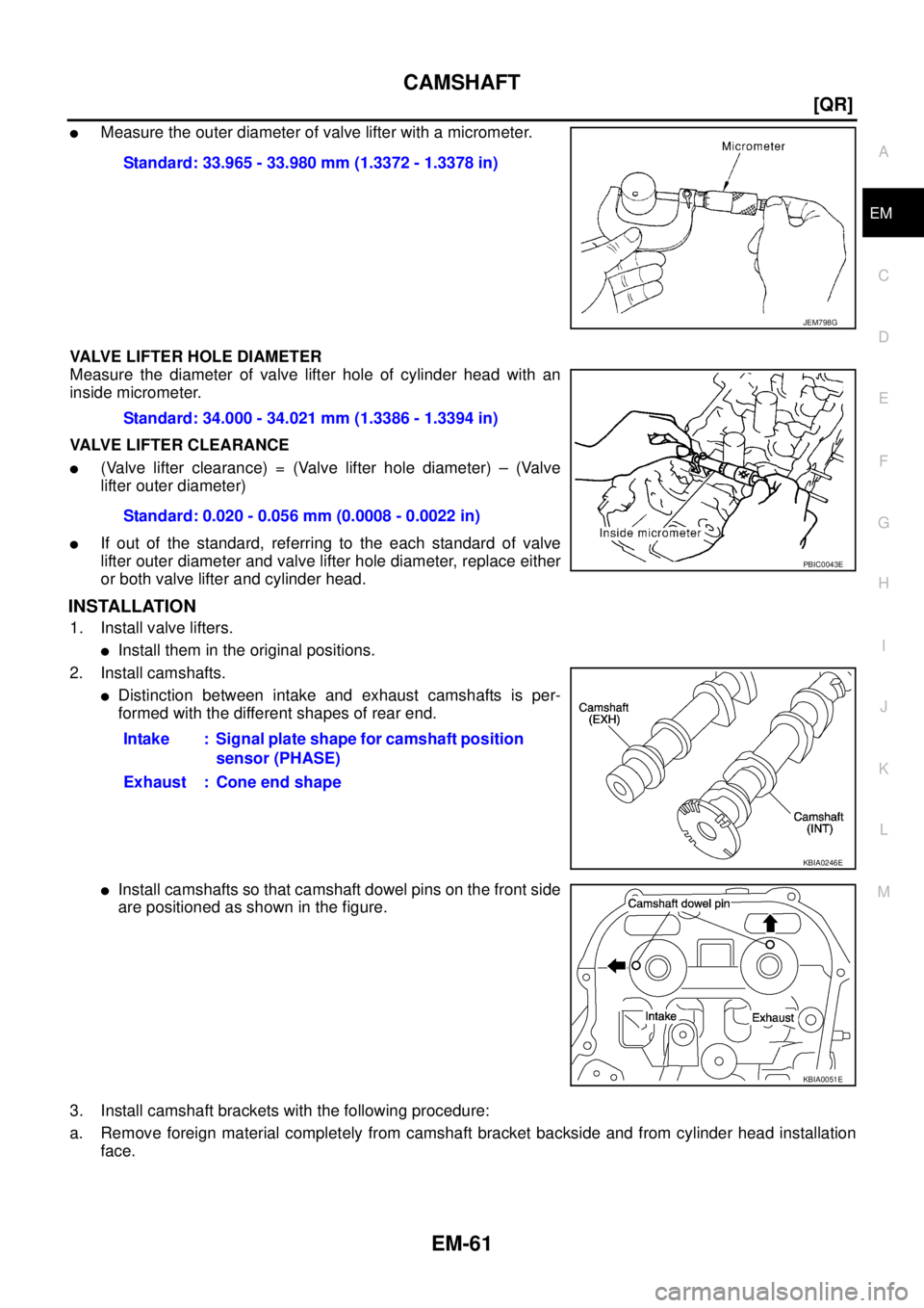
�Measure the outer diameter of valve lifter with a micrometer.
VALVE LIFTER HOLE DIAMETER
Measure the diameter of valve lifter hole of cylinder head with an
inside micrometer.
VALVE LIFTER CLEARANCE
�(Valve lifter clearance) = (Valve lifter hole diameter) – (Valve
lifter outer diameter)
�If out of the standard, referring to the each standard of valve
lifter outer diameter and valve lifter hole diameter, replace either
or both valve lifter and cylinder head.
INSTALLATION
1. Install valve lifters.
�Install them in the original positions.
2. Install camshafts.
�Distinction between intake and exhaust camshafts is per-
formed with the different shapes of rear end.
�Install camshafts so that camshaft dowel pins on the front side
are positioned as shown in the figure.
3. Install camshaft brackets with the following procedure:
a. Remove foreign material completely from camshaft bracket backside and from cylinder head installation
face.Standard: 33.965 - 33.980 mm (1.3372 - 1.3378 in)
JEM798G
Standard: 34.000 - 34.021 mm (1.3386 - 1.3394 in)
Standard: 0.020 - 0.056 mm (0.0008 - 0.0022 in)
PBIC0043E
Intake : Signal plate shape for camshaft position
sensor (PHASE)
Exhaust : Cone end shape
KBIA0246E
KBIA0051E
EM-66
[QR]
CAMSHAFT
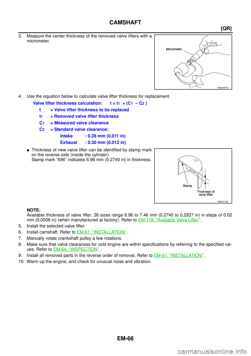
3. Measure the center thickness of the removed valve lifters with a
micrometer.
4. Use the equation below to calculate valve lifter thickness for replacement.
�Thickness of new valve lifter can be identified by stamp mark
on the reverse side (inside the cylinder).
Stamp mark “696” indicates 6.96 mm (0.2740 in) in thickness.
NOTE:
Available thickness of valve lifter: 26 sizes range 6.96 to 7.46 mm (0.2740 to 0.2937 in) in steps of 0.02
mm (0.0008 in) (when manufactured at factory). Refer to EM-119, "
Available Valve Lifter" .
5. Install the selected valve lifter.
6. Install camshaft. Refer to EM-61, "
INSTALLATION" .
7. Manually rotate crankshaft pulley a few rotations.
8. Make sure that valve clearances for cold engine are within specifications by referring to the specified val-
ues. Refer to EM-64, "
INSPECTION" .
9. Install all removed parts in the reverse order of removal. Refer to EM-61, "
INSTALLATION" .
10. Warm up the engine, and check for unusual noise and vibration.
KBIA0057E
Valve lifter thickness calculation: t = t1 + (C1 – C2 )
t = Valve lifter thickness to be replaced
t
1 = Removed valve lifter thickness
C
1= Measured valve clearance
C
2= Standard valve clearance:
Intake : 0.28 mm (0.011 in)
Exhaust : 0.30 mm (0.012 in)
KBIA0119E
![NISSAN X-TRAIL 2005 Service Repair Manual CAMSHAFT
EM-59
[QR]
C
D
E
F
G
H
I
J
K
L
MA
EM
4. If out of the standard, replace camshaft.
Camshaft Cam Height
1. Measure the camshaft cam height with a micrometer.
2. If out of the standard, replac](/manual-img/5/57403/w960_57403-112.png "NISSAN X-TRAIL 2005 Service Repair Manual CAMSHAFT
EM-59
[QR]
C
D
E
F
G
H
I
J
K
L
MA
EM
4. If out of the standard, replace camshaft.
Camshaft Cam Height
1. Measure the camshaft cam height with a micrometer.
2. If out of the standard, replac")