Page 3306 of 4555
ATC-128
INTAKE DOOR MOTOR
INTAKE DOOR MOTORPFP:27730
Removal and InstallationEJS004GL
REMOVAL
1. Remove blower unit. Refer to ATC-125, "BLOWER UNIT" .
2. Remove mounting screws, and then intake door motor from
blower unit.
INSTALLATION
Installation is basically the reverse order of removal.
RJIA0056E
RJIA0571E
Page 3307 of 4555
FAN CONTROL AMPLIFIER
ATC-129
C
D
E
F
G
H
I
K
L
MA
B
AT C
FAN CONTROL AMPLIFIERPFP:27761
Removal and InstallationEJS004GE
REMOVAL
1. Remove blower unit. Refer to ATC-125, "BLOWER UNIT" .
2. Remove mounting screws, and then remove fan control amp.
INSTALLATION
Installation is basically the reverse order of removal.
RJIA0572E
Page 3308 of 4555
ATC-130
AIR CONDITIONER FILTER
AIR CONDITIONER FILTERPFP:27277
Removal and InstallationEJS005RT
FUNCTION
Air inside passenger compartment is kept clean at either recircula-
tion or fresh mode by installing air conditioner filter into blower unit.
REPLACEMENT TIMING
Refer to MA-7, "Periodic Maintenance" .
Caution label is fixed inside the glove box.
REPLACEMENT PROCEDURES
1. Remove glove box. Refer to IP-11, "Removal and Installation" .
2. Remove filter cover.
3. Take out air conditioner filter from blower unit.
4. Replace with new one and reinstall on blower unit.
5. Reinstall glove box.
SJIA0446E
SJIA0447E
Page 3309 of 4555
HEATER & COOLING UNIT ASSEMBLY
ATC-131
C
D
E
F
G
H
I
K
L
MA
B
AT C
HEATER & COOLING UNIT ASSEMBLYPFP:27110
Removal and InstallationEJS000UT
REMOVAL
1. Use a refrigerant collecting equipment (for HFC-134a) to discharge refrigerant.
2. Drain coolant from cooling system. Refer to CO-9, "
Changing Engine Coolant" for QR engine or CO-32,
"Changing Engine Coolant" for YD engine.
3. Disconnect two heater hoses from heater core pipe.
4. Remove mounting bolt from low-pressure flexible hose.
CAUTION:
Cap or wrap the joint of the pipe with suitable material such
as vinyl tape to avoid the entry of air.
5. Remove the blower unit. Refer to ATC-125, "
BLOWER UNIT" .
6. Remove clips of vehicle harness from steering member.
7. Remove mounting nuts, and then remove instrument stay.
8. Remove mounting bolts from heater & cooling unit.
RJIA0060E
RJIA0061E
RJIA2444E
Page 3321 of 4555
REFRIGERANT LINES
ATC-143
C
D
E
F
G
H
I
K
L
MA
B
AT C
ComponentsEJS00287
Refer to page AT C - 5 , "Precautions for Refrigerant Connection" .
WITH GASOLINE ENGINE
NOTE:
This illustration is for RHD models. The blower unit and heater & cooling unit layouts for LHD models are sym-
metrically opposite.
RJIA2843E
Page 3322 of 4555
ATC-144
REFRIGERANT LINES
WITH DIESEL ENGINE
NOTE:
This illustration is for RHD models. The blower unit and heater & cooling unit layouts for LHD models are sym-
metrically opposite.
Removal and Installation of CompressorEJS000V9
REMOVAL
With Gasoline Engine
RJIA2844E
RJIA3185E
Page 3336 of 4555

ATC-158
REFRIGERANT LINES
Removal and Installation of Dual-pressure SwitchEJS00289
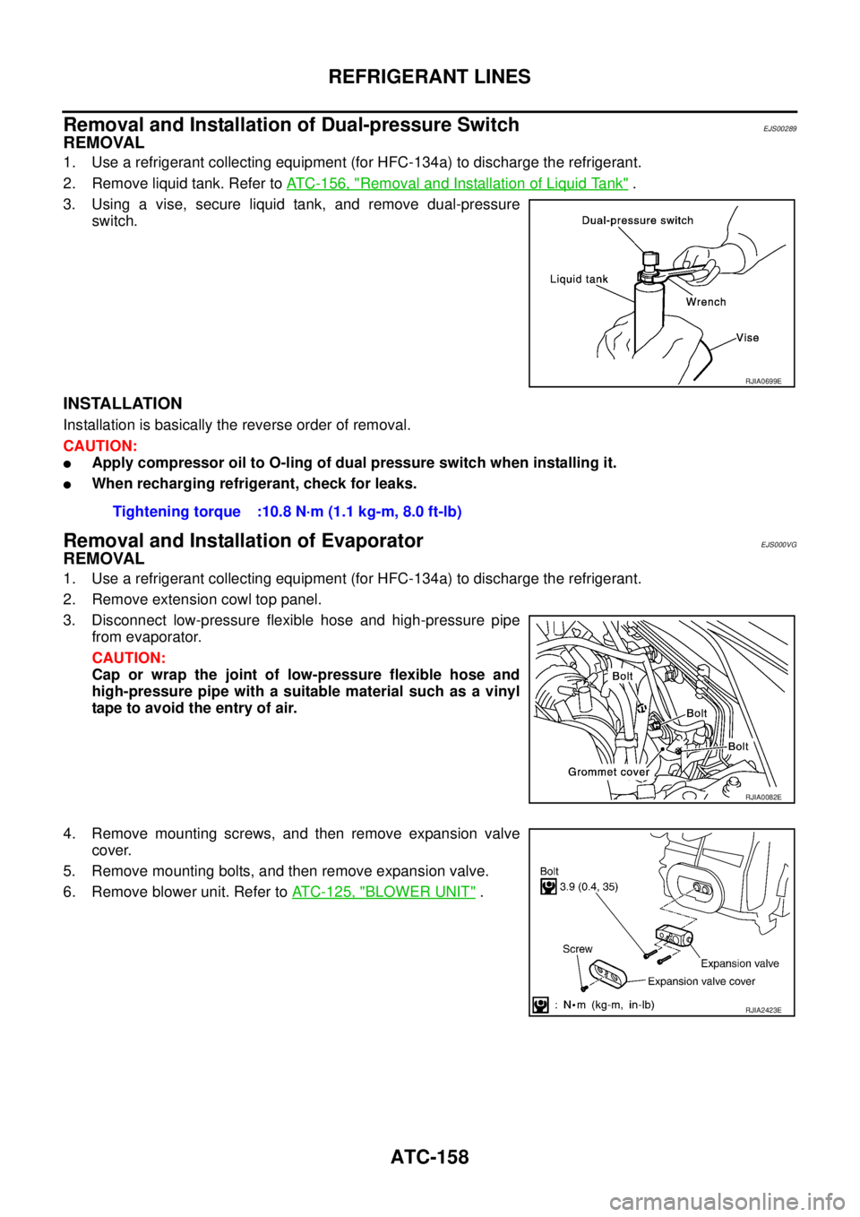
REMOVAL
1. Use a refrigerant collecting equipment (for HFC-134a) to discharge the refrigerant.
2. Remove liquid tank. Refer to ATC-156, "
Removal and Installation of Liquid Tank" .
3. Using a vise, secure liquid tank, and remove dual-pressure
switch.
INSTALLATION
Installation is basically the reverse order of removal.
CAUTION:
�Apply compressor oil to O-ling of dual pressure switch when installing it.
�When recharging refrigerant, check for leaks.
Removal and Installation of EvaporatorEJS000VG
REMOVAL
1. Use a refrigerant collecting equipment (for HFC-134a) to discharge the refrigerant.
2. Remove extension cowl top panel.
3. Disconnect low-pressure flexible hose and high-pressure pipe
from evaporator.
CAUTION:
Cap or wrap the joint of low-pressure flexible hose and
high-pressure pipe with a suitable material such as a vinyl
tape to avoid the entry of air.
4. Remove mounting screws, and then remove expansion valve
cover.
5. Remove mounting bolts, and then remove expansion valve.
6. Remove blower unit. Refer to ATC-125, "
BLOWER UNIT" .
RJIA0699E
Tightening torque :10.8 N·m (1.1 kg-m, 8.0 ft-lb)
RJIA0082E
RJIA2423E
Page 3340 of 4555

ATC-162
REFRIGERANT LINES
3. Check if the A/C refrigerant pressure is at least 345 kPa (3.45 bar, 3.52 kg/cm2 , 50 psi) above 16°C
(61°F). If less than specification, recover/evacuate and recharge the system with the specified amount of
refrigerant.
NOTE:
At temperatures below 16°C (61°F), leaks may not be detected since the system may not reach 345 kPa (3.45
bar, 3.52 kg/cm
2 , 50 psi).
4. Perform the leak test from the high-pressure side (compressor discharge a to evaporator inlet g) to the
low-pressure side (evaporator drain hose h to shaft seal k). Refer to ATC-143, "
Components" . Perform a
leak check for the following areas carefully. Clean the component to be checked and move the leak
detected probe completely around the connection/component.
Compressor
Check the fitting of high- and low- pressure hoses, relief valve and shaft seal.
Liquid tank
Check the refrigerant pressure sensor or dual pressure switch.
Service valves
Check all around the service valves. Ensure service valve caps are secured on the service valves (to pre-
vent leaks).
NOTE:
After removing A/C manifold gauge set from service valves, wipe any residue from valves to prevent any
false readings by leak detector.
Cooling unit (Evaporator)
With engine OFF, turn blower fan on “High” for at least 15 seconds to dissipate any refrigerant trace in the
cooling unit. Wait a minimum of 10 minutes accumulation time (refer to the manufacturer’s recommended
procedure for actual wait time) before inserting the leak detector probe into the drain hose.
Keep the probe inserted for at least 10 seconds. Use caution not to contaminate the probe tip with water
or dirt that may be in the drain hose.
5. If a leak detector detects a leak, verify at least once by blowing compressed air into area of suspected
leak, then repeat check as outlined above.
6. Do not stop when one leak is found. Continue to check for additional leaks at all system components.
If no leaks are found, perform steps 7-10.
7. Start engine.
8. Set the heater A/C control as follows;
a. A/C switch: ON
b. Mode control dial: VENT (Ventilation)
c. Intake position: Recirculation
d. Max. cold temperature
e. Fan speed: High
9. Run engine at 1,500 rpm for at least 2 minutes.
10. Turn engine off and perform leak check again following steps 4 through 6 above.
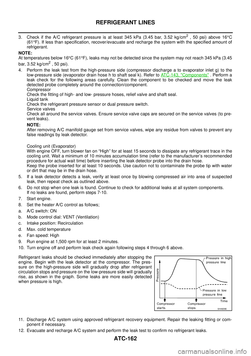
Refrigerant leaks should be checked immediately after stopping the
engine. Begin with the leak detector at the compressor. The pres-
sure on the high-pressure side will gradually drop after refrigerant
circulation stops and pressure on the low-pressure side will gradually
rise, as shown in the graph. Some leaks are more easily detected
when pressure is high.
11. Discharge A/C system using approved refrigerant recovery equipment. Repair the leaking fitting or com-
ponent if necessary.
12. Evacuate and recharge A/C system and perform the leak test to confirm no refrigerant leaks.
SHA839E