Page 3209 of 4555
AIR CONDITIONER CONTROL
ATC-31
C
D
E
F
G
H
I
K
L
MA
B
AT C
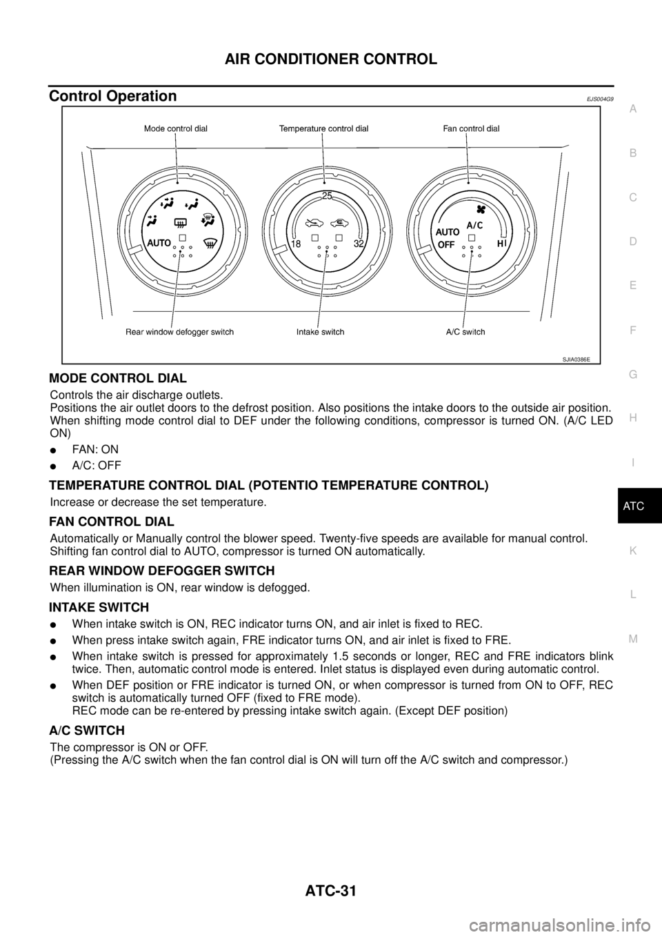
Control OperationEJS004G9
MODE CONTROL DIAL
Controls the air discharge outlets.
Positions the air outlet doors to the defrost position. Also positions the intake doors to the outside air position.
When shifting mode control dial to DEF under the following conditions, compressor is turned ON. (A/C LED
ON)
�FAN: O N
�A/C: OFF
TEMPERATURE CONTROL DIAL (POTENTIO TEMPERATURE CONTROL)
Increase or decrease the set temperature.
FAN CONTROL DIAL
Automatically or Manually control the blower speed. Twenty-five speeds are available for manual control.
Shifting fan control dial to AUTO, compressor is turned ON automatically.
REAR WINDOW DEFOGGER SWITCH
When illumination is ON, rear window is defogged.
INTAKE SWITCH
�When intake switch is ON, REC indicator turns ON, and air inlet is fixed to REC.
�When press intake switch again, FRE indicator turns ON, and air inlet is fixed to FRE.
�When intake switch is pressed for approximately 1.5 seconds or longer, REC and FRE indicators blink
twice. Then, automatic control mode is entered. Inlet status is displayed even during automatic control.
�When DEF position or FRE indicator is turned ON, or when compressor is turned from ON to OFF, REC
switch is automatically turned OFF (fixed to FRE mode).
REC mode can be re-entered by pressing intake switch again. (Except DEF position)
A/C SWITCH
The compressor is ON or OFF.
(Pressing the A/C switch when the fan control dial is ON will turn off the A/C switch and compressor.)
SJIA0386E
Page 3212 of 4555
ATC-34
TROUBLE DIAGNOSIS
TROUBLE DIAGNOSISPFP:00004
How to Perform Trouble Diagnoses for Quick and Accurate RepairEJS004GO
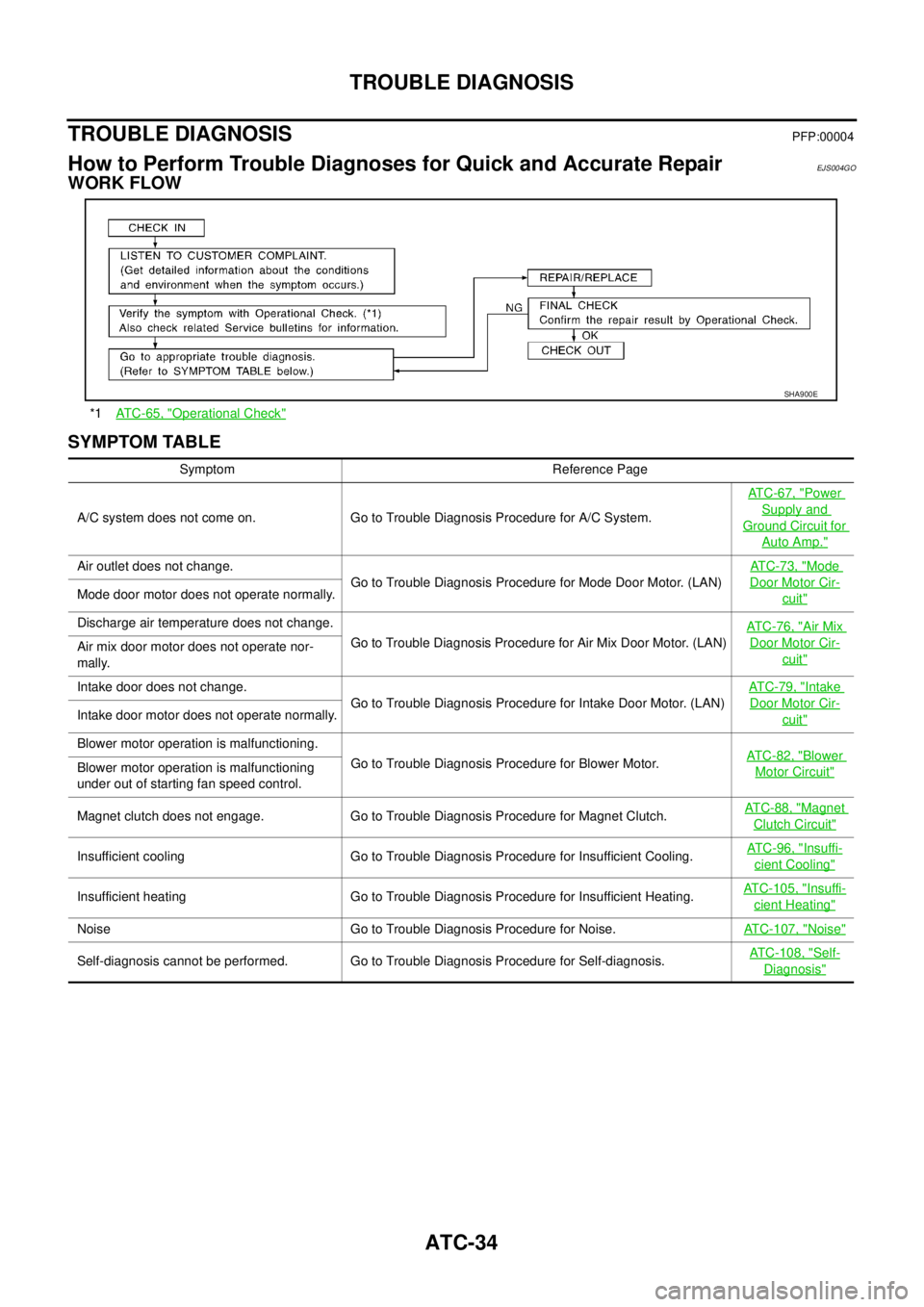
WORK FLOW
SYMPTOM TABLE
*1ATC-65, "Operational Check"
SHA900E
Symptom Reference Page
A/C system does not come on. Go to Trouble Diagnosis Procedure for A/C System.ATC-67, "
Power
Supply and
Ground Circuit for
Auto Amp."
Air outlet does not change.
Go to Trouble Diagnosis Procedure for Mode Door Motor. (LAN)ATC-73, "Mode
Door Motor Cir-
cuit"Mode door motor does not operate normally.
Discharge air temperature does not change.
Go to Trouble Diagnosis Procedure for Air Mix Door Motor. (LAN)AT C - 7 6 , "
Air Mix
Door Motor Cir-
cuit"Air mix door motor does not operate nor-
mally.
Intake door does not change.
Go to Trouble Diagnosis Procedure for Intake Door Motor. (LAN)AT C - 7 9 , "
Intake
Door Motor Cir-
cuit"Intake door motor does not operate normally.
Blower motor operation is malfunctioning.
Go to Trouble Diagnosis Procedure for Blower Motor.AT C - 8 2 , "
Blower
Motor Circuit"Blower motor operation is malfunctioning
under out of starting fan speed control.
Magnet clutch does not engage. Go to Trouble Diagnosis Procedure for Magnet Clutch.AT C - 8 8 , "
Magnet
Clutch Circuit"
Insufficient cooling Go to Trouble Diagnosis Procedure for Insufficient Cooling.ATC-96, "Insuffi-
cient Cooling"
Insufficient heating Go to Trouble Diagnosis Procedure for Insufficient Heating.ATC-105, "Insuffi-
cient Heating"
Noise Go to Trouble Diagnosis Procedure for Noise.ATC-107, "Noise"
Self-diagnosis cannot be performed. Go to Trouble Diagnosis Procedure for Self-diagnosis.ATC-108, "Self-
Diagnosis"
Page 3233 of 4555
TROUBLE DIAGNOSIS
ATC-55
C
D
E
F
G
H
I
K
L
MA
B
AT C
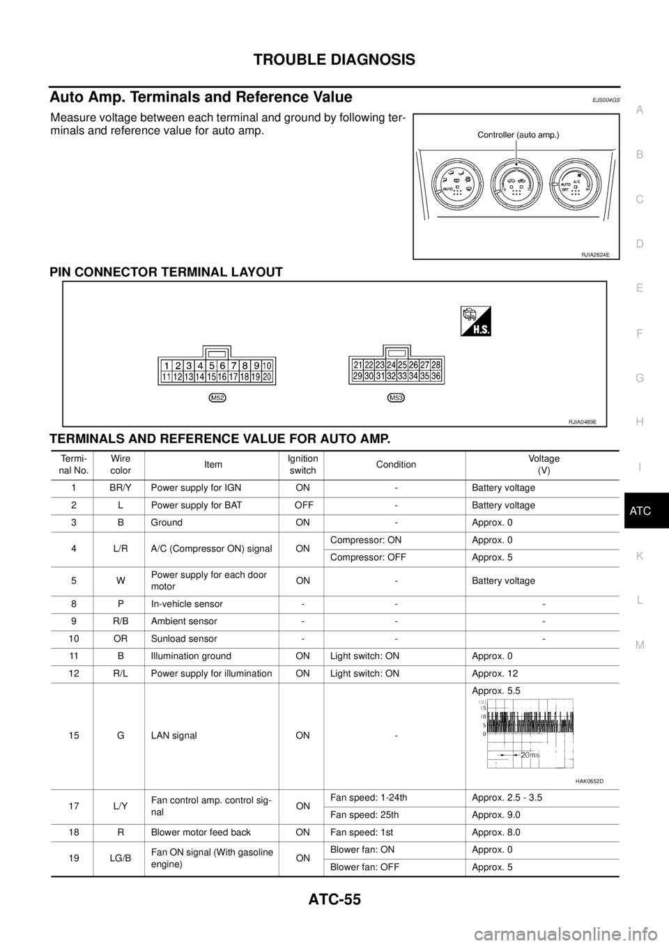
Auto Amp. Terminals and Reference ValueEJS004GS
Measure voltage between each terminal and ground by following ter-
minals and reference value for auto amp.
PIN CONNECTOR TERMINAL LAYOUT
TERMINALS AND REFERENCE VALUE FOR AUTO AMP.
RJIA2824E
RJIA0489E
Te r m i -
nal No.Wire
colorItemIgnition
switchConditionVoltage
(V)
1 BR/Y Power supply for IGN ON - Battery voltage
2 L Power supply for BAT OFF - Battery voltage
3 B Ground ON - Approx. 0
4 L/R A/C (Compressor ON) signal ONCompressor: ON Approx. 0
Compressor: OFF Approx. 5
5WPower supply for each door
motorON - Battery voltage
8 P In-vehicle sensor - - -
9 R/B Ambient sensor - - -
10 OR Sunload sensor - - -
11 B Illumination ground ON Light switch: ON Approx. 0
12 R/L Power supply for illumination ON Light switch: ON Approx. 12
15 G LAN signal ON -Approx. 5.5
17 L/YFan control amp. control sig-
nalONFan speed: 1-24th Approx. 2.5 - 3.5
Fan speed: 25th Approx. 9.0
18 R Blower motor feed back ON Fan speed: 1st Approx. 8.0
19 LG/BFan ON signal (With gasoline
engine)ONBlower fan: ON Approx. 0
Blower fan: OFF Approx. 5
HAK0652D
Page 3235 of 4555

TROUBLE DIAGNOSIS
ATC-57
C
D
E
F
G
H
I
K
L
MA
B
AT C
Self-diagnosis FunctionEJS004GT
DESCRIPTION
The self-diagnostic system diagnoses sensors, door motors, blower motor, etc. by system line.
Self-diagnosis is step-1 to 7. There are two ways of changing method during self-diagnosis.
�Switching to self-diagnosis step-1 to 4.
Shifting from usual control to the self-diagnostic system is accomplished by starting the engine (turning
the ignition switch from OFF to ON) and pressing A/C switch for at least 5 seconds. The A/C switch must
be pressed within 10 seconds after starting the engine (ignition switch is turned ON). This system will be
canceled by either pressing intake switch or turning the ignition switch OFF. Shifting from one step to
another is accomplished be means of turning fan control dial, as required.
�Switching to self-diagnosis step-5 to 7 (Auxiliary mechanism).
Shifting from usual control to the self-diagnostic system is accomplished by starting the engine (turning
the ignition switch from OFF to ON) and pressing intake switch for at least 5 seconds. The intake switch
must be pressed within 10 seconds after starting the engine (ignition switch is turned ON). This system
will be canceled by either pressing A/C switch or turning the ignition switch OFF. Shifting from one step to
another is accomplished by means of turning fan control dial, as required.
Page 3239 of 4555
TROUBLE DIAGNOSIS
ATC-61
C
D
E
F
G
H
I
K
L
MA
B
AT C
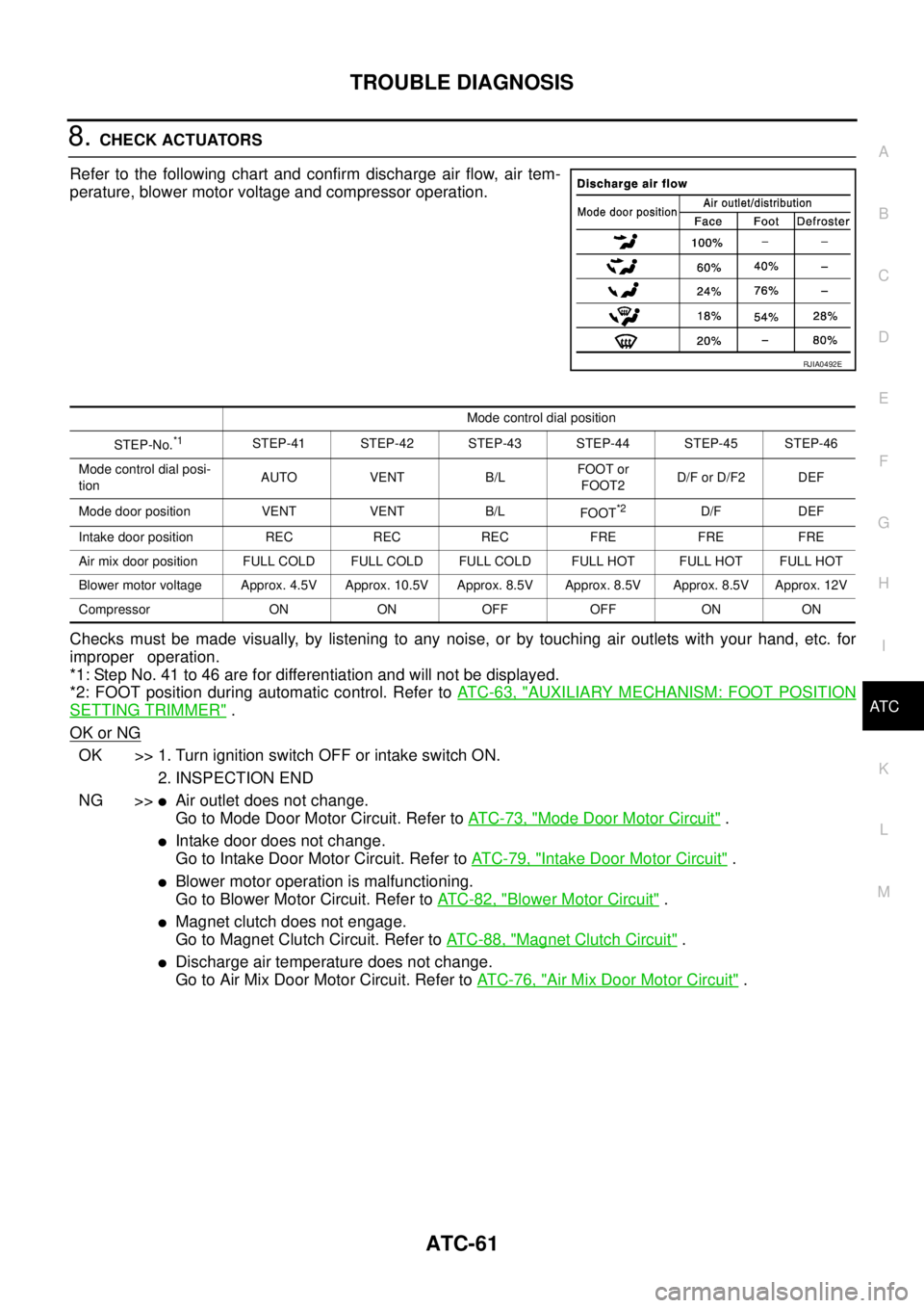
8. CHECK ACTUATORS
Refer to the following chart and confirm discharge air flow, air tem-
perature, blower motor voltage and compressor operation.
Checks must be made visually, by listening to any noise, or by touching air outlets with your hand, etc. for
improper operation.
*1: Step No. 41 to 46 are for differentiation and will not be displayed.
*2: FOOT position during automatic control. Refer to AT C - 6 3 , "
AUXILIARY MECHANISM: FOOT POSITION
SETTING TRIMMER" .
OK or NG
OK >> 1. Turn ignition switch OFF or intake switch ON.
2. INSPECTION END
NG >>
�Air outlet does not change.
Go to Mode Door Motor Circuit. Refer to AT C - 7 3 , "
Mode Door Motor Circuit" .
�Intake door does not change.
Go to Intake Door Motor Circuit. Refer to AT C - 7 9 , "
Intake Door Motor Circuit" .
�Blower motor operation is malfunctioning.
Go to Blower Motor Circuit. Refer to AT C - 8 2 , "
Blower Motor Circuit" .
�Magnet clutch does not engage.
Go to Magnet Clutch Circuit. Refer to AT C - 8 8 , "
Magnet Clutch Circuit" .
�Discharge air temperature does not change.
Go to Air Mix Door Motor Circuit. Refer to AT C - 7 6 , "
Air Mix Door Motor Circuit" .
RJIA0492E
Mode control dial position
STEP-No.
*1STEP-41 STEP-42 STEP-43 STEP-44 STEP-45 STEP-46
Mode control dial posi-
tionAUTO VENT B/LFOOT or
FOOT2D/F or D/F2 DEF
Mode door position VENT VENT B/L
FOOT
*2D/F DEF
Intake door position REC REC REC FRE FRE FRE
Air mix door position FULL COLD FULL COLD FULL COLD FULL HOT FULL HOT FULL HOT
Blower motor voltage Approx. 4.5V Approx. 10.5V Approx. 8.5V Approx. 8.5V Approx. 8.5V Approx. 12V
Compressor ON ON OFF OFF ON ON
Page 3243 of 4555
TROUBLE DIAGNOSIS
ATC-65
C
D
E
F
G
H
I
K
L
MA
B
AT C
Operational CheckEJS004GU
The purpose of the operational check is to confirm that the system operates properly.
CHECKING BLOWER
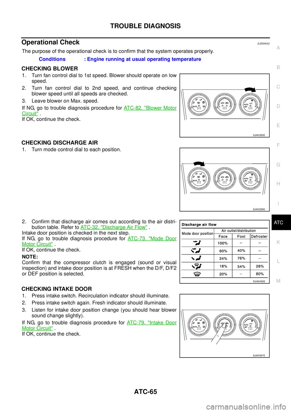
1. Turn fan control dial to 1st speed. Blower should operate on low
speed.
2. Turn fan control dial to 2nd speed, and continue checking
blower speed until all speeds are checked.
3. Leave blower on Max. speed.
If NG, go to trouble diagnosis procedure for AT C - 8 2 , "
Blower Motor
Circuit" .
If OK, continue the check.
CHECKING DISCHARGE AIR
1. Turn mode control dial to each position.
2. Confirm that discharge air comes out according to the air distri-
bution table. Refer to AT C - 3 2 , "
Discharge Air Flow" .
Intake door position is checked in the next step.
If NG, go to trouble diagnosis procedure for AT C - 7 3 , "
Mode Door
Motor Circuit" .
If OK, continue the check.
NOTE:
Confirm that the compressor clutch is engaged (sound or visual
inspection) and intake door position is at FRESH when the D/F, D/F2
or DEF position is selected.
CHECKING INTAKE DOOR
1. Press intake switch. Recirculation indicator should illuminate.
2. Press intake switch again. Fresh indicator should illuminate.
3. Listen for intake door position change (you should hear blower
sound change slightly).
If NG, go to trouble diagnosis procedure for AT C - 7 9 , "
Intake Door
Motor Circuit" .
If OK, continue the check.Conditions : Engine running at usual operating temperature
SJIA0395E
SJIA0396E
RJIA0492E
SJIA0397E
Page 3244 of 4555
ATC-66
TROUBLE DIAGNOSIS
CHECKING TEMPERATURE DECREASE
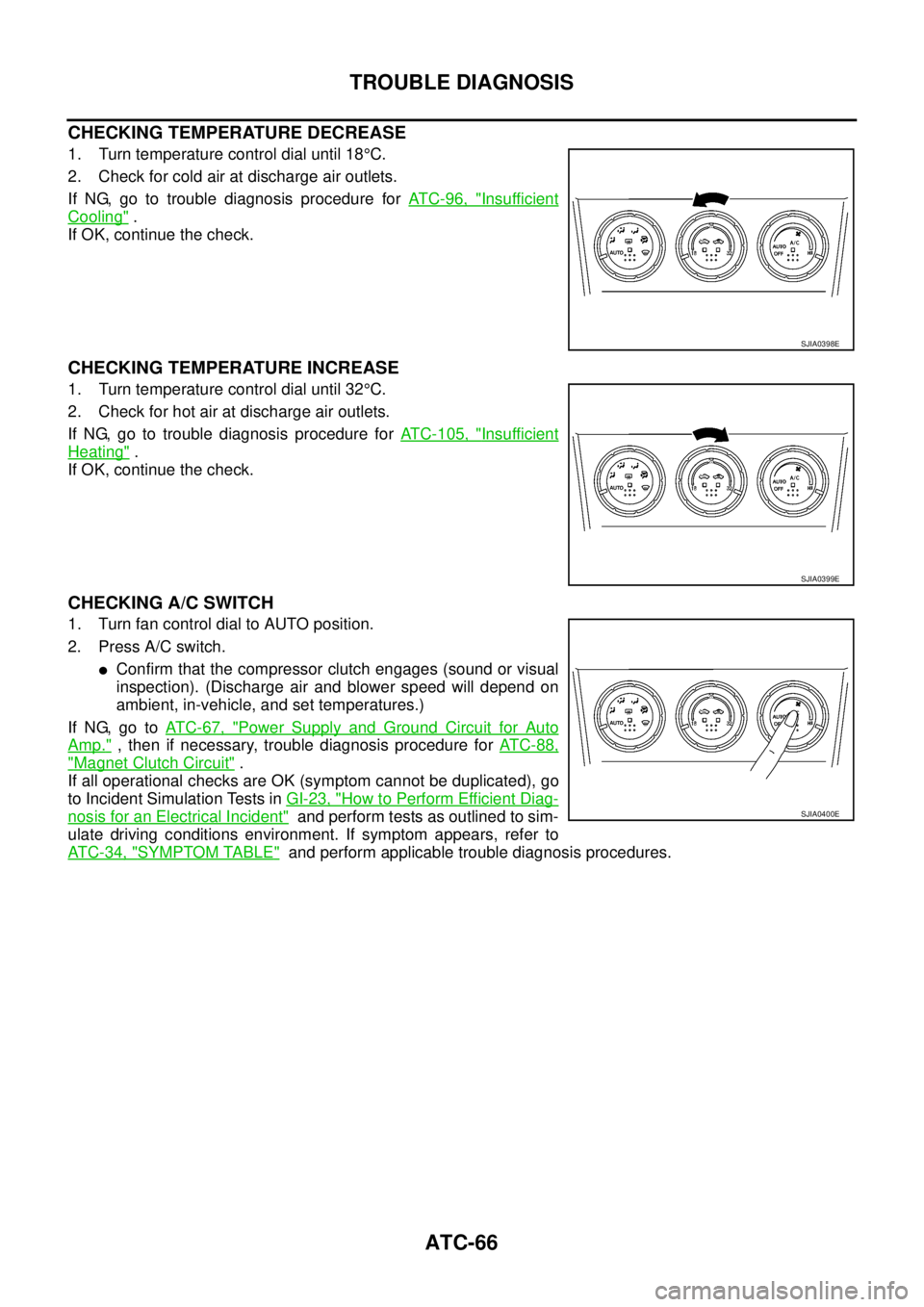
1. Turn temperature control dial until 18°C.
2. Check for cold air at discharge air outlets.
If NG, go to trouble diagnosis procedure for AT C - 9 6 , "
Insufficient
Cooling" .
If OK, continue the check.
CHECKING TEMPERATURE INCREASE
1. Turn temperature control dial until 32°C.
2. Check for hot air at discharge air outlets.
If NG, go to trouble diagnosis procedure for ATC-105, "
Insufficient
Heating" .
If OK, continue the check.
CHECKING A/C SWITCH
1. Turn fan control dial to AUTO position.
2. Press A/C switch.
�Confirm that the compressor clutch engages (sound or visual
inspection). (Discharge air and blower speed will depend on
ambient, in-vehicle, and set temperatures.)
If NG, go to AT C - 6 7 , "
Power Supply and Ground Circuit for Auto
Amp." , then if necessary, trouble diagnosis procedure for AT C - 8 8 ,
"Magnet Clutch Circuit" .
If all operational checks are OK (symptom cannot be duplicated), go
to Incident Simulation Tests in GI-23, "
How to Perform Efficient Diag-
nosis for an Electrical Incident" and perform tests as outlined to sim-
ulate driving conditions environment. If symptom appears, refer to
AT C - 3 4 , "
SYMPTOM TABLE" and perform applicable trouble diagnosis procedures.
SJIA0398E
SJIA0399E
SJIA0400E
Page 3245 of 4555
TROUBLE DIAGNOSIS
ATC-67
C
D
E
F
G
H
I
K
L
MA
B
AT C
Power Supply and Ground Circuit for Auto Amp.EJS004GV
SYMPTOM: A/C system does not come on.
INSPECTION FLOW
COMPONENT DESCRIPTION
Auto Amp. (Automatic Amplifier)
The auto amp. has a built-in microcomputer which processes infor-
mation sent from various sensors needed for air conditioner opera-
tion. The air mix door motor, mode door motor, intake door motor,
blower motor and compressor are then controlled.
The auto amp. is unitized with control mechanisms. Signals from
various switches and Potentio Temperature Control (PTC) are
directly entered into auto amp.
Self-diagnostic functions are also built into auto amp. to provide
quick check of malfunctions in the auto air conditioner system.
*1AT C - 6 5 , "Operational Check".*2ATC-68, "DIAGNOSTIC PROCE-
DURE FOR A/C SYSTEM".
RJIA2826E
RJIA2824E